
Related Manuals for Emerson TESCOM ERNG-X


Summary of Contents for Emerson TESCOM ERNG-X
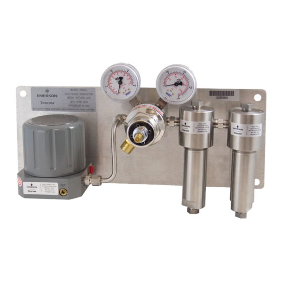
- Page 1 Instruction Manual dopsm2107x012 January 2017 ERNG-X TESCOM Product Manual Figure 1. ERNG-X...
-
Page 3: Table Of Contents
ERNG-X Table of Contents dopsm2107x012 January 2017 Contents Section 1: Introduction . . . . . . . . . . . . . . . . . . . . . . . . . . . . . . . . . . . . . . . . . . . . . . . . . . . . . 2 Section 2: Before You Begin . -
Page 4: Section 1: Introduction
Section 1: Introduction ERNG-X January 2017 dopsm2107x012 Section 1: Introduction This manual is valid only for ERNG-X . The instructions for individual components must also be read and followed . • ER5000 Getting Started (DOPSM2065XML2) • ER5000 Series User Manual (DOPSM2064X012) • Safety, Installation, Operations and Service Manual (DOPMS2080X012) Section 2: Before You Begin waRNING... -
Page 5: Safety, Installation And Operations Precautions
ERNG-X Section 2: Before You Begin dopsm2107x012 January 2017 Safety, Installation and Operations Precautions 2 .1 .1 TESCOM Electronic Controllers, Regulators and Filters waRNING Do not attempt to select, install, use or maintain this controller or accessory until you have read and fully understood these instructions and the individual component instructions. - Page 6 Section 2: Before You Begin ERNG-X January 2017 dopsm2107x012 9 . Clearly establish flow direction of the fluid before installation of controllers, regulators, valves and accessories . It is the responsibility of the user to install the equipment in the correct direction .
- Page 7 ERNG-X Section 2: Before You Begin dopsm2107x012 January 2017 waRNING Complete system integration and design is the responsibility of the user. The following are suggested malfunction design considerations but is not an all inclusive list. • Loss of ERNG-X controller power, loss of transducer power or loss of flow meter power • Interrupted or lost communication exchange to ERNG-X controller • Inlet solenoid malfunction leading to uncontrollable pressurization of spring case on pipeline pilot regulator...
-
Page 8: Section 3: Product Description
Section 3: Product Description ERNG-X January 2017 dopsm2107x012 CAUtioN Proper Component Selection 1 . Consider the total system design when selecting a component for use in a system . 2 . The user is responsible for assuring all safety and warning requirements of the application are met through his/her own analysis and testing . -
Page 9: Specifications
ERNG-X Section 3: Product Description dopsm2107x012 January 2017 ERNG-X aNaLOG SET-POINT SIGNaL (4-20 ma) REMOTE OPERaTIONS CONTROLLER (ROC) PIPELINE PILOT REGUlAtoR EXtERNAl PRESSURE oR FloW tRANSDUCER (4-20 ma) PiPEliNE mAiN REGUlAtoR Figure 2. Typical Installation Specifications Electrical Pressure Power Requirement : 20 .5 - 28 .5 VDC; ERNG-X Panel Supply Input: 340 mA Max ., 180 mA Nominal 2750 psig maximum... -
Page 10: Section 4: Installation
Section 4: Installation ERNG-X January 2017 dopsm2107x012 Section 4: Installation Installation Diagram Figure 3. wall Mount Panel Mounting 1 . Mount panel using the 4 mounting holes (A) . Note: Use 3/8" or 9 mm bolts . Connect Pressure Lines 1 . -
Page 11: Wiring
ERNG-X Section 4: Installation dopsm2107x012 January 2017 wiring 1 . Refer to ER5000 User Manual for wiring information . Communication The ER5000 communicates using a USB or RS485 interface . The required USB driver is provided on the ER5000 User Support Software and Manual CD or online . An RS485 communications link can be established between the ER5000 and a PC using either a USB to RS485 or RS232 to RS485 converter . -
Page 12: Special Control Features Available
Section 5: Maintenance ERNG-X January 2017 dopsm2107x012 Special Control Features available • Suspend Mode • Control Limits • Diaphragm Protection • Pulse Mode Note: Refer to ER5000 User Manual for more details . Section 5: Maintenance waRNING The maintenance and repair of pressure equipment must only be performed by trained personnel. -
Page 13: Section 6: Drawings
ERNG-X Section 6: Drawings dopsm2107x012 January 2017 Section 6: Drawings ERNG-X Dimensions 15.75 [400.0] 2X 1/4" – 18 NPT 4X Ø9.92 mm [127.0] [210.8] 14.75 [374.6] 2X 1/4" – 18 NPT FRONT VIEW 11.2 [283.3] [64.0] [123.4] [76.2] [26.1] [47.2] 1/2"... -
Page 14: C195-X Filter Assembly
© 2017 Emerson process management Regulator Technologies, Inc. All rights reserved. 01/17. Emerson Automation Solutions The Emerson logo is a trademark and service mark of Emerson Regulator Technologies Electric Co. All other marks are the property of their prospective owners.
Need help?
Do you have a question about the TESCOM ERNG-X and is the answer not in the manual?
Questions and answers