Table of Contents
Advertisement
FAILURE TO READ AND FOLLOW ALL INSTRUCTIONS CAREFULLY BEFORE
INSTALLING OR OPERATING THIS CONTROL COULD CAUSE PERSONAL
INJURY AND/OR PROPERTY DAMAGE.
The 50A65-5165 is an automatic gas interrupted
ignition control that employs a microprocessor to
continually monitor, analyze, and control the proper
operation of the gas burner, inducer, and fan.
Signals interpreted during continual surveillance of
the thermostat and flame sensing element initiate
automatic ignition of the burner, sensing of the flame,
and system shut-off during normal operation.
These controls incorporates system fault analysis for
quick gas flow shut-off, coupled with automatic ignition
retry upon sensing a fault correction. It is designed as a
replacement for the following controls:
Trane
CNT05164
CNT05165
Installation should be done by a qualified heating and
air conditioning contractor or licensed electrician.
If in doubt about whether your wiring is millivolt, line, or
low voltage, have it inspected by a qualified heating and
air conditioning contractor or licensed electrician.
Do not exceed the specification ratings.
All wiring must conform to local and national electrical
codes and ordinances.
This control is a precision instrument, and should
be handled carefully. Rough handling or distorting
components could cause the control to malfunction.
Following installation or replacement, follow
manufacturer's recommended installation/service
instructions to ensure proper operation.
CAUTION
!
Do not short out terminals on gas valve or primary
control. Short or incorrect wiring may damage
the thermostat.
White-Rodgers
50A65-475
50A65-476
50A65-5165
white-rodgers.com
emersonclimate.com
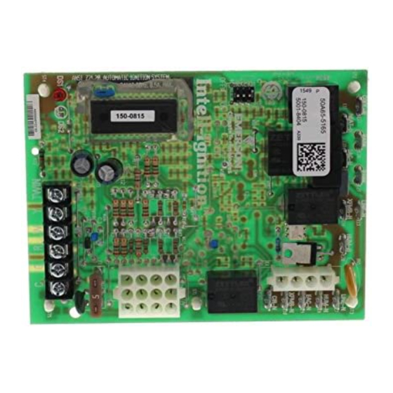
50A65-5165
Integrated Furnace Control
INSTALLATION INSTRUCTIONS
WARNING
!
Failure to comply with the following warnings could
result in personal injury or property damage.
FIRE HAZARD
• Do not exceed the specified voltage.
• Replace existing control with exact model and
dash number.
• Protect the control from direct contact with water
(dripping, spraying, rain, etc.).
• If the control has been in direct contact with
water, replace the control.
• Label all wires before disconnection when
servicing controls. Wiring errors can cause
improper and dangerous operation.
• Route and secure wiring away from flame.
SHOCK HAZARD
• Disconnect electric power before servicing.
• Ensure proper earth grounding of appliance.
• Ensure proper connection of line neutral and
line hot wires.
EXPLOSION HAZARD
• Shut off main gas to appliance until installation
is complete.
DESCRIPTION
PRECAUTIONS
PART NO. 37-7516B
Replaces 37-7516A
1515
Advertisement
Table of Contents

Related Manuals for Emerson White Rodgers 50A65-5165


Summary of Contents for Emerson White Rodgers 50A65-5165
- Page 1 50A65-5165 Integrated Furnace Control INSTALLATION INSTRUCTIONS FAILURE TO READ AND FOLLOW ALL INSTRUCTIONS CAREFULLY BEFORE INSTALLING OR OPERATING THIS CONTROL COULD CAUSE PERSONAL INJURY AND/OR PROPERTY DAMAGE. DESCRIPTION The 50A65-5165 is an automatic gas interrupted ignition control that employs a microprocessor to continually monitor, analyze, and control the proper operation of the gas burner, inducer, and fan.
-
Page 2: Specifications
SPECIFICATIONS ELECTRICAL RATINGS [@ 77°F (25°C)]: TIMING SPECIFICATIONS (All times are in seconds, unless noted otherwise Input Voltage: 25 VAC 50/60 Hz Max. Input Current @ 25 VAC: 0.45 amp 50A65-5165 Relay Load Ratings: Pre-Purge Valve Relay: 1.5 amp @ 25 VAC 50/60 Hz 0.6 pf Ignitor Warm-up Ignitor Current: 2.0 amp @ 80 VAC Trial for Ignition Period... - Page 3 WIRING TYPICAL SYSTEM WIRING DIAGRAM NEUTRAL (LINE) (LINE) 120 VAC 24 VAC CLASS II TRANSFORMER 24 VAC 50A65-5165 COOL HEAT CIRCU- LATOR PARK BLOWER PARK LINE XFMR INDUCER IGNITOR IND N HUMIDIFIER IGN N CIR N LINE N XFMR N HUM N ELECTRONIC EAC N...
-
Page 4: Terminal Type
WIRING TYPICAL SYSTEM WIRING TABLE TERMINAL SYSTEM COMPONENT 50A65-5165 TYPE CONNECTION TERMINAL low voltage thermostat W terminal (or equivalent) low voltage thermostat G terminal (or equivalent) Terminal low voltage thermostat R terminal (or equivalent) block with low voltage thermostat Y terminal (or equivalent) captive (2nd wire from Y terminal goes to 24 VAC HOT side of screws... -
Page 5: Option Switches
OPERATION OPTION SWITCHES specially designed to operate with the 50A65’s adaptive ignition routine to ensure the most efficient ignitor The option switches on the 50A65-5165 control are used temperature. to determine the length of the heat delay-to-fan-off periods At the end of the ignitor warm-up time, both valves in and cool delay-to-fan-off period. -
Page 6: Cool Mode
OPERATION COOL MODE SYSTEM LOCKOUT AND DIAGNOSTIC FEATURES In a typical system, a call for cool is initiated by closing the thermostat contacts. This energizes the 50A65 control and the compressor. The cool delay-to-fan-on period begins. SYSTEM LOCKOUT FEATURES After the delay period ends, the optional electronic air When system lockout occurs, the gas valve is de-energized, cleaner is energized, and the circulator fan is energized the circulator blower is energized at heat speed, and, if... - Page 7 OPERATION DEFINITION OF TERMS Inter-purge – The period of time intended to allow for the Auto Restart – After one (1) hour of internal or external lockout, the control will automatically reset itself and go dissipation of any unburned gas or residual products of into an auto restart purge for 60 seconds.
-
Page 8: Troubleshooting
Check ignitor or improper grounding Continuous Control failure Replace IFC Control failure Verify power to the control TECHNICAL SUPPORT: 1-888-725-9797 White-Rodgers is a business of Emerson Electric Co. The Emerson logo is a white-rodgers.com trademark and service mark emersonclimate.com of Emerson Electric Co.
Need help?
Do you have a question about the White Rodgers 50A65-5165 and is the answer not in the manual?
Questions and answers