
Related Manuals for Inepro IP Reader


Summary of Contents for Inepro IP Reader
- Page 1 Inepro IP Reader (Konica Minolta) Technical Manual | Inepro IP Reader (Konica Minolta) © 2019 Inepro B.V. All rights reserved...
- Page 2 We want to help you get the best result from your Inepro IP Reader (Konica Minolta). This manual contains information on how to do that; please read it carefully. Due to continuous product improvements this manual is subject to changes without notice.
- Page 3 Inepro IP Reader (Konica Minolta) All rights reserved. No parts of this work may be reproduced in any form or by any means - graphic, electronic, or mechanical, including photocopying, recording, taping, or information storage and retrieval systems - without the written permission of the publisher.
-
Page 4: Table Of Contents
Table of Contents Introduction Components Operating Procedures Communication Network Connections LEDs (Light Emitting Diodes) Relays Software configuration settings Inepro Business Server (Optional) Specifications Appendix I Notes... - Page 5 End of life dir ectives Inepro is pay ing a lot of attention to env ironmentally -friendly production. Your new dev ice contain materials w hich can be recy cled and reused. A t the end of its life specialised companies can dismantle the discarded dev ice to recy cle the reusable materials and to minimise the amount of materials to be disposed of.
-
Page 6: Introduction
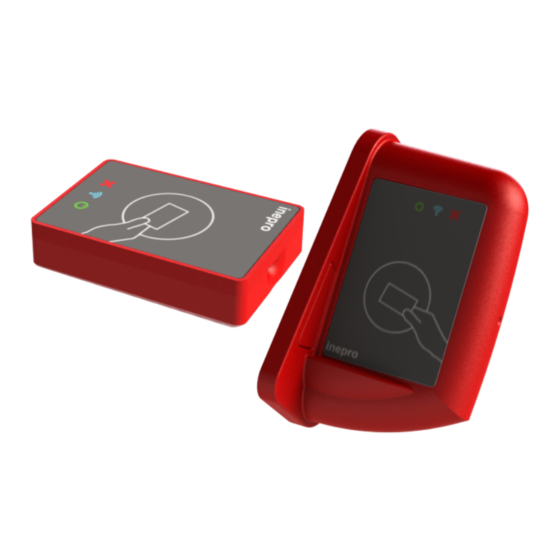
Introduction Part... - Page 7 Inepro IP Card Reader Multitag KoMi Function The purpose of the IP reader is to read the unique ID contained in the card that is presented to the reader and transfer this ID to a server. In most cases this data will be the card serial number. To facilitate this a variety of card reader software module have been developed.
-
Page 8: Components
Components Part... - Page 9 Components Components The IP Reader consists of the following components: · Grey Card Reader Housing - Grey Antenna Box - Antenna Box Cap 1 / Grey - Antenna Box Cap 2 / Grey · Controller Box · Wire Duct - Grey ·...
- Page 10 Some parts are already pre-assembled or have already be mounted. Like the Antenna board that is mounted in the pre- assembled Grey Card Reader housing (the grey antenna box). Inepro IP Reader (Konica Minolta)
-
Page 11: Operating Procedures
Operating Procedures Part... - Page 12 The IP controller board will then transfer this information to the server by means of an Ethernet connection. The server will receive the card’s data and returns an (error) code to the IP controller board. Inepro IP Reader (Konica Minolta)
-
Page 13: Communication
Communication Part... - Page 14 Alternative server It is possible to set up a second server for the IP reader. This allows the IP reader to look for an alternative server if the main server does not respond.
- Page 15 Communication IP Reader encryption protocol...
-
Page 16: Network Connections
Network Connections Part... - Page 17 Network Connections Network Connections Switch On the IP controller board there are two network connectors. The IP controller board can be used as a switch because of the Ethernet switch chip on board and can be placed between a wall outlet and an existing Ethernet device (like a printer or multifunctional device).
- Page 18 CARD led on = controller board detects card being presented to card reader. --> Green led on = Ethernet connection with internal switch chip --> Orange led blinking = data being transferred --> trough Ethernet connection Inepro IP Reader (Konica Minolta)
-
Page 19: Leds (Light Emitting Diodes)
LEDs (Light Emitting Diodes) Part... - Page 20 LEDs (Light Emitting Diodes) Inepro IP Reader (Konica Minolta)
- Page 21 LEDs (Light Emitting Diodes) Antenna Housing LED Inside the card reader’s housing a LED is mounted which can be used to let the user know that card data has been read and this data is presented to the server. The LED will also be used to show an error has occurred, by using different blink patterns.
- Page 22 The IP controller board will receive this data string and, after encryption, redirect this data to the server. This situation can cause the CARD LED and the RS232 LED to behave differently. Inepro IP Reader (Konica Minolta)
- Page 23 LEDs (Light Emitting Diodes) IP Controller Board Ethernet Connector LED's On each of the 2 Ethernet connectors on the IP controller board 2 LEDs are mounted with the same way of operating as a network switch/router. Status Display Connection Green exists (or orange Connection...
-
Page 24: Relays
Relays Part... - Page 25 Relays Relays Connection relais on IP reader board: Relay specifications Type: LUZ-5 (RAYEX ELEC) Maximum load AC: 2A 125Vac Maximum load DC: 2A 24Vdc Connection: Normally Open (contact pins are connected when the relay is activated) Connector specifications Type: B4B-XH-A JST-XH serie...
- Page 26 PCB trace specifications (at a current of 2A) Trace width: 1.5mm Copper thickness: 0.035 mm Temperature increase: 9 degrees centigrade Inepro IP Reader (Konica Minolta)
-
Page 27: Software Configuration Settings
Software configuration settings VIII Part... - Page 28 Software configuration settings The IP Reader Config Tool The configuration settings can be managed using the IP card reader config tool. When you start the configuration set-up program this screen will be displayed. Press the button to search for connected IP Readers.
- Page 29 Software configuration settings Please note that the IP address of the IP Reader has not been applied (0.0.0.0). Provided the DHCP server is up and running, the next screen will be displayed The DHCP server has found the IP Reader and has displayed the host name "PoE...
- Page 30 Name Description The name of this IP reader (like 'Printer Q745') This name will also be used as Name host name, it is sent to the DHCP serv er and DNS serv er if they are enabled. IP config Description...
- Page 31 Software configuration settings Reader config settings Description Setting 1 Setting 2 Setting 3 These settings will be addressed below. Data 1 Data 2 These fields will be used for retrieving the card reader data. The values entered here are dependent on the card that is used. Note: The raw data is supplied without conversion.
- Page 32 Wiegand protocol. If the value here is other Setting 3 then '0', then the IP reader will check if the code on the card is present. If the value is '0' the facility code is not checked.
- Page 33 Description Value Card Types Behaviour EM4x50, hitag1, hitag2, Q5 and Ti- RFID EM4x02, EM4x05, IP reader will read the EM4x50, hitag1, f ollowing protocols: hitag2 and Ti-RFID EM4x02, EM4x05, EM4x02, EM4x05, The card data of the EM4x50, hitag1, hitag2, EM4x50, hitag1, EM4x02 cards will be Q5 and Ti-RFID.
- Page 34 Data 2 Not applicable Note: When you can't find your card reader type in these tables, please contact Inepro for the settings for your reader. They will send you the latest version of this manual. Inepro IP Reader (Konica Minolta)
-
Page 35: Inepro Business Server (Optional)
Inepro Business Server (Optional) Part... - Page 36 Inepro Business Server The Inepro Business server is a module in the Inepro Back Office suite that is the central communication server for most of our software. All hardware and software is able to register and communicate via this server. If your system uses an Inepro Business...
- Page 37 4. Right-click on the group that you have just created and pick 'Create print release terminal'. The pop-up window below appears: 5. The name of this IP reader (like 'Printer Q745') This name will be shown in the Inepro Back Office Manager in the Terminal menu.
- Page 38 The pop-up window below appears: 7. Choose the setting 'IPReaderID'. 8. Retrieve the IP Reader serial (MAC address) from the IP Config Tool and insert it in the 'Value' field. 9. Click on OK and the reader is registered in the Inepro Back Office Suite.
- Page 39 Connect to the Inepro Back Office Manager 12. After the Business server has started again you should be able to find the reader that have been registered in the Inepro Back Office Manager in the 'Advanced' -> 'Terminals' menu : 13.
-
Page 40: Specifications
Specifications Part... - Page 41 Specifications Specifications Power Sw itch regulated, high efficiency Pow er Supply (via adapter) 12V DC adapter 1VA Pow er Supply (via PoE) Confirm IEEE 802.3 AF specifications Operation Voltage Range DC (via 10 to 20V DC adapter) Operation Voltage Range DC (via PoE) 40 to 60V DC At maximum (depending on Pow er Consum ption...
- Page 42 Appendix I Part...
- Page 43 Appendix I...
- Page 44 Notes Part...
- Page 45 Notes Notes This area is meant for the reader's notes:...
Need help?
Do you have a question about the IP Reader and is the answer not in the manual?
Questions and answers