
Related Manuals for Burkert 787 649


Summary of Contents for Burkert 787 649
- Page 1 Operating Instructions Bedienungsanleitung Instructions de Service Type 0911 2 stage controller 2-Punkt-Regler 2 Régulateur ponctuel Id. No. 787 649 787 658...
- Page 2 We reserve the right to make technical changes without notice. Technische Änderungen vorbehalten. Sous resérve de modification techniques. © 2004 - 2017 Bürkert Werke GmbH & Co. KG Operating Instructions 1706/02_EU-ML_00804544...
-
Page 3: Table Of Contents
2-STAGE CONTROLLER TYPE 0911 GENERAL INFORMATION ........................Symbols ................................. Safety notes ..............................Scope of delivery ............................Warranty provisions ..........................SYSTEM DESCRIPTION ..........................General description ..........................Operation ..............................Parameters ..............................Controlling the loads ..........................TECHNICAL DATA ............................ASSEMBLY, INSTALLATION AND COMMISSIONING ............ -
Page 4: General Information
GENERAL INFORMATION Symbols The following symbols are used in these operating instructions: marks a work step that must be carried out. ATTENTION! indicates information which, if ignored, could lead to a risk to your health or to the functionality of the device. NOTE indicates important additional information, tips and recommendations. -
Page 5: Scope Of Delivery
Scope of delivery Immediately after receiving the delivery, ensure that the contents agree with the scope of the delivery. This includes: • the Type 0911 controller • a set of operating instructions (where required, on a data carrier) • a front seal •... -
Page 6: System Description
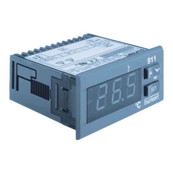
SYSTEM DESCRIPTION General description The Type 0911 front panel mounted device is an electronic temperature controller that is equipped with a PTC or NTC sensor input and a relay output for registering temperature. Operation down- wards wards LED1 Display SET button Fig. - Page 7 LED MESSAGES Mode Meaning Relay active Programming level (together with LED1) blinks Minimum switchover time Relay active LED1 blinks Programming level (together with VIEW THE SET VALUE Briefly press the SET button once. The set-value display appears in the display. Briefly press the SET button again, or wait 5 seconds in order to display the temperature.
-
Page 8: Parameters
HIGHEST STORED TEMPERATURE Briefly press the button once. The message Hi and and then the display of the maximum temperature appear. You can return to the normal display by pressing any button, or by waiting 5 seconds. RESET THE MAXIMUM AND MINIMUM TEMPERATURE You can acknowledge the stored value by holding the SET button down now for longer than 3 seconds, until the message rST appears on the display. - Page 9 Alarm delay 0 ... 255 min; Minimum time in which the at temperature conditions for an alarm situation Overshoot/Undershoot must be present. Low temperature alarm -50 °C / -58 °F Ald - Low temperature alarm after delay time ALd Over-temperature alarm 150 °C / 302 °F High temperature alarm after delay time ALd...
-
Page 10: Controlling The Loads
Controlling the loads CONTROLLER OUTPUT The regulation is dependent on the measured temperature (= sensor temperature). You can program the control direction (heating or cooling) with the parameter CH. CH = CL Cooling CH = HT Heating COOLING temperature SET+HY compressor Fig. -
Page 11: Technical Data
TECHNICAL DATA • Housing ABS, self-extinguishing • Dimensions Front 74 x 32 mm, Depth 60 mm • Assembly Panel-mounting unit for 29 x 71 mm cutout • Protection class IP65 from the front (only with front seal) IP20 from rear •... -
Page 12: Assembly, Installation And Commissioning
ASSEMBLY, INSTALLATION AND COMMISSIONING General information regarding the installation and operation ATTENTION! • Do not lay cables for inputs next to lines carrying voltage. • Avoid heavy vibrations, aggressive gases, heavy soiling and damp. NOTE • Before connecting the device, check that the power supply corresponds to the values shown on the rating plate. -
Page 13: Electrical Connections
Panel Mounting frame Front seal Fig. 4.2: Installation sequence Electrical connections Use cable with a cross-section of max. 2.5 mm Check the auxiliary power before connection the voltage supply (see Chapter Technical data ). Do not load the relay contacts higher than permitted. If necessary, use a contactor. -
Page 14: Factory Settings
PIN ASSIGNMENT 8(3) A / 250 V AC Room Operating N.C. Relay temperature voltage output Fig. 4.3: Pin assignment Factory setting Parameter Range Heating (°C) LS ... LU 0.1 ... 25.5 °C / 1 ... 255 °F -50 °C + SET / -58 °F + SET - 50 SET +150 °C / SET +302 °F -12 ... -
Page 15: Maintenance
MAINTENANCE When operated in accordance with the instruction in this handbook, the 0911 controller is maintenance-free. REPAIR WORK Faults ERROR MESSAGES Message Cause Effect Microprocessor fault Relay operation according to the Room sensor fault parameters Con and COF High temperature Outputs remain unchanged alarm Low temperature alarm... -
Page 16: Ordering Table For Basic Unit/Accessories
Ordering table for basic unit/accessories Article Order No. 2-stage controller 0911 24 V AC/DC 787 649 2-stage controller 0911 230 V AC 787 658 PTC sensor with 1.5 m cable, installation sleeve L = 62 mm 781 969 D = 6 mm... - Page 17 2-PUNKT-REGLER TYP 0911 ALLGEMEINE HINWEISE ........................Darstellungsmittel ........................... Sicherheitshinweise ..........................Lieferumfang ............................. Garantiebestimmungen ........................SYSTEMBESCHREIBUNG ........................Allgemeine Beschreibung ........................Bedienung ..............................Parameter ..............................Regelung der Lasten ..........................TECHNISCHE DATEN ..........................MONTAGE, INSTALLATION UND INBETRIEBNAHME ............ Allgemeine Hinweise zu Installation und Betrieb ..............
-
Page 18: Allgemeine Hinweise
ALLGEMEINE HINWEISE Darstellungsmittel In dieser Betriebsanleitung werden folgende Darstellungsmittel verwendet: markiert einen Arbeitsschritt, den Sie ausführen müssen. ACHTUNG! kennzeichnet Hinweise, bei deren Nichtbeachtung Ihre Ge- sundheit oder die Funktionsfähigkeit des Gerätes gefährdet ist. HINWEIS kennzeichnet wichtige Zusatzinformationen, Tipps und Empfehlungen. Sicherheitshinweise Bitte beachten Sie die Hinweise dieser Betriebsanleitung sowie die Einsatz- bedingungen und zulässigen Daten, die in dem Datenblatt des Reglers 0911... -
Page 19: Lieferumfang
Lieferumfang Überzeugen Sie sich unmittelbar nach Erhalt der Lieferung, ob der Inhalt mit dem angegebenen Lieferumfang übereinstimmt. Zu diesem gehören: • der Regler Typ 0911 • eine Betriebsanleitung (ggf. auf Datenträger) • eine Frontdichtung • zwei Befestigungsklammern Bei Unstimmigkeiten wenden Sie sich bitte umgehend an unser Kundencenter: Bürkert Steuer- und Regelungstechnik Service-Abteilung Chr.-Bürkert-Str. -
Page 20: Systembeschreibung
SYSTEMBESCHREIBUNG Allgemeine Beschreibung Das Fronttafel-Einbaugerät Typ 0911 ist ein elektronischer Temperaturregler, der zur Erfassung der Temperatur über einen PTC- bzw. NTC-Fühler-Eingang und einen Relais-Ausgang verfügt. Bedienung nach nach oben unten LED1 Display SET-Taste Bild 2.1: Frontansicht TASTEN Anzeige des Sollwertes, Ändern und Bestätigen einer Vorgabe während der Programmierphase Höchste gespeicherte Temperatur einsehen, Erhöhen von Werten während der Programmierphase... - Page 21 LED-MELDUNGEN Mode Bedeutung Relais aktiv Programmierebene (gemeinsam mit LED1) blinkt Mindestumschaltdauer Relais aktiv LED1 blinkt Programmierebene (gemeinsam mit SOLLWERT EINSEHEN Betätigen einmal kurz die SET-Taste. Die Sollwertan- zeige erscheint am Display. Betätigen Sie nochmals kurz die SET-Taste oder warten Sie 5 s, um die Temperatur anzeigen zu lassen.
-
Page 22: Parameter
HÖCHSTE GESPEICHERTE TEMPERATUR Betätigen Sie einmal kurz die Taste Die Meldung Hi und danach die Anzeige der maxi- malen Temperatur erscheinen. Zurück zur Normalanzeige gelangen Sie durch Betätigen einer beliebigen Taste oder Sie warten 5 s. RESET DER MAXIMALEN UND MINIMALEN TEMPERATUR Sie quittieren die gespeicherten Werte, indem Sie zunächst die SET-Taste länger als 3 s gedrückt halten, bis die Meldung rST am Display erscheint. - Page 23 Alarm-Verrögerung 0 ... 255 min; Mindestzeit, in der die Be- bei Temperatur dingungen für eine Alarm-Situation gege- Über-/Unterschreitung ben sein müssen. Alarm-Tieftemperatur - 50 °C / -58 °F Ald - Tieftemperatur-Alarm nach Verzögerungszeit ALd Alarm-Übertemperatur 150 °C / 302 °F Hochtemperatur-Alarm nach Verzögerungszeit ALd Konfiguration...
-
Page 24: Regelung Der Lasten
Regelung der Lasten REGLER-OUTPUT Die Regelung ist abhängig von der Mess-Temperatur (= Fühler-Temperatur). Den Wirksinn (Heizen oder Kühlen) programmieren Sie mit dem Parmeter CH. CH = CL Kühlen CH = HT Heizen KÜHLEN Bild 2.2: Kühlen Parameter CH = CL; Der Wert HY ist im Werk auf 2K voreingestellt. Überschreitet die Temperatur den Wert SET+HY, wird der Kompressor einge- schaltet und bei Unterschreitung von SET wieder abgeschaltet. -
Page 25: Technische Daten
TECHNISCHE DATEN • Gehäuse ABS, selbstverlöschend • Abmessungen Front 74 x 32 mm, Tiefe 60 mm • Montage Tafeleinbaugerät für Ausschnitt 29 x 71 mm • Schutzart IP65 von vorn (nur mit Frontdichtung) IP20 von hinten • Anschlüsse Schraubklemmen • Leitungsquerschnitt 2,5 mm •... -
Page 26: Montage, Installation Und Inbetriebnahme
MONTAGE, INSTALLATION UND INBETRIEBNAHME Allgemeine Hinweise zu Installation und Betrieb ACHTUNG! • Verlegen Sie die Kabel von Eingängen getrennt von spannungsführenden Leitungen. • Vermeiden Sie starke Vibration, aggressive Gase, starke Verschmutzung und Feuchtigkeit. HINWEIS • Prüfen Sie vor Anschluss des Gerätes, ob die Spannungs- versorgung den auf dem Typenschild angegebenen Werten entspricht. -
Page 27: Elektrische Anschlüsse
Panel Befestigungsrahmen Frontdichtung Bild 4.2: Einbau-Reihenfolge Elektrische Anschlüsse Verwenden Sie Kabel mit einem Querschnitt von maximal 2,5 mm Prüfen Sie die Hilfsenergie, bevor Sie die Spannungsversorgung anschließen (siehe Kapitel Technische Daten). Belasten Sie die Relais-Kontakte nicht mit höheren Leistungen, als zulässig. Schalten Sie gegebenenfalls Schütze nach. -
Page 28: Werkseinstellung
ANSCHLUSSBELEGUNG 8(3) A / 250 V AC Raum- Betriebs- N.C. Relais- temperatur spannung ausgang Bild 4.3: Anschlussbelegung Werkseinstellung Parameter Bereich Heizen (°C) LS ... LU 0,1 ... 25,5 °C / 1 ... 255 °F -50 °C + SET / -58 °F + SET - 50 SET +150 °C / SET +302 °F -12 ... -
Page 29: Wartung
WARTUNG Der Regler 0911 ist bei Betrieb entsprechend den in dieser Anleitung gegebe- nen Hinweisen wartungsfrei. INSTANDHALTUNG Störungen FEHLERMELDUNGEN Meldung Ursache Wirkung Mikroprozessor-Fehler Relais-Betrieb gemäß der Fehler Raum-Fühler Parameter Con und COF Hochtemperatur-Alarm Ausgänge bleiben unberührt Tieftemperatur-Alarm Ausgänge bleiben unberührt FEHLER QUITTIEREN ÜBER DIE TASTATUR Meldung EE - Mikroprozessor-Fehler Betätigen Sie eine beliebige Taste. -
Page 30: Bestelltabelle Grundgerät/Zubehör
Bestelltabelle Grundgerät/Zubehör Artikel Best.-Nr 2-Punkt-Regler 0911 24 V AC/DC 787 649 2-Punkt-Regler 0911 230 V AC 787 658 PTC-Fühler mit 1,5 m Kabel, Einbauhülse L = 62 mm 781 969 D = 6 mm Schutzabdeckung 787 937 Trafo 230 V / 24 V 3 VA... - Page 31 2 RÉGULATEUR PONCTUEL TYPE 0911 REMARQUES GÉNÉRALES ......................Symboles de reprèsentation ......................Consignes de sécurité ........................Fourniture ..............................Clauses de garantie ..........................DESCRIPTION DU SYSTÈME ......................Description générale ..........................Commande ..............................Paramètres ..............................Régulation des charges ........................CARACTÉRISTIQUES TECHNIQUES ..................MONTAGE, INSTALLATION ET MISE EN SERVICE ............
-
Page 32: Remarques Générales
REMARQUES GÉNÉRALES Symboles de représentation Les symboles de représentation suivants sont utilisés dans ces instructions de service: marque une étape de travail à exécuter. ATTENTION! marque des instructions dont l’inobservation risque de porter atteinte à votre santé et à la fonctionnalité de l’appareil. REMARQUE marque des informations importantes additionnelles, des conseils et des recommandations. -
Page 33: Fourniture
Fourniture S’assurer immédiatement après réception de la fourniture si le contenu est conforme à ce qui a été indiqué. Font partie de celle-ci: • le régulateur type 0911 • des instructions de service (évent. sur support de données) • un joint frontal •... -
Page 34: Description Du Système
DESCRIPTION DU SYSTÈME Description générale L’appareil rapporté sur le tableau frontal, type 0911 est un thermorégulateur électronique qui dispose d’une entrée pour capteur NTC ou PTC et d’une sortie de relais pour saisir la température. Maniement vers vers LED1 Afficheur le bas le haut Touche SET... - Page 35 MESSAGES LED Mode Signification allumée Relais actif Niveau de programmation (ensemble avec LED1) clignote Durée minimale de commutation, Relais actif LED1 clignote Niveau de programmation (ensemble avec CONSULTER VALEUR DE CONSIGNE Presser une fois brièvement la touche SET. La valeur de consigne apparaît sur l’afficheur. Presser encore une fois brièvement la touche SET ou attendre 5 s pour faire afficher la température.
-
Page 36: Paramètres
TEMPÉRATURE LA PLUS HAUTE EN MÉMOIRE Presser une fois brièvement la touche Le message Hi et ensuite l’affichage de latempérature maximale apparaissent. Vous revenez à l’affichage normal en pressant une touche quelconque ou bien vous attendez 5 s. RESET DE LA TEMPÉRATURE MAXIMALE ET DE LA TEMPÉRATURE MINIMALE Vous accusez réception des valeurs en mémoire en pressant d’abord la touche SET plus de 3 s jusqu’à... - Page 37 *ALd Temporisation d’alarme 0 ... 255 min; temps minimal dans en cas de non atteinte lequel les conditions doivent être ou de dépassement de la données pour une situation d’alarme. température Basse température -50 °C / -58 °F d’alarme Ald - basse température d’alarme après temporisation ALd Haute température 150 °C / 302 °F...
-
Page 38: Régulation Des Charges
Régulation des charges SORTIE DU RÉGULATEUR La régulation dépend de la température de mesure (= température du capteur). Vous programmez le sens d’action (chauffer ou refroidir) avec le paramètre CH = CL Refroidir CH = HT Chauffer REFROIDIR température SET+HY compresseur Figure 2.2: Refroidir Paramètre CH = CL;... -
Page 39: Caractéristiques Techniques
CARACTÉRISTIQUES TECHNIQUES • Boîtier ABS, autoextincteur • Dimensions Devant 74 x 32 mm, profondeur 60 mm • Montage Appareil de tableau rapporté pour coupe 29 x 71 mm • Protection IP65 de devant (seulement avec joint frontal) IP20 de derrière •... -
Page 40: Montage, Installation Et Mise En Service
MONTAGE, INSTALLATION ET MISE EN SERVICE Remarques générales sur l’installation et le service ATTENTION! • Poser les câbles séparés des entrées et de lignes conductrices de tension. • Eviter les fortes vibrations, les gaz agressifs, le fort encrassement et l’humidité. REMARQUE •... -
Page 41: Branchements Électriques
Panneau Cadre de fixation Joint frontal Figure 4.2: Ordre de montage Branchements électriques Utiliser des câbles ayant une section de 2,5 mm² au maximum. Contrôler l’énergie auxiliaire avant de brancher la tension d’alimentation (voir chapitre Caractéristiques techniques). Ne pas charger les contacts de relais avec des puissances plus élevées qu’admises. -
Page 42: Réglage Usine
AFFECTATION DES BROCHES 8(3) A / 250 V Température Tension de N.C. Sortie ambiante service de relais Figure 4.3: Affectation des broches Réglage usine Paramètre Domaine Chauffage (°C) LS ... LU 0,1 ... 25,5 °C / 1 ... 255 °F -50 °C + SET / -58 °F + SET - 50 SET +150 °C / SET +302 °F... -
Page 43: Entretien
ENTRETIEN Le régulateur 0911 est exempt d’entretien s’il est mis en service conformément aux indications données dans ces instructions. MAINTENANCE Pannes MESSAGES D’ERREUR Messages Cause Action Erreur du microprocesseur Erreur du capteur Fonctionnement du relais selon d'espace les paramètres Con et COF Alarme température Sorties restent intouchées élevée... - Page 44 Table de commande appareil de base/accessoires Article N° cde Régulateur à 2 positions 0911 24 V AC/DC 787 649 Régulateur à 2 positions 0911 230 V AC 787 658 Capteur PTC avec câble de 1,5 m, gaine de montage 781 969...
- Page 45 Fax + 49 (0) 7940 - 10 91 448 E-mail: info@de.buerkert.com International Contact addresses can be found on the internet at: Die Kontaktadressen finden Sie im Internet unter: Les adresses se trouvent sur internet sous : www.burkert.com Bürkert Company Locations...
- Page 46 The smart choice of Fluid Control Systems www.buerkert.com...
Need help?
Do you have a question about the 787 649 and is the answer not in the manual?
Questions and answers