
Subscribe to Our Youtube Channel
Related Manuals for ELAUT Benchmark Games Fireball


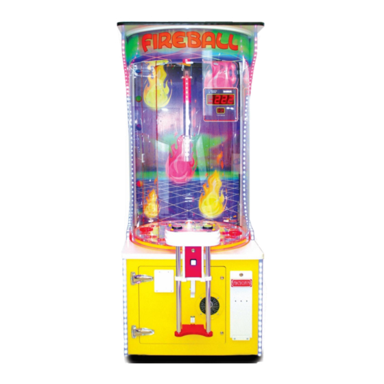
Summary of Contents for ELAUT Benchmark Games Fireball
- Page 1 888-583-1000 TEL: (561)588-5200 Fax: (561)493-2999 Customer Service: (561)253-3311 www.benchmarkgames.com 51 Hypoluxo Road Hypoluxo, FL 33462 166MAN001...
-
Page 2: Table Of Contents
Table of Contents Manual Revision History ................................ 2 Basic Components .................................. 3 Game Setup .................................... 4 Game Play Sequence/Behavior ............................4 Payouts and adjustments ..............................5 Programming Option ................................6 Programing Menu Tree ............................... 6 Technical Operation ................................7 Ball Drop Operation ................................7 Wheel Location and Ball Scoring ............................ -
Page 3: Manual Revision History
Manual Revision History Revision A – Released to production 01/29/18 Revision B – Updated Programing chart 06/11/18 Revision C – Updated Wheel Options 07/23/18 Revision D – Updated Part Numbers and images 04/29/19... -
Page 4: Basic Components
Basic Components:... -
Page 5: Game Setup
Game Setup: Unloading/Assembly: Carefully remove packing material and unload machine from pallet Locate power cord shipped in bag in the cash box. Connect cord to power input on the game. Plug cord into the wall. Toggle power switch to power game on. - Run through the ‘Programming Mode’... -
Page 6: Payouts And Adjustments
Payout and Adjustment *Note: Standard machine assumes 1 cent ticket value. Custom wheel values may be necessary if running anything different. We recommend running the machine at the default factory settings as a starting point. Table 1 (Dollar Wheel) Table 2 (25 Cent - Standard) Table 3 (50 Cent) Table 4... -
Page 7: Programming Option
Table 5 (25 cent 2 point) Programing Options: To Enter Programming mode, you will need to locate the Power Distribution Board (see Main Electronic Components). There are 3 buttons labeled “Back”, “Program”, and “Next”. 1. Press the middle button or “Program” once to enter Program mode. - Page 8 1 Clear Credits? 2 Clear Tickers? 1 Game Volume Range 0 to 255 3 Game Sounds 2 Attraction Volume Range 0 to 255 3 Bonus Round Range 0 to 255 Volume 1 Pulse Per Credits Range 1 to 8 2 Play per credit Range 1 to 8 3 Two Cents Tickets Yes / No...
-
Page 9: Technical Operation
Technical Operation: Ball Drop Operation When the ball is lifted to the Ball Drop Assembly it will roll down until it hits the ball alert switch indicating that a ball is ready to be played. Once a credit is inserted and the Drop Ball Button has been pressed, the Solenoid is activated pulling the plunger up and away from the ball allowing it to roll down the Ball Chute and on the... -
Page 10: Main Electronic Components
Main Electronic Components Circuit Board Location Power Distribution Board Quad Stepper Board Main Board Meters Located in the lower cabinet on the left-hand side. - Page 11 Main CPU Board Part Number: 166PCB001 Location: In lower cabinet on the left. ID Switch Setting: 0100(Off, On, Off, Off) This board is the main controller of the game. It decides all the game actions and commands the other boards to act according to the game scheme. Quad Stepper Controller Board Part Number: PCB00068 Location: In lower cabinet on the left.
- Page 12 Power Distribution Board Part Number: PCB00032 Location: In lower cabinet on the left. ID Switch Setting: None This board sends power to the main board, light board, quad board, and lights. Coins in/ Tickets out Meter Part Number:500ASM024 Location: In lower cabinet on the floor on the game. These meters measure the Coins entered the machine and how many Tickets have been paid out.
- Page 13 Bonus 4 Digit Display Part Number: PCB00120 Location: On the back wall on the top right. Above the credit display. ID Switch Setting: 0000(All Off) This display shows the value of the bonus to be won when ball lands on the Fireball Bonus hole. Credit/Ball Count 2 Digit Display Part Number: PCB00003 Location: On the back wall on the top right.
- Page 14 Scoring Opto Receiver Part Number: PCB00025 Location: Under the playfield wheel toward the back of the game. ID Switch Setting: N/A These receiver boards look for the opposite transmitter and send a signal to score the ball as it passes through. Scoring Opto Transmitter Part Number: PCB00029 Location: Under the playfield wheel toward the back of the game.
-
Page 15: Error Codes And Trouble Shooting Guide
Error Code and Troubleshooting Guide When the game registers an error, the game will start a self-diagnosis to clear any errors found. If the Error could not be self-resolved please review trouble shooting guides below. E-1: General RS485 Communication Error This error occurs when the 485-communication chain has been disrupted. - Page 16 E-3: Game is Out of Tickets This error occurs when Ticket Disperser does not sense the tickets. Troubleshooting: Check ticket bins have tickets and are loaded onto the ticket dispenser. For Triple Ticket Dispenser trouble shooting please see page (Enter Page number) E-4/E-11/E-13: Quad Stepper Communication Error/Wheel Stepper Communication error This error occurs when the Quad stepper controller board is not communication with the Main board.
- Page 17 Check continuity on the Blue and Gray wires. Ω 1. Set their volt meter to Ohms Ω 2. Place prongs on both end one gray wire. You should have 0 Ohms 3. Repeat step 2 for blue wire. Check continuity between the blue and gray wires. Ω...
- Page 18 E-7: LED RGB Communication Error. This error occurs when the LED RGB light board not communicating with the Main board. Troubleshooting: Check the plug going into the LED RGB Light Board. 1. Check that there are no cold solder joints. 2.
- Page 19 E-9: EEPROM R/W Failure Troubleshooting: Check Power is going to board 1. On the Main board there are 2 lights. a. The 3.3V light. Should be on solid. b. The CPU light. Should be blinking. 2. On the J1 Connector check your voltage. a.
- Page 20 E-14 - E-16: Main Board Software Errors This error occurs when internal checks in board report fault. Troubleshooting: Check Power is going to board 1. On the Main board there are 2 lights. a. The 3.3V light. Should be on solid. b.
-
Page 21: Board Pin Out Sheets
Board Pin Out Sheets Main Board: Connector Pin # Type Definition OUTPUT Ticket Enable OUTPUT Ticket Run OUTPUT Ball Drop Solenoid OUTPUT Inside cabinet Lights OUTPUT Black Lights OUTPUT Playfield Lights OUTPUT Marquee OUTPUT Ball Drop Solenoid Bottom OUTPUT Hard Meter (Tickets) Not used OUTPUT Hard Meter (Credit) - Page 22 INPUTS Internal row, Wheel Score Sensor INPUTS Player Sw.2/Menu Down sw. INPUTS Menu / Enter switch GROUND 12V Negative GROUND 12V Negative 12V+ 12V Positive 12V+ 12V Positive Speaker - Speaker Negative GROUND Ground Speaker + Speaker Positive RS485 A Serial COM Port RS485 B Serial COM Port...
- Page 23 Quad Stepper Controller Board: Connector Pin # Type Definition M1-A Wheel (blue) M1-A Wheel (green) M2-A M2-A M3-A Ball Lift (blue) M3-A Ball Lift (green) M4-A M4-A M1-B Wheel (pink) M1-B Wheel (black) M2-B M2-B M3-B Ball Lift (pink) M3-B Ball Lift (black) M4-B M4-B...
-
Page 24: Game Components
Game Components: Balls Part Number: 115BLL001 Description: This game requires 7 balls at any given time. Note: We recommend changing the balls every 6-9 months, depending on game usage. Drive Belt Part Number: BLT10011 Description: Small Belt located in the back of the cabinet. Attaches the Ball Lift motor to the pulley system. - Page 25 Blue Roller for Motor Part Number: GEN00169 Description: Rubber roller that sits on the playfield motor and spins the large playfield wheel. Roller Bearing Assembly for Wheel Part Number: 115ASM016 Description: Roller bearing assembly that the playfield wheel rides on. Playfield Motor Assembly Part Number: 500ASM127 Description: This motor spins the playfield wheel for game play.
Need help?
Do you have a question about the Benchmark Games Fireball and is the answer not in the manual?
Questions and answers