
Related Manuals for Zeiss OPMI VARIO


Summary of Contents for Zeiss OPMI VARIO
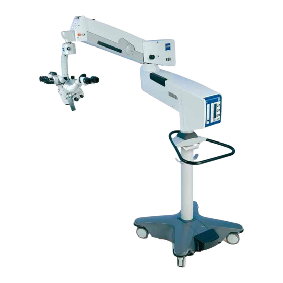
- Page 1 OPMI VARIO ® on S8, S81 & S88 Suspension Systems Instructions for use G-30-1607-en Issue 5.0 Printed on 30. 01. 2009...
-
Page 2: Key To Symbols
The hand provides hints on the use of the instrument or other tips for the user. ® OPMI is a registered trademark of Carl Zeiss Surgical GmbH G-30-1607-en OPMI® VARIO on S8, S81 & S88 Suspension Systems Issue 5.0 Printed on 30. 01. 2009... -
Page 3: Table Of Contents
Contents – Key to symbols Functions at a glance – OPMI® VARIO – S88 floor stand – S88 floor stand with lifting column – S8 ceiling mount – S81 ceiling mount Safety – Notes on installation and use – Safety devices of the suspension systems –... - Page 4 – Instrument tray (option) – Video monitor (option) S88 floor stand with lifting column – Intended use – Description of the modules – Design – Stand base with lifting column – Connector panel S8 ceiling mount – Intended use – Description of the modules –...
- Page 5 Operation Checklist Positioning the S88 floor stand Using the display and key field – General functions – OPMI Vario on the suspension system, user interface with SpeedFokus option Procedure G-30-1607-en OPMI® VARIO on S8, S81 & S88 Suspension Systems Issue 5.0...
- Page 6 – Spare parts – Accessories – Disposal Technical data – Technical data of OPMI VARIO – Technical data of S88 floor stand – Technical data of S88 floor stand with lifting column – Technical data of S8 ceiling mount – Technical data of S81 ceiling mount –...
-
Page 7: Functions At A Glance
Functions at a glance Functions at a glance OPMI® VARIO S88 floor stand S88 floor stand with lifting column S8 ceiling mount S81 ceiling mount G-30-1607-en OPMI® VARIO on S8, S81 & S88 Suspension Systems Issue 5.0 Printed on 30. 01. 2009... -
Page 8: Opmi Vario
Functions at a glance ® OPMI VARIO Adjusting the eyecup and the prescription page 64 Adjusting the interpupillary distance page 62 Adjusting the friction of vertical adjustment page 54 Recentering the X-Y coupling page 60 Adjusting the friction of the OPMI® axis of rotation page 60 Manual zoom setting page 56... - Page 9 Functions at a glance 11 12 15 16 17 G-30-1607-en OPMI® VARIO on S8, S81 & S88 Suspension Systems Issue 5.0 Printed on 30. 01. 2009...
-
Page 10: S88 Floor Stand
Functions at a glance S88 floor stand Control panel page 70 Illumination system page 66 Releasing the magnetic brakes of the suspension page 72 system Limiting the suspension arm's downward movement page 72 Removing/mounting the coupling for the page 72 surgical microscope Balance setting page 72... - Page 11 Functions at a glance 8 9 10, 11, 12 G-30-1607-en OPMI® VARIO on S8, S81 & S88 Suspension Systems Issue 5.0 Printed on 30. 01. 2009...
-
Page 12: S88 Floor Stand With Lifting Column
Functions at a glance S88 floor stand with lifting column Xenon illumination system Selecting a filter page 68 Manual activation of backup bulb page 66 Resetting the counter page 68 Opening the lamp module page 68 Red segment is lit - backup bulb is in use page 66 Control panel Lamp housing of xenon illumination system... - Page 13 Functions at a glance 14 15 16, 17, 18 G-30-1607-en OPMI® VARIO on S8, S81 & S88 Suspension Systems Issue 5.0 Printed on 30. 01. 2009...
-
Page 14: S8 Ceiling Mount
Functions at a glance S8 ceiling mount Locking the suspension arm in its horizontal position page 72 Releasing the magnetic brakes of the suspension system page 72 Balance setting page 72 Illumination system page 66 Control panel (rotatable through 180° or 70°) page 70 Connecting the foot control panel or hand switch, page 106... - Page 15 Functions at a glance G-30-1607-en OPMI® VARIO on S8, S81 & S88 Suspension Systems Issue 5.0 Printed on 30. 01. 2009...
-
Page 16: S81 Ceiling Mount
Functions at a glance S81 ceiling mount Locking the suspension arm in its horizontal position page 72 Releasing the magnetic brakes of the suspension system page 72 Balance setting page 72 Illumination system page 66 Control panel (rotatable through 180° or 70°) page 70 Option: hand control panel socket for ceiling track mount page 112 Plugging in the remote control connector... - Page 17 Functions at a glance G-30-1607-en OPMI® VARIO on S8, S81 & S88 Suspension Systems Issue 5.0 Printed on 30. 01. 2009...
- Page 18 Functions at a glance G-30-1607-en OPMI® VARIO on S8, S81 & S88 Suspension Systems Issue 5.0 Printed on 30. 01. 2009...
-
Page 19: Safety
Safety Safety Notes on installation and use Safety devices of the suspension systems Warning labels and notes G-30-1607-en OPMI® VARIO on S8, S81 & S88 Suspension Systems Issue 5.0 Printed on 30. 01. 2009... - Page 20 Safety The device described in this manual has been designed and tested in ac- cordance with Carl Zeiss safety standards as well as German and inter- national standards. This guarantees a high degree of instrument safety. The system described in this user manual has been designed in compli- ance with the requirements of: –...
-
Page 21: Notes On Installation And Use
• Over longer distances (e.g. removal, return for repair, etc), the instru- ment may only be transported in the original packaging or in special return packaging. Please contact your dealer or the Carl Zeiss service team. • Use this instrument only for the applications described. - Page 22 Safety • Only use the instrument with the accessories supplied. Should you wish to use other accessory equipment, make sure that Carl Zeiss or the equipment manufacturer has certified that its use will not impair the safety of instrument. •...
- Page 23 Safety Connection of a laser micromanipulator The link-up of a laser micromanipulator with the OPMI results in a medical system for which the system manufacturer must meet the necessary re- quirements (approval, qualification, laser protection, etc.). Please note the user manuals provided by the laser micromanipulator manufacturer and laser manufacturer.
- Page 24 – Ensuring that the navigation system is only connected by person- nel who have undergone appropriate training and instruction. – Contacting the local Carl Zeiss representative for any inquiries that may arise. – Implementation of a procedure that guarantees the calibration of the surgical microscope which is absolutely vital for the use of the Carl Zeiss components "Surgical microscope on suspension sys-...
- Page 25 • The antenna manufacturer must confirm that his antenna has been tested and certified for operation with the respective Carl Zeiss surgi- cal microscope on a suspension system in accordance with the re- quirements specified in the Carl Zeiss interface description "Navigation Interface for Carl Zeiss Surgical Microscopes".
- Page 26 Safety Requirements for operation • For ceiling mounts only: Our service staff or a qualified person ap- pointed by us will install the system on ceiling anchors which have been properly mounted by the construction engineers responsible. These ceiling anchors must comply with the specifications contained in our planning manual.
- Page 27 Safety • Make sure that the instrument has been switched off before you change the xenon lamp module. When switched on, the ignition sys- tem generates high voltage. • The xenon illumination system is a high-intensity light source which - if used improperly - can cause thermal injury to skin or tissue.
-
Page 28: Safety Devices Of The Suspension Systems
Safety Safety devices of the suspension systems 1 Release bar Allows non-sterile persons to release the magnetic brakes of the sus- pension system. 2 Adjustment screw for limiting the downward travel Use this screw to set the minimum vertical distance (working distance) from the surgical field. - Page 29 Safety G-30-1607-en OPMI® VARIO on S8, S81 & S88 Suspension Systems Issue 5.0 Printed on 30. 01. 2009...
- Page 30 Safety Stand lifting column 1 Key to set the optimum viewing height of the surgical microscope or for downward movement into the transport position. As long as you keep switch (1) pressed down, the lifting column (2) in the stand base moves upwards or downwards, depending on the po- sition of the switch.
- Page 31 Safety G-30-1607-en OPMI® VARIO on S8, S81 & S88 Suspension Systems Issue 5.0 Printed on 30. 01. 2009...
- Page 32 Safety Xenon illumination system Warning! The xenon lamp has a limited service life of 500 h. If used beyond its maximum service life, the xenon lamp may explode. • Replace the xenon lamp in good time. • Reset the service hour counter to "0" after replacing the lamp. Warning! Lamp rupture (audible as a loud bang) may lead to jamming of the lamp module and/or failure of the electronics modules.
- Page 33 Safety G-30-1607-en OPMI® VARIO on S8, S81 & S88 Suspension Systems Issue 5.0 Printed on 30. 01. 2009...
- Page 34 Safety • Pull out the lamp module as far as it will go. • Turn knob (1) through 180° until it snaps in place. This moves the backup lamp into the illumination beam path. • Push the lamp module all the way back into the lamp housing. •...
- Page 35 Safety G-30-1607-en OPMI® VARIO on S8, S81 & S88 Suspension Systems Issue 5.0 Printed on 30. 01. 2009...
- Page 36 Safety Manual function 1 Manual key The Manual key permits you to switch to manual operation. The mo- torized control functions of the surgical microscope are deactivated. The lamp brightness is automatically adjusted to a fixed setting, the value being shown in the first display section. When the manual mode is activated, the yellow LED is lit and the word "MANUAL"...
- Page 37 Safety G-30-1607-en OPMI® VARIO on S8, S81 & S88 Suspension Systems Issue 5.0 Printed on 30. 01. 2009...
-
Page 38: Warning Labels And Notes
If any label is missing on your instrument or has become illegible, please contact us or one of our authorized representatives. We will supply the missing labels. OPMI VARIO G-30-1607-en OPMI® VARIO on S8, S81 & S88 Suspension Systems Issue 5.0... - Page 39 Safety 000000-0000-000 G-30-1607-en OPMI® VARIO on S8, S81 & S88 Suspension Systems Issue 5.0 Printed on 30. 01. 2009...
- Page 40 Safety Suspension systems - xenon illumination system OPHTHALMOLOGY G-30-1607-en OPMI® VARIO on S8, S81 & S88 Suspension Systems Issue 5.0 Printed on 30. 01. 2009...
- Page 41 Safety S88 floor stand 176164 G-30-1607-en OPMI® VARIO on S8, S81 & S88 Suspension Systems Issue 5.0 Printed on 30. 01. 2009...
- Page 42 Safety S88 floor stand with instrument tray option G-30-1607-en OPMI® VARIO on S8, S81 & S88 Suspension Systems Issue 5.0 Printed on 30. 01. 2009...
- Page 43 Safety S88 floor stand with lifting column 176164 G-30-1607-en OPMI® VARIO on S8, S81 & S88 Suspension Systems Issue 5.0 Printed on 30. 01. 2009...
- Page 44 Safety S8 ceiling mount 176164 G-30-1607-en OPMI® VARIO on S8, S81 & S88 Suspension Systems Issue 5.0 Printed on 30. 01. 2009...
- Page 45 Safety S81 ceiling mount G-30-1607-en OPMI® VARIO on S8, S81 & S88 Suspension Systems Issue 5.0 Printed on 30. 01. 2009...
- Page 46 Safety G-30-1607-en OPMI® VARIO on S8, S81 & S88 Suspension Systems Issue 5.0 Printed on 30. 01. 2009...
-
Page 47: Description
Description Description OPMI® VARIO surgical microscope Intended use Special properties Design Controls, displays, connections Binocular tubes and eyepieces Xenon illumination system Identical modules of the suspension systems Suspension arm Display field with control keys S88 floor stand Intended use Description of the modules Design Stand base with column Connection panel... - Page 48 Description Description of the modules Design Power switch with connector (option) S81 ceiling mount Intended use Description of the modules Design Power switch, connector and socket (option) VARIO surgical microscope on S88 floor stand Intended use Design VARIO surgical microscope on S88 floor stand with lifting column Intended use Design...
- Page 49 Description G-30-1607-en OPMI® VARIO on S8, S81 & S88 Suspension Systems Issue 5.0 Printed on 30. 01. 2009...
- Page 50 Description ® OPMI VARIO surgical microscope Intended use ® The OPMI VARIO surgical microscope has been designed for recon- structive and plastic surgery, for neurosurgery and multidisciplinary use, i.e. the device meets the special requirements made on a surgical micro- scope in these disciplines.
- Page 51 Description Special properties ® The apochromatic optics of the OPMI VARIO surgical microscope pro- vide superb optical quality. The microscope image displays optimum con- trast and excellent detail recognition along with a large depth of field. An integrated, motorized Varioskop objective lens allows the working di- stance to the surgical field to be adjusted between 200 and 415 mm.
- Page 52 Description Design ® The OPMI VARIO surgical microscope comprises the following mod- ules: 1 Coupling for mounting the surgical microscope on the suspension system. 2 Support arm for surgical microscope 3 Balancing system including magnetic brakes This system allows balancing of the surgical microscope. When the magnetic brakes are released the surgical microscope can be posi- tioned almost effortlessly.
- Page 53 Description G-30-1607-en OPMI® VARIO on S8, S81 & S88 Suspension Systems Issue 5.0 Printed on 30. 01. 2009...
-
Page 54: Controls, Displays, Connections
Description Controls, displays, connections 1 Friction adjustment of the vertical axis Use this knob to adjust the friction of the vertical axis as required. 2 Balance setting of the lateral tilt motion Use this knob to adjust the balance setting of the lateral tilt motion. 3 Balance setting of the front-to-back tilt motion Use this knob to adjust the balance setting of the front-to-back tilt mo- tion. - Page 55 Description G-30-1607-en OPMI® VARIO on S8, S81 & S88 Suspension Systems Issue 5.0 Printed on 30. 01. 2009...
- Page 56 Description 7 Focus stop button This button permits you to deactivate the electrical drive of the fo- cusing system. After you have pressed the focus stop button, you can only focus manually on the surgical field using knob (9). The focus stop button is lit.
- Page 57 Description G-30-1607-en OPMI® VARIO on S8, S81 & S88 Suspension Systems Issue 5.0 Printed on 30. 01. 2009...
- Page 58 Description 12 Freely programmable release buttons Specific functions of the suspension system can be assigned to these buttons, e. g.: increasing / reducing brightness etc. 13 Zoom release button for setting the magnification factor from 0.4x 2.4x. 14 Focus release button for continuous focusing within the working distance of 200 to 415 mm.
- Page 59 Description G-30-1607-en OPMI® VARIO on S8, S81 & S88 Suspension Systems Issue 5.0 Printed on 30. 01. 2009...
- Page 60 Description X-Y coupling (option) Note: ® • The OPMI VARIO can be equipped (and also retrofitted) with an X-Y coupling (2). Our service team or an authorized person will install the X-Y coupling for you. The X-Y coupling allows motorized fine positioning of the surgical micro- scope in a horizontal plane.
- Page 61 Description G-30-1607-en OPMI® VARIO on S8, S81 & S88 Suspension Systems Issue 5.0 Printed on 30. 01. 2009...
-
Page 62: Binocular Tubes And Eyepieces
Description Binocular tubes and eyepieces 180° tiltable tube 1 PD adjustment knob The correct position has been reached when the two eyepiece images merge into one. You can read off the interpupillary distance set on the adjustment knob. 2 180° tiltable tube 3 Eyepiece mount 45°... - Page 63 Description G-30-1607-en OPMI® VARIO on S8, S81 & S88 Suspension Systems Issue 5.0 Printed on 30. 01. 2009...
- Page 64 Description Widefield eyepieces with magnetic coupling Note: When you remove these eyepieces from the tube, please note that they are fitted with a magnetic coupling. When mounted, the eyepieces display a very weak magnetic field, so that the usual rules for the handling of mag- nets must only be observed with eyepieces which have not been mounted on the microscope: •...
- Page 65 Description G-30-1607-en OPMI® VARIO on S8, S81 & S88 Suspension Systems Issue 5.0 Printed on 30. 01. 2009...
-
Page 66: Xenon Illumination System
Description Xenon illumination system Warning! The suspension system with xenon illumination must not be used for oph- thalmic procedures. The suspension system is equipped with a xenon illumination system for fiber illumination. The xenon lamp generates light whose spectrum re- sembles that of natural daylight. - Page 67 Description G-30-1607-en OPMI® VARIO on S8, S81 & S88 Suspension Systems Issue 5.0 Printed on 30. 01. 2009...
- Page 68 Description Note: When inserting a new lamp module, make sure that the knob (2) is set to "1“. If the first bulb fails, switch to the second bulb in logical se- quence. 3 Indicator: backup bulb is in use When the red segment in the knob (2) lights up, the backup bulb is in use.
- Page 69 Description G-30-1607-en OPMI® VARIO on S8, S81 & S88 Suspension Systems Issue 5.0 Printed on 30. 01. 2009...
-
Page 70: Control Panel
Description 8 Brightness control You can adjust the brightness using the two control keys on the control panel. Note: The brightness of the xenon lamp can also be adjusted by pressing the appropriate buttons on the foot control panel. 9 Yellow indicator lamp Lights when the lamp has failed, or if the lamp module is defective. - Page 71 Description G-30-1607-en OPMI® VARIO on S8, S81 & S88 Suspension Systems Issue 5.0 Printed on 30. 01. 2009...
-
Page 72: Identical Modules Of The Suspension Systems
Description Identical modules of the suspension systems Suspension arm 1 Lock of the cable duct – For opening, turn a quarter turn clockwise or counterclockwise. – For closing, press down and turn a quarter turn clockwise or coun- terclockwise. 2 Adjustment screw for limiting downward movement Use this screw to set the minimum vertical working distance from the surgical field. - Page 73 Description G-30-1607-en OPMI® VARIO on S8, S81 & S88 Suspension Systems Issue 5.0 Printed on 30. 01. 2009...
-
Page 74: Display Field With Control Keys
Description Display field with control keys The display and control panel is integrated in the control unit. The surgical microscope on the suspension system can be controlled ei- ther manually or electronically. The control software required for elec- tronic control is installed in the electronics box of the suspension system. You operate the software via the control and display panel, where you can read off and reconfigure the current settings. - Page 75 Description "MANUAL" key The "MANUAL" key permits you to switch to manual operation. For de- tails, please see the chapter "Operation". Yellow LED above the "MANUAL" key The yellow LED is lit when you have switched to the manual mode. G-30-1607-en OPMI®...
-
Page 76: S88 Floor Stand
Description S88 floor stand Intended use The S88 floor stand is a carrier system for the surgical microscope. It is used to power and control the motorized functions of the surgical micro- scope. The hallmarks of the floor stand are its superb mobility and easy operation. -
Page 77: Description Of The Modules
Description Description of the modules The floor stand comprises an articulated arm, a stand column and a stand base. The articulated arm comprises a carrier arm and a suspension arm. The carrier arm contains the control unit with all electrical supply systems required for the control of a motorized surgical microscope. -
Page 78: Design
Description Design 1 Control panel 2 Carrier arm 3 Xenon illumination system, see Seite 1 4 Suspension arm 5 Stand base G-30-1607-en OPMI® VARIO on S8, S81 & S88 Suspension Systems Issue 5.0 Printed on 30. 01. 2009... - Page 79 Description G-30-1607-en OPMI® VARIO on S8, S81 & S88 Suspension Systems Issue 5.0 Printed on 30. 01. 2009...
-
Page 80: Stand Base With Column
Description Stand base with column 1 Handle for moving the stand. 2 Support for hanging up the foot control panel during transport. 3 Cable support (2x) for winding up the power cord and the cable of the foot control panel. 4 Cable deflectors are provided to prevent cables on the floor from being run over and damaged. - Page 81 Description G-30-1607-en OPMI® VARIO on S8, S81 & S88 Suspension Systems Issue 5.0 Printed on 30. 01. 2009...
-
Page 82: Connection Panel
Description Connection panel 1 Remote socket for triggering an AUX signal, e.g. to switch on/off an external device operating at max. 24V/0.5A. 2 Connector for switching component Possibility of connecting a foot control panel or operating chair with an appropriate footswitch. 3 Potential equalization connector 4 Indicator window for rated voltage The voltage shown here must correspond to the rated line voltage pro-... - Page 83 Description 9 Strain relief device The strain relief device prevents inadvertent unplugging of the fol- lowing electrical connections: – power cable, – connecting cable for foot control panel or operating chair with ap- propriate footswitch. G-30-1607-en OPMI® VARIO on S8, S81 & S88 Suspension Systems Issue 5.0 Printed on 30.
-
Page 84: Instrument Tray (Option)
The instrument tray (1) can carry a maximum of 13 kg. The tray has been designed, for example, for mounting MediLive Trio from Zeiss: The MediLive Trio is attached to the instrument tray with the aid of two stud bolts. - Page 85 Description G-30-1607-en OPMI® VARIO on S8, S81 & S88 Suspension Systems Issue 5.0 Printed on 30. 01. 2009...
-
Page 86: Video Monitor (Option)
Note: The background illumination of the LCD display has a limited service life. If you notice that the display is getting darker or starts to flicker, contact your Zeiss dealer. G-30-1607-en OPMI® VARIO on S8, S81 & S88 Suspension Systems Issue 5.0... - Page 87 Description G-30-1607-en OPMI® VARIO on S8, S81 & S88 Suspension Systems Issue 5.0 Printed on 30. 01. 2009...
- Page 88 Description Components The principal component of the TFT monitor is the 15" screen which de- livers flawless, sharp images even at low frame rates of 50 Hz. The connectors and controls are located under cable cover (2) on the back of the TFT monitor. To access the connectors and controls, proceed as follows: •...
- Page 89 Description G-30-1607-en OPMI® VARIO on S8, S81 & S88 Suspension Systems Issue 5.0 Printed on 30. 01. 2009...
- Page 90 Description Connector panel 2 Power supply for power and voltage supply of the device. Caution: Only operate the device with the power cable included in the delivery package. 3 DVI connector DVI stands for Digital Video Interface and is the latest technology for digital data transmission.
- Page 91 Description G-30-1607-en OPMI® VARIO on S8, S81 & S88 Suspension Systems Issue 5.0 Printed on 30. 01. 2009...
- Page 92 Description Powering on the TFT monitor To facilitate the operation of the TFT monitor, it is automatically activated when the suspension system is switched on. During the power-on process, the TFT monitor executes a power-on se- quence in which the signals on the connectors (DVI, VGA, S-Video, Com- posite and Component) are checked.
- Page 93 Description 360° 90° ±90° 45° G-30-1607-en OPMI® VARIO on S8, S81 & S88 Suspension Systems Issue 5.0 Printed on 30. 01. 2009...
-
Page 94: S88 Floor Stand With Lifting Column
S88 floor stand with lifting column Intended use The floor stand is a carrier system for Zeiss surgical microscopes for al- most all surgical disciplines. It is used to power and control the motorized functions of a surgical microscope. The hallmarks of the floor stand are its superb mobility and easy operation. -
Page 95: Description Of The Modules
Description Description of the modules The S88 floor stand comprises the articulated arm, the motorized stand lifting column and the stand base. The articulated arm comprises a carrier arm and a suspension arm. The carrier arm contains the control unit with all electrical supply systems required for the control of a motorized surgical microscope. -
Page 96: Design
Description Design 1 Control unit 2 Carrier arm 3 Lamp housing with Xenon illumination 4 Suspension arm 5 Motorized stand lifting column 6 Stand base G-30-1607-en OPMI® VARIO on S8, S81 & S88 Suspension Systems Issue 5.0 Printed on 30. 01. 2009... - Page 97 Description G-30-1607-en OPMI® VARIO on S8, S81 & S88 Suspension Systems Issue 5.0 Printed on 30. 01. 2009...
-
Page 98: Stand Base With Lifting Column
Description Stand base with lifting column 1 Lifting column 2 Handle for moving the stand. 3 Support for hanging up the foot control panel during transport. 4 Up/down switch for setting the optimum viewing height of the surgical microscope, for moving the system up into the standby position or down into the trans- port position. - Page 99 Description G-30-1607-en OPMI® VARIO on S8, S81 & S88 Suspension Systems Issue 5.0 Printed on 30. 01. 2009...
-
Page 100: Connector Panel
Description Connector panel 1 Remote control socket for triggering an AUX signal, e.g. to switch on/off an external device operating at max. 24V/0.5A. 2 Connector for switching component Connection possibility for: a foot control panel, a hand control panel or an operating chair with an appropriate foot switch. - Page 101 Description 9 Strain relief device The strain relief device prevents inadvertent unplugging of the fol- lowing electrical connections: – power cable, – connecting cable for foot control panel, hand control panel or op- erating chair with appropriate footswitch. G-30-1607-en OPMI® VARIO on S8, S81 & S88 Suspension Systems Issue 5.0 Printed on 30.
-
Page 102: S8 Ceiling Mount
Description S8 ceiling mount Intended use The S8 ceiling mount is a carrier system for the surgical microscope. It is used to power and control the motorized functions of the surgical micro- scope. The hallmarks of the S8 ceiling mount are its superb mobility and easy operation. -
Page 103: Description Of The Modules
Description Description of the modules The S8 ceiling mount comprises an articulated arm, a suspension arm with the illumination system and a control unit. The articulated arm consists of a lift arm and a carrier arm. The lifting func- tion permits the ceiling mount to be moved to a standby position. A grip is provided for height adjustment of the ceiling mount. -
Page 104: Design
Description Design 1 Lift arm 2 Carrier arm 3 Suspension arm 4 Grip for moving the ceiling mount into the standby or working position. 5 Xenon illumination system, see page 66 6 Control panel G-30-1607-en OPMI® VARIO on S8, S81 & S88 Suspension Systems Issue 5.0 Printed on 30. - Page 105 Description G-30-1607-en OPMI® VARIO on S8, S81 & S88 Suspension Systems Issue 5.0 Printed on 30. 01. 2009...
-
Page 106: Power Switch With Connector (Option)
Description Power switch with connector (option) The power switch and the connector can be either installed in the OR, or they can be integrated in the ceiling mount, at the back of the carrier arm (see illustration). 1 Rail The delivery package contains a cable clip which is used to guide the cable of the foot control panel away from the operating table. - Page 107 Description G-30-1607-en OPMI® VARIO on S8, S81 & S88 Suspension Systems Issue 5.0 Printed on 30. 01. 2009...
-
Page 108: S81 Ceiling Mount
Description S81 ceiling mount Intended use The S81 ceiling mount is a carrier system for the surgical microscope. It is used to power and control the motorized functions of the surgical micro- scope. The hallmarks of the S81 ceiling mount are its superb mobility and easy operation. -
Page 109: Description Of The Modules
Description Description of the modules The S81 ceiling mount comprises a column, a carrier arm and a suspen- sion arm. The suspension arm with the illumination system and the control unit is mounted on the carrier arm. The control unit is rotatable through 180° and contains all electrical supply systems required for the control of a motor- ized surgical microscope. -
Page 110: Design
Description Design 1 Column 2 Carrier arm 3 Suspension arm 4 Xenon illumination system, see page 66 5 Control panel G-30-1607-en OPMI® VARIO on S8, S81 & S88 Suspension Systems Issue 5.0 Printed on 30. 01. 2009... - Page 111 Description G-30-1607-en OPMI® VARIO on S8, S81 & S88 Suspension Systems Issue 5.0 Printed on 30. 01. 2009...
-
Page 112: Power Switch, Connector And Socket (Option)
Description Power switch, connector and socket (option) The connector and socket can be either installed in the OR, or they can be integrated in the ceiling mount, at the back of the carrier arm (see illus- tration). 1 Rail The delivery package contains a cable clip which is used to guide the cable of the foot control panel away from the operating table. - Page 113 Description G-30-1607-en OPMI® VARIO on S8, S81 & S88 Suspension Systems Issue 5.0 Printed on 30. 01. 2009...
-
Page 114: Vario Surgical Microscope On S88 Floor Stand
Description VARIO surgical microscope on S88 floor stand Intended use ® The OPMI VARIO surgical microscope has been designed for recon- structive and plastic surgery, for neurosurgery and multidisciplinary use, i.e. the device meets the special requirements made on a surgical micro- scope in these disciplines. - Page 115 Description G-30-1607-en OPMI® VARIO on S8, S81 & S88 Suspension Systems Issue 5.0 Printed on 30. 01. 2009...
-
Page 116: Vario Surgical Microscope On S88 Floor Stand With Lifting Column
Description VARIO surgical microscope on S88 floor stand with lifting column Intended use ® The OPMI VARIO surgical microscope has been designed for recon- structive and plastic surgery, for neurosurgery and multidisciplinary use, i.e. the device meets the special requirements made on a surgical micro- scope in these disciplines. - Page 117 Description G-30-1607-en OPMI® VARIO on S8, S81 & S88 Suspension Systems Issue 5.0 Printed on 30. 01. 2009...
-
Page 118: Vario Surgical Microscope On S8 Ceiling Mount
Description VARIO surgical microscope on S8 ceiling mount Intended use ® The OPMI VARIO surgical microscope has been designed for recon- structive and plastic surgery, for neurosurgery and multidisciplinary use, i.e. the device meets the special requirements made on a surgical micro- scope in these disciplines. - Page 119 Description G-30-1607-en OPMI® VARIO on S8, S81 & S88 Suspension Systems Issue 5.0 Printed on 30. 01. 2009...
-
Page 120: Vario Surgical Microscope On S81 Ceiling Mount
Description VARIO surgical microscope on S81 ceiling mount Intended use ® The OPMI VARIO surgical microscope has been designed for recon- structive and plastic surgery, for neurosurgery and multidisciplinary use, i.e. the device meets the special requirements made on a surgical micro- scope in these disciplines. - Page 121 Description G-30-1607-en OPMI® VARIO on S8, S81 & S88 Suspension Systems Issue 5.0 Printed on 30. 01. 2009...
-
Page 122: Foot Control Panel (Option)
Description Foot control panel (option) Intended use The foot control panel permits you to operate various functions of a sus- pension system or surgical microscope. The assignment of functions to the controls on the foot control panel is described on the next page. Only functions provided in the system configuration used (suspension system, surgical microscope) can be controlled. - Page 123 Description G-30-1607-en OPMI® VARIO on S8, S81 & S88 Suspension Systems Issue 5.0 Printed on 30. 01. 2009...
-
Page 124: Foot Control Panel With 14 Functions
Description Foot control panel with 14 functions The illustration shows the standard assignment of functions to the foot control panel with 14 functions. The focus/zoom assignment can be changed by our service staff, on request. 1 Control of an X-Y coupling (if installed) 2 Button A: Reducing the lamp brightness 3 Button C: Function as assigned in configuration mode 1 4 ZOOM... -
Page 125: Foot Control Panel With 8 Functions
Description Foot control panel with 8 functions The illustration shows the standard assignment of functions to the foot control panel with 8 functions. The focus/zoom assignment can be changed by our service staff, on re- quest. 1 Reducing the lamp brightness 2 No function 3 ZOOM : Reducing magnification, increasing the field of view... - Page 126 Description G-30-1607-en OPMI® VARIO on S8, S81 & S88 Suspension Systems Issue 5.0 Printed on 30. 01. 2009...
-
Page 127: Preparations
Preparations Preparations Attaching the equipment Mounting the surgical microscope Attaching accessories Mounting the tube and eyepieces Connections Connecting the surgical microscope Mounting the light guide Aligning the X-Y coupling Strain relief device on S88 floor stand Connecting the S88 floor stand Adjusting the supension system S88 floor stand with lifting column - Setting the ergonomic working height... -
Page 128: Attaching The Equipment
Preparations Attaching the equipment Mounting the surgical microscope Warning! The maximum weight of the microscope including accessories must not exceed 20 kg! • Bring the suspension arm into its horizontal position, pull out locking knob (3) and turn it clockwise or counterclockwise through 180°. At the same time, slightly move the suspension arm up and down until the lock snaps in. - Page 129 Preparations G-30-1607-en OPMI® VARIO on S8, S81 & S88 Suspension Systems Issue 5.0 Printed on 30. 01. 2009...
-
Page 130: Attaching Accessories
Make sure not to exceed the maximum admissible load in order to ensure optimum mobility and reliable operation of your OPMI Vario. The weight of the complete accessory configuration must not be higher than 9.0 kg. - Page 131 Preparations G-30-1607-en OPMI® VARIO on S8, S81 & S88 Suspension Systems Issue 5.0 Printed on 30. 01. 2009...
-
Page 132: Mounting The Tube And Eyepieces
Preparations Mounting the tube and eyepieces • Loosen securing screw (4) by a few turns. • Remove cover (3) and store it in a safe place. • Place binocular tube (2) on the surgical microscope and tighten secu- ring screw (4) firmly . •... - Page 133 Preparations G-30-1607-en OPMI® VARIO on S8, S81 & S88 Suspension Systems Issue 5.0 Printed on 30. 01. 2009...
-
Page 134: Connections
Preparations Connections Connecting the surgical microscope • Turn locking cap (1) by a quarter turn to the right or left and pull up cov- er (2). • Plug microscope connector (3) into connector (4) and tighten the se- curing screws on the microscope connector. •... - Page 135 Preparations G-30-1607-en OPMI® VARIO on S8, S81 & S88 Suspension Systems Issue 5.0 Printed on 30. 01. 2009...
- Page 136 Preparations Warning! It may happen that no second lamp module such as the VISULUX™ fiber slit lamp is used on the microscope. To prevent light guide (3) provided for this purpose from injuring the pa- tient, you must attach it to the cable holder of the suspension system. •...
- Page 137 Preparations G-30-1607-en OPMI® VARIO on S8, S81 & S88 Suspension Systems Issue 5.0 Printed on 30. 01. 2009...
-
Page 138: Aligning The X-Y Coupling
Preparations Aligning the X-Y coupling Note: ® • The OPMI VARIO can be equipped (and also retrofitted) with an X-Y coupling. Our service team or an authorized person will install the X- Y coupling for you. The X-Y coupling allows motorized fine positioning of the surgical micro- scope in a horizontal plane. - Page 139 Preparations G-30-1607-en OPMI® VARIO on S8, S81 & S88 Suspension Systems Issue 5.0 Printed on 30. 01. 2009...
-
Page 140: Strain Relief Device On S88 Floor Stand
Preparations Strain relief device on S88 floor stand Note: You can secure the power plug and the multipoint connector of the switching component against inadvertent loosening by installing the two cables in strain relief device (1). After you have mounted strain relief device (1), the cable must have the following length: –... - Page 141 Preparations 320 mm G-30-1607-en OPMI® VARIO on S8, S81 & S88 Suspension Systems Issue 5.0 Printed on 30. 01. 2009...
-
Page 142: Connecting The S88 Floor Stand
Preparations Connecting the S88 floor stand • Check the voltage indicated at (3). Caution: The suspension system is set at the factory to the rated voltage used in the country of destination. The rated voltage indicated at window (3) must correspond to the rated voltage available on the site of installation. - Page 143 Preparations G-30-1607-en OPMI® VARIO on S8, S81 & S88 Suspension Systems Issue 5.0 Printed on 30. 01. 2009...
-
Page 144: Adjusting The Supension System
Preparations Adjusting the supension system S88 floor stand with lifting column - Setting the ergonomic working height Bring the surgical microscope into a position convenient for you before each surgical procedure, and set the optimum ergonomic working height of the suspension system via the lifting column (without patient!). As long as you keep switch (2) pressed down, the lifting column (1) in the stand base moves upwards or downwards, depending on the position of the switch. - Page 145 Preparations G-30-1607-en OPMI® VARIO on S8, S81 & S88 Suspension Systems Issue 5.0 Printed on 30. 01. 2009...
-
Page 146: Adjusting The Balance Setting Of The Suspension Arm
Preparations Adjusting the balance setting of the suspension arm • Now perform the balance setting procedure with the complete micro- scope equipment attached! Note: Before you precisely adjust the balance setting of the suspension arm, we recommend performing a coarse balance setting of the arm. For this, the suspension arm must be locked in its horizontal position. - Page 147 Preparations G-30-1607-en OPMI® VARIO on S8, S81 & S88 Suspension Systems Issue 5.0 Printed on 30. 01. 2009...
-
Page 148: Adjusting The Limit Of Downward Movement
Preparations Adjusting the limit of downward movement The vertical lift of the suspension arm must be limited in such a way that the patient's safety is also ensured when the microscope is inadvertently lowered. • Loosen the adjustment screw (1) by a few turns. •... - Page 149 Preparations G-30-1607-en OPMI® VARIO on S8, S81 & S88 Suspension Systems Issue 5.0 Printed on 30. 01. 2009...
-
Page 150: Positioning The S8 Ceiling Mount
Preparations Positioning the S8 ceiling mount 1 Working position 2 Standby position Working position • Pull the ceiling mount into the working position using the handle (4). The recommended height is approx. 1750 mm measured from the handle to the floor. •... - Page 151 Preparations G-30-1607-en OPMI® VARIO on S8, S81 & S88 Suspension Systems Issue 5.0 Printed on 30. 01. 2009...
- Page 152 Preparations G-30-1607-en OPMI® VARIO on S8, S81 & S88 Suspension Systems Issue 5.0 Printed on 30. 01. 2009...
-
Page 153: Settings On The Control And Display Panel
Preparations Settings on the control and display panel Adjusting the suspension system • Turn on the suspension system at its power switch. • Successively select the following functions on the suspension system: – lamp brightness, – motor speeds for zoom, –... -
Page 154: Balancing The Surgical Microscope
Preparations Balancing the surgical microscope Warning! Balance the completely equipped surgical microscope before surgery without the patient. To permit almost effortless guidance of the surgical microscope, the sur- gical microscope and the suspension system used must be correctly bal- anced. If the system is in an extremely unbalanced state, the unit can move uncontrollably out of position. - Page 155 Preparations G-30-1607-en OPMI® VARIO on S8, S81 & S88 Suspension Systems Issue 5.0 Printed on 30. 01. 2009...
-
Page 156: Adjusting The Surgical Microscope
Preparations Adjusting the surgical microscope Bring the surgical microscope into its starting position within the focusing range. Adjust the minimum magnification on the surgical microscope. Bring the surgical microscope into the position required. Adjust your interpupillary distance on the binocular tube. Adjust your prescription on the eyepieces. -
Page 157: Surgical Microscope With A Laser Micromanipulator
Preparations Surgical microscope with a laser micromanipulator Please observe the separate user manual for your laser micromanipu- lator. Warning! It is absolutely vital that the focal planes of the surgical microscope and of the laser micromanipulator are identical. Before every laser application of the surgical microscope using a laser mi- cromanipulator, you must adjust the focal plane of the microscope to the focal plane of the laser micromanipulator. - Page 158 Preparations Adjusting the surgical microscope and laser micromanipulator to the same focal plane The OPMI Vario is equipped with a motorized Varioskop zoom system which is operated via the focusing buttons of handgrip (1) or the foot con- trol panel.
- Page 159 Preparations G-30-1607-en OPMI® VARIO on S8, S81 & S88 Suspension Systems Issue 5.0 Printed on 30. 01. 2009...
-
Page 160: Relocating The System
Caution: Over longer distances (e.g. removal, return for repair, etc), the instrument must always be transported in the original packaging or in special return packaging. For details, please contact your dealer or the Carl Zeiss service team. G-30-1607-en OPMI® VARIO on S8, S81 & S88 Suspension Systems Issue 5.0... - Page 161 Preparations G-30-1607-en OPMI® VARIO on S8, S81 & S88 Suspension Systems Issue 5.0 Printed on 30. 01. 2009...
- Page 162 Preparations G-30-1607-en OPMI® VARIO on S8, S81 & S88 Suspension Systems Issue 5.0 Printed on 30. 01. 2009...
-
Page 163: Operation
Operation Checklist Positioning the S88 floor stand Using the display and key field General functions OPMI Vario on the suspension system, user interface with SpeedFokus option Procedure What to do in an emergency Failure of a xenon lamp Failure of lamp control... -
Page 164: Checklist
Operation Checklist Warning! If a function fails, you must not use this instrument for safety reasons. Cor- rect the fault (see the "Troubleshooting table“) or contact our service dept. Always check the following points before surgery (without patient!): • Make sure that there is enough room between the instrument and the accessories installed and that the protective cover (2) is removed from the objective lens. - Page 165 Operation G-30-1607-en OPMI® VARIO on S8, S81 & S88 Suspension Systems Issue 5.0 Printed on 30. 01. 2009...
- Page 166 Operation Suspension systems Note: After switching on, the suspension system automatically performs a self- test which takes approx. five seconds. Xenon illumination system – A beep sounds after power-on of the system, and stops when the xe- non lamp has ignited correctly and if no other error has occurred. –...
- Page 167 Operation Checking the limit of the suspension arm's downward movement – The minimum working distance (height) from the surgical field has been set using the adjustment screw for limiting downward travel. S88 floor stand only: stand base – Check that the locking pedal has been pressed and that the stand is securely locked in position.
-
Page 168: Positioning The S88 Floor Stand
Operation Positioning the S88 floor stand Note: Please also read the chapter: "Relocating the stand", page 160. • Unlock brake tab (2). • Use maneuvering handle (1) to move the stand to the site of use. Make sure that movement is not obstructed by the power cord and the cable of the foot control panel. - Page 169 Operation G-30-1607-en OPMI® VARIO on S8, S81 & S88 Suspension Systems Issue 5.0 Printed on 30. 01. 2009...
-
Page 170: Using The Display And Key Field
Operation Using the display and key field General functions Operating the "∇" and "Δ" keys The "∇" and "Δ" keys have been assigned to the display sections (LCD) located on their left respectively, i.e. they permit you to change the value or setting currently shown in the relevant display. - Page 171 Operation "MANUAL" key The "MANUAL" key permits you to switch to manual operation. The mo- torized control functions of the surgical microscope are deactivated. The lamp brightness is automatically adjusted to a fixed setting, the value being shown in the first display. When the manual mode is activated, the yellow LED is lit and the word "MANUAL"...
- Page 172 Operation Basic mode Basic mode The basic mode is always displayed in the normal operating status and after power-on of the system. In the basic mode, the following settings are displayed, depending on the installed surgical microscope: In the upper display field the current lamp brightness ®...
- Page 173 Operation Acoustic signals Three succes- – Error message during the software check after sive beeps power-on of the suspension system. – Error message in the case of an internal system er- ror. One beep When the focus or zoom position is saved. One beep When brightness level 1.0 is reached.
-
Page 174: Opmi Vario On The Suspension System, User Interface With Speedfokus Option
Operation OPMI Vario on the suspension system, user interface with SpeedFokus option Comments on the menu overview: Basic Mode Jump to next mode Speed Mode Return to basic mode Autofocus If no button is pressed for 20 seconds, the MENU A... - Page 175 Note: The functions of the SpeedFokus (autofocus) option are only displayed in the user interface for OPMI Vario on a suspension system if this option has been actually installed. The special functions of the SpeedFokus (autofocus) option comprise: – Video-AF mode (MENU B), complete –...
- Page 176 Operation – Configuration menus 4 and 5 (SETTINGS 4 and 5), complete "STORE" key The focusing and zoom values currently set on the surgical microscope are saved for the user currently selected. The function of the "STORE" key is the same in all modes. The current focusing and zoom values are stored as focus memory (FOC- MEM) and zoom memory (ZOOM-MEM).
- Page 177 Operation Basic mode for OPMI Vario Basic mode The basic mode for OPMI Vario comprises the following functions: – Setting the lamp brightness – Switching the display between working distance and total magnifica- tion – Setting the user ID, menu item "USER".
- Page 178 Operation Display of the working distance or total magnification (OPMI Vario) This function permits you to switch between displays. Basic mode In the basic mode, either the working distance (in mm) or the total magni- fication (as a factor) is displayed in the middle display field.
- Page 179 Operation Speed mode for OPMI Vario (MENU A) This mode permits you to set the adjustment speeds for the following mi- Speed mode croscope functions: – Focusing Menu A – Zoom function FOCUS SPEED: – Adjustment of the X-Y coupling...
- Page 180 Operation Path: To return to the basic mode, press the MODE button in the speed mode (MENU A), or do not press any button for 20 seconds. To change to configuration mode 1 (SETTINGS 1), press the MODE and STORE buttons simultaneously. G-30-1607-en OPMI®...
- Page 181 Caution: Glare in the video image may impair the SpeedFokus function. OPMI Vario: Autofocus mode (MENU B) The autofocus mode (Menu B) is only displayed if the SpeedFokus (auto- focus) option has been installed in your system.
- Page 182 If you are using an external video camera, the orientation of the video camera must be known to the SpeedFokus (autofocus) option. Note: The OPMI Vario surgical microscope can only be equipped with an ex- ternal video camera. An integrated video camera is not possible. Caution: The video image must have the same orientation as the image in the main eyepieces of the surgical microscope.
- Page 183 STORE MANUAL MODE Assigning a function to foot control panel buttons C and D (OPMI Vario) Buttons C and D of the foot control panel can be configured as required. The menu items "FOOT LEFT C:" and "FOOT RIGHT D:" permit you to...
- Page 184 Assigning a function to the freely configurable handgrip buttons The two upper buttons (1 and 2) on the left and right handgrips of the OPMI Vario surgical microscope are freely configurable. Use the menu item "HANDGRIP:" to assign one of the following functions...
- Page 185 Operation position is saved. If you press button (2) for less than 2 seconds, zoom positioning is trig- gered; if you press the button for more than 2 seconds, the current zoom position is saved. Path: To return to the basic mode, press the MODE button in configura- tion mode 1 (SETTINGS 1), or do not press any button for 20 sec- onds.
- Page 186 Operation Configuration mode 2 for OPMI Vario (SETTINGS 2) Configuration mode 2 for the OPMI Vario permits you: Configuration mode 2 – to set the adjustment speeds of focus and X-Y coupling as a function of the zoom setting, menu item "SPEED FUNCT:"...
- Page 187 Operation Note: The dynamic speed control is based on the basic speed selected for fo- cusing and the X-Y coupling in the speed mode. If you have already set a high adjustment speed for focusing and the X-Y coupling in the speed mode, dynamic speed control may possibly not be effective across the entire zoom range, as the maximum adjustment speed is reached beforehand.
- Page 188 Defining the power-on behavior of the system (OPMI Vario) The "POW ON MODE" function permits you to define how the system should behave immediately after it has been switched on.
- Page 189 Operation Configuration mode 3 for OPMI Vario (SETTINGS 3) Configuration mode 3 for the OPMI Vario permits you: Configuration mode 3 – to enter the eyepiece magnification for the calculation of the total mag- nification, menu item "EYE PIECE:" – to select the magnetic brakes to be unlocked, menu item "SELECT...
- Page 190 STORE MANUAL MODE Setting the ROI size In an OPMI Vario equipped with the SpeedFokus (autofocus) option, the size of the ROI can be set using the menu item "AF-ROI SIZE". Three different ROI sizes are available for selection: – SMALL, Configuration –...
- Page 191 Operation Roll-over procedure: → SMALL → MEDIUM → ↑ ↓ ← ← LARGE Path: To return to the basic mode, press the MODE button in the config- uration mode, or do not press any button for 20 seconds. To change to configuration mode 4 (SETTINGS 4), simultaneously press the MODE and STORE buttons in configuration mode 3.
- Page 192 Operation Configuration mode 4 for OPMI Vario (SETTINGS 4) Configuration mode 4 Configuration mode 4 for the OPMI Vario permits you: – to define the horizontal and vertical ROI position, SETTINGS 4 menu items "AF-ROI X-POS." and "AF-ROI Y-POS." AF-ROI X-POS.
- Page 193 MODE and STORE buttons in configuration mode 4. Configuration mode 5 for OPMI Vario (SETTINGS 5) Menu item "AF-CCD SIZE" in configuration mode 5 for the OPMI Vario permits you to enter the size of the CCD array.
-
Page 194: Procedure
Operation Procedure Warning! – Avoid looking directly into the light source, e.g. into the microscope ob- jective lens or light guide! • Turn on the system at the power switch of the suspension system. • Set the required brightness of the surgical field illumination on the sus- pension system. - Page 195 Operation G-30-1607-en OPMI® VARIO on S8, S81 & S88 Suspension Systems Issue 5.0 Printed on 30. 01. 2009...
- Page 196 Operation What to do in an emergency Failure of a xenon lamp Warning! Lamp rupture (audible as a loud bang) may lead to jamming of the lamp module and/or failure of the electronics modules. • Before opening the lamp housing, make sure that the system is moved to a position where neither the patient nor the user is put at risk by fall- ing items.
- Page 197 Operation G-30-1607-en OPMI® VARIO on S8, S81 & S88 Suspension Systems Issue 5.0 Printed on 30. 01. 2009...
- Page 198 Operation • Pull out the lamp module as far as it will go. • Turn knob (1) through 180° until it snaps in. This swings the second xenon lamp (backup lamp) into the beam path. • Push the lamp module all the way back into the lamp housing. •...
- Page 199 Operation G-30-1607-en OPMI® VARIO on S8, S81 & S88 Suspension Systems Issue 5.0 Printed on 30. 01. 2009...
- Page 200 Operation Failure of lamp control • Press Manual button (1) if brightness control is no longer possible. Note: When the manual function has been activated, all electrical control sys- tems are inoperative. The lamp brightness is automatically adjusted to a fixed setting.
- Page 201 Operation Failure of the zoom function • Adjust the magnification manually using zoom knob (1). • If the zoom drive moves into an end position, press the "MANUAL" button on the control panel of your suspension system. The "MANU- AL" key permits you to switch to manual operation. The motorized functions of the surgical microscope are deactivated.
- Page 202 Operation Failure of the focusing function • Adjust the focus manually using focusing knob (1). • If the focus drive moves into an end position, press the "MANUAL" button on the control panel of your suspension system. The "MANU- AL" key permits you to switch to manual operation. The motorized functions of the surgical microscope are deactivated.
- Page 203 Operation Failure of magnetic brakes In the event of a failure of the magnetic brakes (magnetic brakes do not unlock), you can position the microscope manually by overcoming the locking effect of the magnetic brakes. G-30-1607-en OPMI® VARIO on S8, S81 & S88 Suspension Systems Issue 5.0 Printed on 30.
- Page 204 Operation G-30-1607-en OPMI® VARIO on S8, S81 & S88 Suspension Systems Issue 5.0 Printed on 30. 01. 2009...
-
Page 205: Maintenance / Further Information
Maintenance / Further information Maintenance / Further information Trouble-shooting Changing the xenon lamp module Adjusting the monitor arm Magnifications / Fields of view Care of the unit Sterilization Disinfecting the control keys Ordering data Spare parts Accessories Disposal G-30-1607-en OPMI® VARIO on S8, S81 & S88 Suspension Systems Issue 5.0 Printed on 30. -
Page 206: Trouble-Shooting
Maintenance / Further information Trouble-shooting • This instrument is a high-grade technological product. To ensure opti- mum performance and safe working order of the instrument, its safety must be checked once every 12 months. We recommend having this check performed by our service representative as part of regular main- tenance work. - Page 207 Maintenance / Further information Problem Possible cause Remedy Insufficient surgical field illu- Brightness level set too low. Adjust brightness using the – mination. brightness control on the il- lumination system. See user's manual for suspen- sion system. Light guide not properly in- Insert light guide as far as it page 134 serted in lamp and/or micro-...
- Page 208 Maintenance / Further information Problem Possible cause Remedy Zoom and focus are not set Power-on mode not cor- Select the desired power-on to stored memory values rectly selected. behavior after power-on MODE configuration system. mode 2. Lamp brightness changes No error! Dynamic bright- Select the mode required at with magnification.
- Page 209 Maintenance / Further information Problem Possible cause Remedy Poor focusing result or none Incorrect entry for camera • Activate the Video-AF page 182 at all. orientation (left/right), menu mode and change the item "AF-CCD Position". video camera orienta- tion. Incorrect entry for the video •...
- Page 210 Maintenance / Further information Suspension systems Problem Possible cause Remedy No function at all. Line power failure. Contact in-house electri- cian. Power switch of suspension Press power switch. system not switched on. Automatic circuit breaker in Press power switch again. power switch of suspension system has been activated.
- Page 211 Maintenance / Further information Problem Possible cause Remedy Motorized focusing Manual function is acti- Switch off manual function. zoom functions of surgical vated. (Yellow LED above microscope are inoperative. the button is lit). Suspension arm is in hori- Suspension arm still locked. Pull out locking device and zontal position and cannot turn though 180°.
- Page 212 Maintenance / Further information Xenon illumination system Problem Possible cause Remedy Surgical field illumination on Thermal cut-out activated. Remove the cause of over- microscope not working. heating. example, drapes could be covering the grid. When the lamp module has cooled down, the illumination switches on again.
- Page 213 Maintenance / Further information Problem Possible cause Remedy No surgical field illumina- Xenon lamp does not ignite. Switch off illumination on tion. suspension system. Illuminate surgical field using an OR illuminator. Contact service dept. Xenon lamp is lit, but beep Defective lamp control...
-
Page 214: Changing The Xenon Lamp Module
Maintenance / Further information Changing the xenon lamp module Warning! The lamp module must only be changed by appropriately trained per- sonnel. Improper handling of the xenon lamp may lead to damage or in- jury. Warning! Lamp rupture (audible as a loud bang) may lead to jamming of the lamp module and/or failure of the electronics modules. - Page 215 Maintenance / Further information G-30-1607-en OPMI® VARIO on S8, S81 & S88 Suspension Systems Issue 5.0 Printed on 30. 01. 2009...
- Page 216 Maintenance / Further information Pack the old lamp module (5) in the transport package of the new lamp module. Fill in the enclosed return card and send the old lamp module to the nearest Carl Zeiss service agency. Note: •...
- Page 217 Maintenance / Further information G-30-1607-en OPMI® VARIO on S8, S81 & S88 Suspension Systems Issue 5.0 Printed on 30. 01. 2009...
-
Page 218: Adjusting The Monitor Arm
Maintenance / Further information Adjusting the monitor arm If the TFT monitor does not remain in place in the required position, you can increase the resistance of the following components: Resistance on the carrier arm (left/right) • Slightly tighten screw (1) of the carrier arm by turning it clockwise us- ing an M5 hex key. - Page 219 Maintenance / Further information G-30-1607-en OPMI® VARIO on S8, S81 & S88 Suspension Systems Issue 5.0 Printed on 30. 01. 2009...
-
Page 220: Magnifications / Fields Of View
Maintenance / Further information Magnifications / Fields of view If the magnification factor γ of the zoom system is known, you can calcu- late the total magnification of the surgical microscope. The following equation is used to determine the total magnification: tube ---------- - ⋅... - Page 221 Varioskop objective lens. See table page 237. – If the OPMI Vario is installed on the S8 suspension system, the sus- pension system´s LCD shows the total magnification of the micro- scope.
-
Page 222: Care Of The Unit
Remove minor contaminations such as dust, streaks, etc. using a clean microfiber cleaning cloth (available from specialized dealers or under Cat.No. 1254-655). Auxiliaries from Zeiss: optics cleaning set, Cat. No. 1216-071 Suitable for the cleaning of objective lenses and eyepieces of the surgical microscope at regular intervals. -
Page 223: Sterilization
Wipe off any residue with a mixture of 50% ethyl alcohol and 50% distilled water plus a dash of household dish-washing liquid. Sterilization The asepsis sets available from Carl Zeiss contain rubber caps, sleeves and handgrips which can be sterilized in autoclaves. We recommend the following program for sterilization: Sterilization temperature: 134°... -
Page 224: Disinfecting The Control Keys
To be able to use the system in the OR, for example, it may be necessary to disinfect the control keys. We recommend using MELISEPTOL disin- fectant solution (B. Braun, Melsungen AG). Carl Zeiss keeps MELI- SEPTOL in stock, and you can also obtain it locally in many countries from representatives of B. - Page 225 Maintenance / Further information Asepsis Description Cat. No. VisionGuard replacement lenses 306001-0000-000 VisionGuard lens protector 306002-0000-000 Drape, long version 306071-0000-000 Drape, short version 306070-0000-000 Sterile sleeves for handgrips 20 x 326088-0000-000 Sterilizable rubber caps for control knobs on OPMI: Zoom (12 mm) 305810-9002-000 Spot illumination (22 mm) 305810-9001-000...
-
Page 226: Ordering Data
Maintenance / Further information Ordering data OPMI Vario surgical microscope Description Weight Cat. No. [kg] OPMI Vario surgical microscope and suspen- sion system 8.70 1026-700 S8 coupling for OPMI without shaft: Vario 0.80 1026-772 S light guide, 2.5m, with 90° adapter... - Page 227 Maintenance / Further information S88 floor stand with lifting column Description Cat. No. S88 floor stand with lifting column 305952-9950-000 Coupling for VARIO 000000-1026-772 Xenon illumination system 000000-1174-212 S light guide, 2.5 m 303481-9225-000 Replacement lamp module complete with 2 xenon 304977-9036-700 bulbs in transport container and with return card;...
- Page 228 Maintenance / Further information S81 ceiling mount Description Cat. No. S81 ceiling mount 000000-1176-969 Coupling for VARIO 000000-1026-772 Xenon illumination system 000000-1174-212 S light guide, 2.5 m 303481-9225-000 Complete replacement lamp module with 2 xenon 304977-9036-700 lamps in transport container and with return card; in exchange for a returned module with defective xenon lamps Complete xenon lamp module with 2 xenon lamps...
- Page 229 Maintenance / Further information SpeedFokus (autofocus) option for OPMI Vario on S8 or S88 suspension system Description Cat. No. SpeedFokus (autofocus) option in S8 / S88 000000-1227-873 Prerequisite: Previously installed video system. Retrofit kits for S8 and S88 suspension systems Description Cat.
-
Page 230: Spare Parts
Maintenance / Further information Spare parts OPMI Vario surgical microscope Description Cat. No. Light guide, 2.5 m long, with 90° adapter 30 34 81-9225 Video Description Cat. No. Y/C connection cable, 2 m long (2x) 301687-9102 Y/C extension cable, 12.5 m long... -
Page 231: Accessories
Caution: Operate the system using only the accessories included in the delivery package. If you wish to use other accessories, make sure that Carl Zeiss Surgical GmbH or the manufacturer of the accessories has proved and confirmed that these accessories meet the respective safety standards and can be used without risk. - Page 232 1309-964 Canon EOS 10D digital SLR camera 0.92 1229-580 Photo adapter f=340 T2 0.42 1022-973 SpeedFokus for OPMI Vario S88,S8,S81 1227-873 Standard cable set, external video rack 1294-229 S88 instrument tray, complete 1352-729 G-30-1607-en OPMI® VARIO on S8, S81 & S88 Suspension Systems Issue 5.0...
-
Page 233: Disposal
Maintenance / Further information Disposal User information on the disposal of electrical and electronic devices This symbol means that the product must not be disposed of as normal domestic waste. The correct disposal of electrical or electronic devices helps to protect the environment and to prevent potential hazards to the environment and/or human health which may occur as a result of improper handling of the de- vices concerned. - Page 234 Maintenance / Further information G-30-1607-en OPMI® VARIO on S8, S81 & S88 Suspension Systems Issue 5.0 Printed on 30. 01. 2009...
- Page 235 Technical data Technical data Technical data of OPMI VARIO Technical data of S88 floor stand Technical data of S88 floor stand with lifting column Technical data of S8 ceiling mount Technical data of S81 ceiling mount Ambient requirements CE conformity...
- Page 236 Technical data G-30-1607-en OPMI® VARIO on S8, S81 & S88 Suspension Systems Issue 5.0 Printed on 30. 01. 2009...
- Page 237 Protection class I, Type B equipment Weight 8.80 kg, OPMI Vario with standard suspension system (excl. tube and eyepieces) 12.25 kg, OPMI Vario with X-Y coupling (excl. tube and eyepieces) G-30-1607-en OPMI® VARIO on S8, S81 & S88 Suspension Systems Issue 5.0...
- Page 238 Technical data Technical data of S88 floor stand S88 floor stand Mechanical data Suspension arm Length...850 mm Swivel angle...320° Vertical lift...± 360 mm Carrier arm Length...450 mm Swivel angle...320° Stand height 1880 mm Base 805 x 805 mm (length x width) Admissible max.
- Page 239 Technical data G-30-1607-en OPMI® VARIO on S8, S81 & S88 Suspension Systems Issue 5.0 Printed on 30. 01. 2009...
- Page 240 Technical data Technical data of S88 floor stand with lifting column S88 floor stand with lifting column Mechanical data Suspension arm Length...850 mm Swivel angle...320° Vertical lift...± 360 mm Carrier arm Length...450 mm Swivel angle...320° Stand height 1880 mm ... 2410 mm Base 805 x 805 mm (length x width) Admissible...
- Page 241 Technical data G-30-1607-en OPMI® VARIO on S8, S81 & S88 Suspension Systems Issue 5.0 Printed on 30. 01. 2009...
- Page 242 Technical data Electrical data of S88 floor stand Power requirements Only connect the suspension system to wall out- lets which are provided with a properly connected protective ground conductor. Rated voltage 115 VAC (100...125 VAC± 10%) 230 VAC (220...240 VAC± 10%) Current consump- 115 VAC max.10 A...
- Page 243 Technical data Xenon illumination system Fiber optic illumina- Xenon short-arc reflector lamp tion Color temperature: approx. 5000 K Rated power: approx. 100 W Backup lamp in lamp housing, manually se- lectable. Video monitor LCD display TFT color monitor Screen size 15"...
- Page 244 Technical data DVI mode,VGA mode, Component mode Resolution Refresh rate (HZ) Description 640 x 480 640 x 480 720 x 576 720 x 576 800 x 600 800 x 600 VESA 800 x 600 VESA 800 x 600 VESA 1024 x 768 1024 x 768 VESA 1024 x 768...
- Page 245 Technical data Monitor arm Mechanical data Suspension arm: Length...354 mm Swivel angle...360° Vertical lift...± 220 mm Carrier arm Length...180 mm Swivel angle...± 90° Admissible max. 9.0 kg load on the monitor Total weight Approx. 4.13 kg 360° 90° 180 mm 354 mm ±90°...
- Page 246 Technical data Technical data of S8 ceiling mount S8 ceiling mount Mechanical data Suspension arm Length...930 mm Swivel angle...270° Vertical lift...± 360 mm Swivel angle of electronics box...180° (± 90°) Lift and carrier arms Length...1000 mm Swivel angle...270° Recommended Approx. 1750 mm (on grip) working height Admissible max.
- Page 247 Technical data G-30-1607-en OPMI® VARIO on S8, S81 & S88 Suspension Systems Issue 5.0 Printed on 30. 01. 2009...
- Page 248 Technical data Electrical data of S8 ceiling mount Rated voltage 230 VAC (220...240 VAC± 10%) 115 VAC (100...125 VAC± 10%) Current 230 VAC 3 A consumption 120 VAC 5 A 100 VAC 6 A Rated frequency 50...60 Hz Remote socket Fuses Automatic circuit breaker View of connector side...
- Page 249 Technical data G-30-1607-en OPMI® VARIO on S8, S81 & S88 Suspension Systems Issue 5.0 Printed on 30. 01. 2009...
- Page 250 Technical data Technical data of S81 ceiling mount S81 ceiling mount Mechanical data Suspension arm Length...930 mm Swivel angle...270° Vertical lift...± 360 mm Swivel angle of electronics box...180° (± 90°) Carrier arm Length...600 mm Swivel angle...270° Recommended Approx. 1750 mm working height Admissible max.
- Page 251 Technical data G-30-1607-en OPMI® VARIO on S8, S81 & S88 Suspension Systems Issue 5.0 Printed on 30. 01. 2009...
- Page 252 Technical data Electrical data of S81 ceiling mount Rated voltage 230 VAC (220...240 VAC± 10%) 115 VAC (100...125 VAC± 10%) Current consump- 230 VAC 3 A tion 120 VAC 5 A 100 VAC 6 A Rated frequency 50...60 Hz Remote socket Fuses Automatic circuit breaker View of connector side...
- Page 253 Technical data Ambient requirements For operation Temperature +10 °C...+40 °C Rel. humidity 30%...75% Air pressure 700 hPa...1,060 hPa For transportation and Temperature - 40 °C...+70 °C storage Rel. humidity 10%...100% (without condensation) Air pressure 500 hPa...1,060 hPa CE conformity The system meets the essential requirements stipulated in Annex I to the 93/42/EEC Directive governing Medial Devic- es.
- Page 254 Technical data G-30-1607-en OPMI® VARIO on S8, S81 & S88 Suspension Systems Issue 5.0 Printed on 30. 01. 2009...
- Page 255 Adjusting the friction of axis of rotation Adjusting the limit of downward movement Adjusting the surgical microscope Adjustment range, lamp brightness Adjustment range, motor speed Adjustment screw for limiting downward movement Adjustment speeds, setting of (OPMI Vario) Ambient requirements Anti-fogging agent 242, 248, 252 Approval Asepsis...
- Page 256 Cleaning optical surfaces Cleaning, mechanical surfaces Collision and crushing, risk of Component connector Composite Video connector Configuration mode 1 for OPMI Vario Configuration mode 2 for OPMI Vario Configuration mode 3 Configuration mode 4 Configuration mode 5 Connecting the surgical microscope...
- Page 257 Failure of the focusing function Fields of view Filter selector knob Focal lengths 183, 184 Focus memory Focus release button Focus speed, OPMI Vario Focusing Focusing function, failure Focusing knob Focusing process Focusing range Focusing, automatic Fogging of optical surfaces...
- Page 258 Lamp brightness Lamp brightness as a function of zoom setting Lamp brightness, adjustment range Lamp brightness, automatically adjusted Lamp brightness, constant Lamp brightness, setting of (OPMI Vario) Lamp control, failure of Lamp failure Lamp module LCD display LCD display field LED, yellow, for "MANUAL"...
- Page 259 Objective lens focal length Opening the lamp module Operating status, normal Operation Operation, requirements OPMI and laser MM, adjustment to the same focal plane OPMI Vario, operation on suspension system Optical surfaces, cleaning Optical surfaces, fogging Optics cleaning set Ordering data Parking position...
- Page 260 Socket for S light guide Spare parts Special properties Speed (focus and XY) as a function of zoom setting Speeds of focus, zoom and XY, OPMI Vario Stand base with column G-30-1607-en OPMI® VARIO on S8, S81 & S88 Suspension Systems Issue 5.0...
- Page 261 S-Video connector 32, 196 Switching to the backup lamp Technical data TFT monitor Thermal injury Total magnification or working distance, OPMI Vario Trouble-shooting table Tube and eyepieces for main microscope Tube, mounting of Tubes, technical data Upgrade components Use of the instrument, before...
- Page 262 Index Xenon illumination system Xenon lamp module, changing Xenon lamp, handling of X-Y coupling X-Y coupling speed, OPMI Vario X-Y coupling, alignment X-Y recentering XY und Z movement 34, 70 Yellow indicator lamp Zoom function, failure Zoom knob Zoom memory...
- Page 263 G-30-1607-en OPMI® VARIO on S8, S81 & S88 Suspension Systems Issue 5.0 Printed on 30. 01. 2009...
- Page 264 Carl Zeiss Surgical GmbH Fax: +49 (0) 7364 20-4823 E-mail: surgical@zeiss.de 73446 Oberkochen www.zeiss.com/surgical Germany G-30-1607-en Printed in Germany CG-ST...
Need help?
Do you have a question about the OPMI VARIO and is the answer not in the manual?
Questions and answers