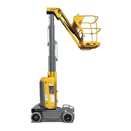
Haulotte STAR 8 Maintenance Book
Aerial work platform
Hide thumbs
Also See for STAR 8:
- Operator's manual (100 pages) ,
- Maintenance book (132 pages) ,
- Operator's manual (114 pages)

Related Manuals for Haulotte STAR 8


Summary of Contents for Haulotte STAR 8
- Page 1 Maintenance book Maintenance book STAR 8 - STAR 22J - STAR 10 - STAR 26J 4000414930 E 10.15 USA / GB...
- Page 2 STAR 8 - STAR 22J - STAR 10 - STAR 26J 4000414930 E 10.15 USA / GB...
-
Page 3: Table Of Contents
2.3 - HAULOTTE Services®........ - Page 4 Maintenance book Familiarization 1 - Primary machine components ... . 1.1 - Layout............1.2 - Ground control box .
- Page 5 Return cables ......MS0053 - Specific adjustment procedure STAR 8 - MS0054 - STAR 20J - STAR 10 - STAR 26J ....
- Page 6 Maintenance book Trouble shooting and diagram 1 - Trouble shooting ..... . 1.1 - Recommendations......... . . 1.2 - Description .
-
Page 7: Preface - Foreword
Only the specifications in this manual should be used to study the suitability of the equipment for the intended use. This maintenance and repairs book is specific to the HAULOTTE® products listed on the cover page of this manual. The maintenance book is intended for the on-site maintenance technician. -
Page 8: Symbols And Colors
STAR 8 - STAR 22J - STAR 10 - STAR 26J - Preface - Foreword 1 - Symbols and colors Symbols and colors are used to alert the operator of safety precautions and/or to highlight important safety information. The following safety symbols are used throughout this manual to indicate specific hazards and the hazard severity level when operating or maintaining the Aerial Work Platform. - Page 9 STAR 8 - STAR 22J - STAR 10 - STAR 26J - Preface - Foreword D e c a l s Color Title Description Danger : Indicates a hazardous situation which if not avoided, WILL result in death or serious injury.
- Page 10 STAR 8 - STAR 22J - STAR 10 - STAR 26J - Preface - Foreword Notes 4000414930 E 10.15 USA / GB...
-
Page 11: Safety
STAR 8 - STAR 22J - STAR 10 - STAR 26J - Safety Safety 1 - General safety rules 1.1 - MAINTENANCE IMPLEMENTATION Your safety and the safety of the people around are essential. Make sure the work area is clean in order to not to pollute the system of the machine. -
Page 12: Electrocution Hazards
STAR 8 - STAR 22J - STAR 10 - STAR 26J - Safety 1.3 - ELECTROCUTION HAZARDS The machine is not electrically insulated and does not provide protection from contact or proximity to electrically charged conductors. Always position the lift at a safe distance from electrically charged conductors to ensure that no part of the machine is within an unsafe area. -
Page 13: Explosion / Fire Hazards
STAR 8 - STAR 22J - STAR 10 - STAR 26J - Safety 1.4 - EXPLOSION / FIRE HAZARDS Always wear protective clothing and eye wear when working with batteries and power sources/systems. N.B.-:-A CID IS NEUTRALIZED WITH SODIUM BICARBONATE AND WATER •... -
Page 14: Maintenance And Repair Training
Only authorized and qualified operators may operate HAULOTTE® machines. 2.3 - HAULOTTE SERVICES® The HAULOTTE Group is at your service in all 5 continents of the world via an extensive network of its own factory trained technicians, who are ready to respond to your every need. -
Page 15: Product Modification
HAULOTTE Services®. Do not hesitate to contact HAULOTTE Services® , should you have any questions relating to the issued bulletin(s) or with questions on the policy itself. -
Page 16: Manufacturer's Warranty
• If damage is caused by modifications that do not comply with HAULOTTE® specifications. • If lubricants, hydraulic oils or fuels that do not comply with HAULOTTE® recommendations are used. • If the machine is incorrectly repaired or used by the customer. -
Page 17: Warranty Conditions
HAULOTTE® will not accept any claims concerning cleaning of the fuel circuit, filter, injection pump or any other equipment in direct contact with fuel or lubricants. - Page 18 STAR 8 - STAR 22J - STAR 10 - STAR 26J - Safety Notes 4000414930 E 10.15 USA / GB...
- Page 19 STAR 8 - STAR 22J - STAR 10 - STAR 26J - Familiarization Familiarization Notes 4000414930 E 10.15 USA / GB...
-
Page 20: Primary Machine Components
STAR 8 - STAR 22J - STAR 10 - STAR 26J - Familiarization 1 - Primary machine components 1.1 - LAYOUT S T A R S T A R 2 2 J S T A R S T A R... - Page 21 STAR 8 - STAR 22J - STAR 10 - STAR 26J - Familiarization Marking Description Marking Description Chassis Telescopic mast Cable reel Platform Pothole protection Platform control box Hinged midrail Slew ring Tilt sensor Turntable assembly Guardrail Tie-down (and/or forklift loading)
-
Page 22: Ground Control Box
STAR 8 - STAR 22J - STAR 10 - STAR 26J - Familiarization 1.2 - GROUND CONTROL BOX 1.2.1 - Layout G e n e r a l v i e w C o n t r o l s... -
Page 23: Activ'screen
STAR 8 - STAR 22J - STAR 10 - STAR 26J - Familiarization 1.2.2 - ACTIV'Screen I n d i c a t o r s ACTIV’Screen 4000274010 B Marking Description Platform overload indicator : Intermittently lit in case of overload 'Enable Switch' selector : Press and hold 'Enable switch' button "Overriding system"... -
Page 24: Platform Control Box
STAR 8 - STAR 22J - STAR 10 - STAR 26J - Familiarization 1.3 - PLATFORM CONTROL BOX 1.3.1 - Layout G e n e r a l v i e w 4000414930 E 10.15 USA / GB... - Page 25 STAR 8 - STAR 22J - STAR 10 - STAR 26J - Familiarization C o n t r o l s a n d i n d i c a t o r s Marking Description Function Tilt indicator Machine on excessive slope...
-
Page 26: Device Layout
STAR 8 - STAR 22J - STAR 10 - STAR 26J - Familiarization 2 - Device layout 2.1 - SENSORS AND ACTUATORS S e n s o r s a n d a c t u a t o r s 4000414930 E 10.15... -
Page 27: Consumables
STAR 8 - STAR 22J - STAR 10 - STAR 26J - Familiarization Description Name Starting up centralized battery refilling SA911 Pressure transducers SP600 Position sensor mast lowered SQ530 Position sensor mast raised SQ534 Sensor - Tilt 3° SQ800 Sensor - chain tension detection 1... -
Page 28: Ingredient
STAR 8 - STAR 22J - STAR 10 - STAR 26J - Familiarization 4 - Ingredient Ingredient HAULOTTE® code Hydraulic oil 2420801310 Hydraulic oil (Winter option) 2505002640 Biological hydraulic oil 2820304310 4.1 - HYDRAULIC OIL Hydraulic oils must comply with the following requirements : •... -
Page 29: Lubrication Diagram
STAR 8 - STAR 22J - STAR 10 - STAR 26J - Familiarization 5 - Lubrication diagram DANGER L i s t i n g r e d i e n t s Marking Ingredient Symbol HAULOTTE® code Hydraulic oil (Standard) - Barrel 209 l(55,2 gal US) -
Page 30: Greasing Points Localization
STAR 8 - STAR 22J - STAR 10 - STAR 26J - Familiarization 5.1 - GREASING POINTS LOCALIZATION • Slew ring. • Wheel axles : 2 on the chassis. Lubricate the pivots with lead-free grease. • Mast lubrication : 4000414930 E 10.15... -
Page 31: Machine Specifications
STAR 8 - STAR 22J - STAR 10 - STAR 26J - Familiarization 6 - Machine specifications 6.1 - MOVEMENT SPEED To allow checking operation, refer to the following table about originally time per movement. If the values measured by test are not equal to the following : •... - Page 32 STAR 8 - STAR 22J - STAR 10 - STAR 26J - Familiarization Notes 4000414930 E 10.15 USA / GB...
-
Page 33: Inspection And Maintenance Schedule
STAR 8 - STAR 22J - STAR 10 - STAR 26J - Inspection and maintenance schedule Inspection and maintenance schedule 1 - Maintenance Schedule There are a number of factors which can affect the design life including but not limited to, severity of operating conditions/routine maintenance. - Page 34 STAR 8 - STAR 22J - STAR 10 - STAR 26J - Inspection and maintenance schedule Intervals Area After 125 h After 250 h After 1500 h After 5000 h Daily (hours) or 1 year (hours) or 1 year (hours) or 3 years...
- Page 35 STAR 8 - STAR 22J - STAR 10 - STAR 26J - Inspection and maintenance schedule Intervals Area After 125 h After 250 h After 1500 h After 5000 h Daily (hours) or 1 year (hours) or 1 year (hours) or 3 years...
- Page 36 STAR 8 - STAR 22J - STAR 10 - STAR 26J - Inspection and maintenance schedule Intervals Area After 125 h After 250 h After 1500 h After 5000 h Daily (hours) or 1 year (hours) or 1 year (hours) or 3 years...
-
Page 37: Inspection Program
Country of use but no less than once a year. The purpose of the inspection is to detect any defect which could lead to an accident during routine use of the machine. HAULOTTE Services® requires Reinforced and Major Inspections to be carried out on the product to extend its service life. -
Page 38: Daily Inspection
STAR 8 - STAR 22J - STAR 10 - STAR 26J - Inspection and maintenance schedule 3 - Daily inspection The content and method of inspection must be conducted by operators before using the machine, it includes a visual inspection and functional and security systems testing of the machine. - Page 39 STAR 8 - STAR 22J - STAR 10 - STAR 26J - Inspection and maintenance schedule Daily inspection Visual inspection without disassembly Check level To check by test Corrected applicable Manuals and displays. Clean or replace if necessary. Presence, cleanliness and legibility of the...
- Page 40 STAR 8 - STAR 22J - STAR 10 - STAR 26J - Inspection and maintenance schedule Extending structure (jib, mast) No cracks, broken weld, paint chipped No deterioration and visible damage No screws missing / loose parts No foreign material / impurities in joints or slides...
- Page 41 STAR 8 - STAR 22J - STAR 10 - STAR 26J - Inspection and maintenance schedule Battery electrolyte level Level of centralized battery refilling No screws missing / loose parts Presence and good condition of hydraulic hose Presence and good condition of engine components Presence and good condition of the batteries: terminations and clamps, electrolyte level ...
-
Page 42: Periodic Inspection
Otherwise or in addition, use the detailed program below. This inspection is the responsibility of the owner, and must be conducted by a qualified technician. To ensure safe use and improve the life of machine, HAULOTTE® recommends performing this inspection at every 125 hours intervals. - Page 43 STAR 8 - STAR 22J - STAR 10 - STAR 26J - Inspection and maintenance schedule Periodic inspection In addition to the daily inspection program Area Type of intervention Area Type of intervention Mast assembly Functions and controls Platform control box (indicators, Chains etc.)
-
Page 44: Reinforced Inspection
Reinforced periodic inspection is a thorough inspection of the machine structure and to ensure proper functionality. It must be performed every 1500 h or every 3 years, whichever occurs first. This inspection is the responsibility of the owner, and it must be conducted by a HAULOTTE Services® technician or a qualified company or person. - Page 45 STAR 8 - STAR 22J - STAR 10 - STAR 26J - Inspection and maintenance schedule Reinforced inspection In addition to daily and periodic inspections Area Type of intervention Area Type of intervention Mast assembly Functions and controls Platform control box (indicators, Chains etc.)
-
Page 46: Major Inspection
5 years, whichever occurs first, and subsequently every 5 years thereafter. This inspection is the responsibility of the owner, and it must be conducted by a HAULOTTE Services® technician or by a qualified and authorized company or person. - Page 47 STAR 8 - STAR 22J - STAR 10 - STAR 26J - Inspection and maintenance schedule Major inspection In addition with daily, periodic, and reinforced inspections Area Type of intervention Area Type of intervention Platform assembly Functions and controls Platform control box (indicators, Platform etc.)
- Page 48 STAR 8 - STAR 22J - STAR 10 - STAR 26J - Inspection and maintenance schedule Machine sheet N.B.-:-T HAULOTTE HE LIST OF AINTENANCE NSPECTION HEETS IS NOT EXHAUSTIVE ONTACT ® ERVICES FOR ADDITIONAL OTHER SHEETS 4000414930 E 10.15 USA / GB...
-
Page 49: Structural Part Inspection
General data Structural part inspection MS0001 General data Structural part inspection 1 - You will need • Standard tool kit • Protective goggles • Place barriers around the perimeter of the work area • Gloves Exclusively use tools and auxiliary average adapted. Always wear necessary safety clothing. For safety reasons, imperatively respect the following stages during the tests : •... - Page 50 General data Structural part inspection MS0001 3 - Control and maintenance To guarantee the integrity of the machine, it is necessary to carry out periodical controls on the mechanical structure such as defines hereafter. 3.1 - DAILY INSPECTION All the accessible structural part without disassembling must be subjected to a fast visual inspection.
- Page 51 General data Structural part inspection MS0001 3.2 - MAJOR INSPECTION A thorough inspection of the structural parts must be realized all the 5000 h or 10 years with disassembling of the element to check the entirety of the welding. All structural part listed Section Familiarization must be disassembled and all weldsmust be review using non-destructive checks.
- Page 52 If the difference between two measurements does not exceed 4 cm (1.575 in) : the test is validated. If the difference between two measurements exceeds 4 cm (1.575 in), to contact HAULOTTE Services® or to carry out the additional tests described below.
-
Page 53: Pins And Bearing Inspection
General data Pins and bearing inspection MS0002 General data Pins and bearing inspection 1 - You will need • Standard tool kit • Protective goggles • Place barriers around the perimeter of the work area • Gloves Exclusively use tools and auxiliary average adapted. Always wear necessary safety clothing. 2 - Preliminary operation The operations of disassembling if they exist should be carried out only on the installations completely disconnected and must be entrusted only to people having the necessary technical training. - Page 54 General data Pins and bearing inspection MS0002 3 - Control and maintenance The control of pins, stop pins, bushes and bearing must be carried out according to the following recommendations : • Every day before use : Fast visual inspection without disassembling. •...
- Page 55 General data Pins and bearing inspection MS0002 5 - Procedure of reassembly 5.1 - PINS AND BUSHES For OPTIMUM 8 - OPTIMUM 1931 E only : Never grease the pins and rings of scissor arms. When reassembling bearings and pins ensure that : •...
- Page 56 General data Pins and bearing inspection MS0002 5.2 - BEARINGS For the reassembly of bearings, respect the following stages : • Clean boring and/or the pins to remove all the foreign bodies. • Slightly lubricate boring and/or pins. • Lubricate the ring of the bearing slightly. •...
-
Page 57: Cylinder Inspection
General data Cylinder inspection MS0003 General data Cylinder inspection 1 - You will need • Standard tool kit • Protective goggles • Place barriers around the perimeter of the work area • Gloves Exclusively use tools and auxiliary average adapted. Always wear necessary safety clothing. For safety reasons, imperatively respect the following stages during the tests : •... - Page 58 • If the difference between two measurements does not exceed 4 cm (1.575 in) : the test validates correct operation. • If the difference between two measurements exceeds 4 cm (1.575 in), contact HAULOTTE Services® or carry out the additional tests described below.
- Page 59 General data Cylinder inspection MS0003 Control cylinder by cylinder : • Position a load equal to the rated capacity on the cage (or platform). • Perform the movement of the concern cylinder to half of its stroke. • Fix the cylinder with a comparator : •...
- Page 60 General data Cylinder inspection MS0003 3.3 - MAJOR INSPECTION A thorough inspection of the structural parts must be realized all the 5000 h or 10 years with disassembling of the element to check the entirety of the welding. Each Cylinder must be disassembled and must be review using non-destructive checks.
-
Page 61: Breaking Test Procedure
• Stopped machine, measure the distance between the wheel axles and traced reference mark on the ground : • If the distance lies between 0.2 m (0ft 8in) and 2,7 m (8 ft 11 in), the test is validated. • If not, Contact HAULOTTE Services® to repair the system. 4000414930 E 10.15... - Page 62 General data Breaking test procedure MS0004 Notes 4000414930 E 10.15 USA / GB...
-
Page 63: Torque Values
Torque Values 1 - Metric torque chart For screws HAULOTTE®, use columns ( A ), ( B ) and ( C ) : • Screw ( 1 ) grey dull dry, use colums ( A ) • Screw ( 1 ) grey dull greasy, use column ( B ) •... - Page 64 General data Torque Values MS0005 2 - SAE fastener torque chart SAE fastener torque chart This charts is to be used as a guide only unless noted elsewhere in this manual A574 High Grade 5 Grade 8 strength black oxide bolts Size Thread Lubed...
- Page 65 General data Torque Values MS0005 3 - STAR 8 - STAR 22J - STAR 10 - STAR 26J Sub-assemblies Concerned elements Torque Chassis Wheels 32 Nm Wheel studs / Driving reducer Loctite 243 - Normal threadlocker Wheel axles 115 Nm...
- Page 66 General data Torque Values MS0005 Notes 4000414930 E 10.15 USA / GB...
-
Page 67: Slew Ring Inspection
Chassis and turntable Slew ring inspection MS0010 Chassis and turntable Slew ring inspection 1 - You will need • Standard tool kit • Protective goggles • Place barriers around the perimeter of the work area • Gloves Exclusively use tools and auxiliary average adapted. Always wear necessary safety clothing. For safety reasons, imperatively respect the following stages during the tests : •... - Page 68 Chassis and turntable Slew ring inspection MS0010 3 - Lubrication The maintenance of the slew ring is essential for the safety of the machine and to guarantee its service life. Whatever the type of system installed on the machine, interior or external teeth, follow the recommendations of greasing as indicated in the program.
- Page 69 158.6 lb ft STAR 8 - STAR 22J - Ring on plate 135 Nm 100 lb ft STAR 8 - STAR 22J - Plate on mast foot 195 Nm 144 lb ft STAR 8 - STAR 22J - Ring on chassis...
- Page 70 • Check the appearance of the teeth. A tight spot or grinding sound during rotation or the presence of metal particles escaping from the lip seal are signs of abnormal wear in the raceway (Contact HAULOTTE Services®). Replace slew ring in the following cases : •...
- Page 71 In its new configuration, note the clearance ( J1) between chassis (or turret) and the slew ring as previously. • If the difference between two measurements does not exceed 2 mm (0.08 in) : the test validates correct operation. • Otherwise, contact HAULOTTE Services® to repair the system. 4000414930 E 10.15...
- Page 72 Chassis and turntable Slew ring inspection MS0010 Notes 4000414930 E 10.15 USA / GB...
-
Page 73: Condition Of The Cables Inspection - Criteria Of Replacement
After completion of work, all the covers and safety devices must be positioned back completely and operational. 3 - Control wire rope system To guarantee a full safety use of the machine , Haulotte recommends respecting the following inspections : 3.1 - DAILY CHECK •... - Page 74 • Check that the cable is properly seated in the pulley. • Check that nothing blocks the chain guides. • Check the condition of the cables. If any of the following defects are observed, replace the pair of cables. Replace defective parts with genuine HAULOTTE® replacements. 4000414930 E 10.15...
- Page 75 Condition of the cables inspection - Criteria of replacement MS0012 Machine Original diameter STAR 6 - STAR 13 - STAR 8 - STAR 22J - STAR 10 - STAR 22J 3 mm H21TX - H23TPX - H25TPX 9 mm HA16JRT...
- Page 76 • for STAR all 250 hours or 3 months. • for the other machines all 250 h hours or 6 months. For the particular procedures of adjustment untreated in maintenance book, it is necessary to contact HAULOTTE Services®. MS0018 Boom adjustment procedure.
-
Page 77: Hoses Inspection - Replacement
Hydraulics Hoses inspection - Replacement MS0020 Hydraulics Hoses inspection - Replacement 1 - You will need • Standard tool kit • Protective goggles • Place barriers around the perimeter of the work area • Gloves Exclusively use tools and auxiliary average adapted. Always wear necessary safety clothing. 2 - Control and inspections The state of hoses devices plays a significant role in the safety of the machines. - Page 78 Hydraulics Hoses inspection - Replacement MS0020 3 - Hoses Disassembling For safety reasons, respect imperatively the following conditions of disassembling : • Fold the machine on a flat and released ground : • The machine is not in slope. • The boom is horizontal. •...
-
Page 79: Electrical Wiring
Electric Electrical wiring MS0059 Electric Electrical wiring 1 - You will need • Standard tool kit • Protective goggles • Place barriers around the perimeter of the work area • Gloves Exclusively use tools and auxiliary average adapted. Always wear necessary safety clothing. Maintaining electrical wiring in good condition is essential to safe operation and good machine performance. - Page 80 Electric Electrical wiring MS0059 Notes 4000414930 E 10.15 USA / GB...
-
Page 81: Inspection Of The Condition Of The Chains - Criteria Of Replacement
Upper boom Inspection of the condition of the chains - Criteria of replacement MS0042 Upper boom Inspection of the condition of the chains - Criteria of replacement 1 - You will need • Standard tool kit • Protective goggles • Place barriers around the perimeter of the work area •... - Page 82 • Measure the value of (3) using an appropriate method. Compare with the value of *1 indicated in the table below. Machine Link width (2) Length of 12 links (4) STAR 6 - STAR 13 - STAR 8 - STAR 22J - STAR 10 - STAR 26J HA32/41PX-NT 11.5 mm 152.40 mm H28TJ+/H43TPX STAR 8 - STAR 22J - STAR 10 - STAR 26J 14.50 mm...
- Page 83 Upper boom Inspection of the condition of the chains - Criteria of replacement MS0042 • Check for external wear on rollers and links : • External wear must not measure more than 2 % from the section of the original link (2), see table above. •...
- Page 84 3.2 - CHECK THE TENSION OF THE CHAINS Refer to the technical data sheet for your product following this sheet. To make any other adjustments not detailed in this maintenance logbook : Contact Haulotte Services for further advice. 4 - Replacing the chains The chains must imperatively be changed every 10 years.
-
Page 85: Tires (Tyres) And Pressures - Wheel Replacement
Chassis and turntable Tires (Tyres) and pressures - Wheel replacement MS0044 Chassis and turntable Tires (Tyres) and pressures - Wheel replacement 1 - You will need • Standard tool kit • Protective goggles • Gloves • Place barriers around the perimeter of the work area •... - Page 86 • Consistent wear of the ground contact surface greater than 25% Tires and rims are critical components for the stability of the machine. For safety reasons. : • Use only HAULOTTE® spare parts according to the technical characteristics of the machine. Refer to the spare parts catalog.
- Page 87 Chassis and turntable Tires (Tyres) and pressures - Wheel replacement MS0044 5 - Wheel replacement Procedure of replacement : • Loosen the wheel nuts on the wheel to be removed. • Raise the machine using a jack or a hoist. •...
- Page 88 Chassis and turntable Tires (Tyres) and pressures - Wheel replacement MS0044 Notes 4000414930 E 10.15 USA / GB...
-
Page 89: Lubrication - Jib Cylinder - Steering Cylinder - Lift Cylinder
Chassis and turntable Lubrication - Jib cylinder - Steering cylinder - Lift cylinder MS0045 Chassis and turntable Lubrication - Jib cylinder - Steering cylinder - Lift cylinder 1 - You will need • Standard tool kit • Brush • Multipurpose grease (of mineral type) •... - Page 90 Chassis and turntable Lubrication - Jib cylinder - Steering cylinder - Lift cylinder MS0045 3 - Lubrication Jib cylinder In order to maintain the lifting cylinder in good condition and avoid any internal or external corrosion during prolonged storage (inside or outside), proceed as follows : •...
- Page 91 Chassis and turntable Lubrication - Jib cylinder - Steering cylinder - Lift cylinder MS0045 Steering cylinder In order to maintain the lifting cylinder in good condition and avoid any internal or external corrosion during prolonged storage (inside or outside), proceed as follows : •...
- Page 92 Chassis and turntable Lubrication - Jib cylinder - Steering cylinder - Lift cylinder MS0045 Lift cylinder In order to maintain the lifting cylinder in good condition and avoid any internal or external corrosion during prolonged storage (inside or outside), proceed as follows : •...
-
Page 93: Dismantling / Reassembling Wheels Reducer
It is important that the person performing the work on the machine knows all the relative safety information contained in the instruction manual. Only an authorized and qualified technician can work on HAULOTTE® machines. 3 - Safety instructions • The technician should take all steps to protect themselves or others against all risks of injury related to this intervention. - Page 94 Chassis and turntable Dismantling / Reassembling wheels reducer MS0046 4 - Removal • Cut off the main power supply at the battery master switch. • Disconnect all energy sources connected to the machine (e.g. battery charger). • Identify the motor to be replaced. Arrière gauche / Arrière droit / Rear right...
- Page 95 Chassis and turntable Dismantling / Reassembling wheels reducer MS0046 • Sling the gear motor assembly using a 500 kg(1100 lb) sling and a bridge crane. N.B.-:-I F THE GEAR MOTOR NEEDS TO BE DISMANTLED UNSCREW THE FASTENING SCREWS 4000414930 E 10.15 USA / GB...
- Page 96 Chassis and turntable Dismantling / Reassembling wheels reducer MS0046 5 - Reinstall • Reposition the assembly in the notch. • Push the motor into the highest position. • Attach the assembly using screws and washers. • Tighten to the recommended torque : 32 Nm. •...
- Page 97 Chassis and turntable Dismantling / Reassembling wheels reducer MS0046 • Tighten to the recommended torque on the above procedure (4,8 Nm). • Refit the wheel. • Attach the wheel using the 5 screws and washers. • Tighten to the recommended torque : 115 Nm. •...
- Page 98 Chassis and turntable Dismantling / Reassembling wheels reducer MS0046 Notes 4000414930 E 10.15 USA / GB...
-
Page 99: Replacing The Wheel Pivot
It is important that the person performing the work on the machine knows all the relative safety information contained in the instruction manual. Only an authorized and qualified technician can work on HAULOTTE® machines. 3 - Safety instructions • The technician should take all steps to protect themselves or others against all risks of injury related to this intervention. - Page 100 Chassis and turntable Replacing the wheel pivot MS0047 4 - Removal The procedure is identical for the front left and front right pivots. F r o n t r i g h t p i v o t F r o n t l e f t p i v o t •...
- Page 101 Chassis and turntable Replacing the wheel pivot MS0047 • Lift the machine using a hoist (or a jack). Place chocks under the chassis to ensure the machine is safely immmobilised. • Remove the V4X45 pin and M18 flat washer. • Unscrew the fastening plate from the steering pivots (right or left depending on the pivot to be changed).
- Page 102 Chassis and turntable Replacing the wheel pivot MS0047 L e f t s t o p ( S c r e w r i n g H E 6 X 1 6 ) R i g h t s t o p ( S c r e w r i n g C H C 6 X 1 6 )
- Page 103 Chassis and turntable Replacing the wheel pivot MS0047 5 - Reinstall 5.1 - HUB • Lubricate the interior of the 2 bores. V i e w f r o m l a r g e b o r e s i d e V i e w f r o m s m a l l...
- Page 104 Chassis and turntable Replacing the wheel pivot MS0047 • Lubricate the inner and outer rings and slide the assembly into the cage, as shown. • Fit the seal into its seating. Take care it is mounted the right way round. •...
- Page 105 Chassis and turntable Replacing the wheel pivot MS0047 • Slide on the wheel hub. • Using a punch, insert the wheel hub up to the stop. Do not force it. • Using a punch, insert the small bearing into its cage. 4000414930 E 10.15 USA / GB...
- Page 106 Chassis and turntable Replacing the wheel pivot MS0047 • Position the M30 washer in the centre. • Screw up the nut. • Tighten with a torque wrench to a torque of 10 Nm. N.B.-:-I F NECESSARY FINISH TIGHTENING WITH A RATCHET WRENCH TO LINE UP THE HOLE FOR THE PIN •...
- Page 107 Chassis and turntable Replacing the wheel pivot MS0047 5.2 - WHEEL AXLES • Lubricate the shaft of the pivot. • Apply grease to the 2 sides of the washer. • Position the washer at the stop. • Position the chamfer on the top as shown. •...
- Page 108 Chassis and turntable Replacing the wheel pivot MS0047 • Re-attach the stops (right and left). • Refit the wheel. • Tighten to the recommended torque : 115 Nm. • Lower the machine to the ground. • Tighten the wheel nuts to the recommended torque : 115 Nm 6 - Checks •...
-
Page 109: Steering Cylinder Replacement
It is important that the person performing the work on the machine knows all the relative safety information contained in the instruction manual. Only an authorized and qualified technician can work on HAULOTTE® machines. 3 - Safety instructions • The technician should take all steps to protect themselves or others against all risks of injury related to this intervention. - Page 110 Chassis and turntable Steering cylinder replacement MS0048 4 - Removal • Cut off the main power supply at the battery master switch. • Disconnect all energy sources connected to the machine (e.g. battery charger). • Remove the covers. • Lift the machine using a hoist (or a jack). •...
- Page 111 Chassis and turntable Steering cylinder replacement MS0048 • Remove the 4 HM12x40 cl 10.8 fastening screws using a 16 mm diameter wrench in order to remove the cylinder assembly and the 2 steering tie-rods. • Extend the cylinder. • Remove the V4X45 pin and the M16 flat washer from each side. •...
- Page 112 Chassis and turntable Steering cylinder replacement MS0048 5 - Reinstall • Refit the tie-rods. Take care that the yoke shoulder is the right way round. • Re-build the actuator. • Attach the cylinder to the wheel pivots. • Refit the wheels. •...
-
Page 113: Hydraulic Oil - Level Replacement
Hydraulics Hydraulic oil - Level Replacement MS0049 Hydraulics Hydraulic oil - Level Replacement 1 - You will need • Standard tool kit • Place barriers around the perimeter of the • Protective goggles work area • Gloves Exclusively use tools and auxiliary average adapted. Always wear necessary safety clothing. 2 - Preliminary operation For safety reasons, imperatively respect the following stages during the tests : •... - Page 114 • Check the absence of rubber, plastic or metal shaving. 4.1 - CONSUMABLE Use only oils whose features correspond to HAULOTTE® recommendations (Section C - Familiarization - Consumable) or contact HAULOTTE Services®. Not mix two different characteristics oils. If necessary, purge and clean the circuit.
-
Page 115: Hydraulic Filter Cartridge Replacement
Hydraulics Hydraulic filter cartridge Replacement MS0050 Hydraulics Hydraulic filter cartridge Replacement 1 - You will need • Standard tool kit • Protective goggles • Place barriers around the perimeter of the work area • Gloves Exclusively use tools and auxiliary average adapted. Always wear necessary safety clothing. All hydraulic components (pump, tanks….) except cylinders must be subjected to periodic visual inspections such as defined below. - Page 116 Hydraulics Hydraulic filter cartridge Replacement MS0050 Notes 4000414930 E 10.15 USA / GB...
-
Page 117: Battery (Ies)
Electric Battery (ies) MS0051 Electric Battery (ies) 1 - You will need • Standard tool kit • Protective goggles • Place barriers around the perimeter of the work area • Gloves Exclusively use tools and auxiliary average adapted. Always wear necessary safety clothing. 2 - Control Remove the battery cover. - Page 118 Electric Battery (ies) MS0051 3 - Centralized battery refilling The machine is delivered with the centralized filling tank empty. When using the machine for the first time, the user must fill the tank with demineralized water up to the maximum level. •...
- Page 119 Electric Battery (ies) MS0051 4 - Filling the batteries manually In cold weather conditions, centralized battery filling does not function. Perform battery filling manually. Loosen the caps located on the top of the battery. If the level of electrolyte is below the level of the plates : Top up with distilled water.
- Page 120 • The charger settings are adjusted in the factory using its own cable. If the cable needs changing, the HAULOTTE® factory must be contacted to obtain authorisation. How to charge the batteries ? : Before charging the batteries, switch the machine off.
- Page 121 Electric Battery (ies) MS0051 When there is a fault, the LED indicator flashes in various colours depending on the type of alarm : State of flashing indicator Type of alarm Description (Action) Battery not connected or not compliant : Check connection or Battery presence rated voltage.
- Page 122 Electric Battery (ies) MS0051 B a t t e r y c h a r g e s t a t u s a c c o r d i n g d e n s i t y a n d t e m p e r a t u r e Do not store machines, outside and in cold weather conditions, when batteries are discharged : Risk of damaging batteries.
- Page 123 Electric Battery (ies) MS0051 L o s s c a p a c i t y d u r i n g p r o l o n g e d s t o r a g e .0015 perdu par semaine lors d'un stockage à une T° de 6°C .0015 per week loss in prolonged storage at 42°F .005 perdu par semaine lors d'un stockage à...
- Page 124 Electric Battery (ies) MS0051 Notes 4000414930 E 10.15 USA / GB...
-
Page 125: Battery (Ies)
It is important that the person performing the work on the machine knows all the relative safety information contained in the instruction manual. Only an authorized and qualified technician can work on HAULOTTE® machines. 3 - Safety instructions • The technician should take all steps to protect themselves or others against all risks of injury related to this intervention. - Page 126 Electric Battery (ies) MS0052 4 - Removal • Lift the mast slightly. • Cut off the main power supply at the battery master switch. • Disconnect all energy sources connected to the machine (e.g. battery charger). O v e r v i e w B a t t e r i e s •...
- Page 127 Electric Battery (ies) MS0052 • Disconnect all the cables connected to the battery elements. • Disconnect the centralized filling pipes. • Loosen and remove the 2 fastening screws . • Remove the upper cover bracket. • Remove the battery compartment using a bridge crane. 4000414930 E 10.15 USA / GB...
- Page 128 Electric Battery (ies) MS0052 5 - Reinstall • Refit a the new battery pack. • Re-attach and reconnect all the cables and pipes to the centralized filling system. Take care with the connections. • Switch the machine on. • Check the levels and top up as required. •...
-
Page 129: Return Cables
It is important that the person performing the work on the machine knows all the relative safety information contained in the instruction manual. Only an authorized and qualified technician can work on HAULOTTE® machines. 3 - Safety instructions • The technician should take all steps to protect themselves or others against all risks of injury related to this intervention. - Page 130 Mast Return cables MS0053 4 - Control on STAR 8 - STAR 22J and STAR 10 - STAR 22J only : Replace in case of : • Broken wire ( C ) • Broken strand ( B ) • Kinked cable 1 mm max.
-
Page 131: Specific Adjustment Procedure Star 8 - Star 20J - Star 10 - Star 26J
Mast Specific adjustment procedure STAR 8 - STAR 20J - STAR 10 - STAR 26J MS0054 Mast Specific adjustment procedure STAR 8 - STAR 20J - STAR 10 - STAR 26J 1 - You will need • PPE (Personal Protective Equipment: glove, safety shoe, glasses, etc…) - Page 132 Mast Specific adjustment procedure STAR 8 - STAR 20J - STAR 10 - STAR 26J MS0054 4 - Inspection of chain adjustment From the ground control box : • Lift the mast so that tube 1 extends 300 mm beyond the foot of the mast (+/- 2 mm).
- Page 133 Mast Specific adjustment procedure STAR 8 - STAR 20J - STAR 10 - STAR 26J MS0054 • If not compliant : Carry out the operations from the ground control box. Before adjusting the chains, check that the return cables are not tight.
- Page 134 • Lift the mast so that tube 1 extends 100 mm beyond the foot of the mast (+/- 20 mm). 100 mm +/- 20 mm Inspect the 6 return cables ( 4 for the STAR 8). The clearance between the washer and the foot of the mast or tube must be 2 mm.
- Page 135 Mast Specific adjustment procedure STAR 8 - STAR 20J - STAR 10 - STAR 26J MS0054 2 mm • If not compliant : For the cables at the foot of the mast and tube 1 : • Hold the cable lub with a 4 flat wrench •...
- Page 136 Mast Specific adjustment procedure STAR 8 - STAR 20J - STAR 10 - STAR 26J MS0054 Notes 4000414930 E 10.15 USA / GB...
-
Page 137: Tube Wedging Procedure
It is important that the person performing the work on the machine knows all the relative safety information contained in the instruction manual. Only an authorized and qualified technician can work on HAULOTTE® machines. 3 - Safety instructions • The technician should take all steps to protect themselves or others against all risks of injury related to this intervention. - Page 138 Mast Tube wedging procedure MS0061 4 - Procedure Wedging of the folded mast must be carried out with a functional clearance of 1 mm in the left/right axis and 0,5 mm in the front/rear axis. If the mast jams when being extended, increase the clearance. Avant / Front Gauche / Left Droite / Right...
-
Page 139: Inspection Of The Slack Chain Sensors
It is important that the person performing the work on the machine knows all the relative safety information contained in the instruction manual. Only an authorized and qualified technician can work on HAULOTTE® machines. 3 - Safety instructions • The technician should take all steps to protect themselves or others against all risks of injury related to this intervention. - Page 140 Mast Inspection of the slack chain sensors MS0062 4 - Procedure • Lift the machine to a height of 1 m(3 ft3 in) using a hoist. Sensor SQ801 : • Place an insulating element between the sensor and the chain rod. •...
- Page 141 Mast Inspection of the slack chain sensors MS0062 5 - Slack chain detector adjustment procedure Installation of the SQ801 and SQ802 detectors S Q 8 0 1 ( L e f t ) S Q 8 0 2 ( R i g h t ) 4000414930 E 10.15 USA / GB...
- Page 142 Mast Inspection of the slack chain sensors MS0062 F i g u r e Distance between the edge of the sensor and the Belleville washers : 5 mm F i g u r e Distance between the edge of the sensor and the Belleville washers : 3 mm Adjustment : •...
- Page 143 Mast Inspection of the slack chain sensors MS0062 The oblong holes must be reduced in height so that the bottom position is not permitted. N.B.-:-T 90 % HE DETECTOR CONNECTORS MUST BE AT AND NOT STRAIGHT AS THEY TOUCH THE SLEW RING Detection of the washers whatever the position of the threaded rod : The detectors remain on even if the threaded rod is completely to the left (1 mm) or right (5 mm).
- Page 144 Mast Inspection of the slack chain sensors MS0062 Notes 4000414930 E 10.15 USA / GB...
-
Page 145: Overriding Function Reset
It is important that the person performing the work on the machine knows all the relative safety information contained in the instruction manual. Only an authorized and qualified technician can work on HAULOTTE® machines. 3 - Preliminary operation The operations of disassembling if they exist should be carried out only on the installations completely disconnected and must be entrusted only to people having the necessary technical training. - Page 146 Overriding system Overriding function reset MS0085 4 - Overriding function reset If the Overriding function has been requested, the machine displays the following screen at startup : 4.1 - PROCEDURE • Enter the access code level 2 or 3. • Select the menu : 3. Machine settings. •...
- Page 147 Overriding system Overriding function reset MS0085 • Enter menu "Option settings". • Move down to the line "Emergency mode not reset". • Press the button to deselect the option. • Return to the welcome screen. The Overriding function is reset. 4000414930 E 10.15 USA / GB...
- Page 148 Overriding system Overriding function reset MS0085 Notes 4000414930 E 10.15 USA / GB...
- Page 149 STAR 8 - STAR 22J - STAR 10 - STAR 26J - Trouble shooting and diagram Trouble shooting and diagram 1 - Trouble shooting 1.1 - RECOMMENDATIONS If a malfunction occurs, check the following points : • Sufficient hydraulic oil in the tank.
- Page 150 STAR 8 - STAR 22J - STAR 10 - STAR 26J - Trouble shooting and diagram Failure Code Description F01 : Inverter Zapi failure code 17 on Combiacx Zapi failure code 23 on Combiacx Zapi failure code 31 on Combiacx Inverter Master F01.01 (A)
- Page 151 STAR 8 - STAR 22J - STAR 10 - STAR 26J - Trouble shooting and diagram Failure Code Description F04 : Electrovalves Steering front left valve YV150L failure (short circuit) and steering setpoint active - YV150L = FAIL & STP (Steering) Steering F04.01 (D)
- Page 152 STAR 8 - STAR 22J - STAR 10 - STAR 26J - Trouble shooting and diagram Failure Code Description F07 : Sensors SQ801 = 1 Broken Chain F07.02 (D) SB801/SB802 SQ802 = 1 Zapi failure code 61 on Combiacx Motor Temperature F07.05 (D)
- Page 153 STAR 8 - STAR 22J - STAR 10 - STAR 26J - Trouble shooting and diagram Failure Code Description F12 : Internal faults Cantiller RX failure Screen RX failure Zapi failure code 39 on Combiacx or no information received CAN Fault F12.01 (A)
- Page 154 STAR 8 - STAR 22J - STAR 10 - STAR 26J - Trouble shooting and diagram Failure Code Description F13 : Switches Incoherence between the 2 signals of jib lifting switch of turret box (both active) • SA620U = 1 & SA620D = 1...
- Page 155 STAR 8 - STAR 22J - STAR 10 - STAR 26J - Trouble shooting and diagram Failure Code Description F15 : J1939 Failure J1939 F15.06 (D) Error on J1939 Failure Code Description F16 :Motor Zapi failure code 35 on Combiacx Overheating F16.01 (A)
- Page 156 STAR 8 - STAR 22J - STAR 10 - STAR 26J - Trouble shooting and diagram 2 - Electric diagram E l e c t r i c i t y p a r t 03-17 03-17 03-2 02-1 02-1...
- Page 157 STAR 8 - STAR 22J - STAR 10 - STAR 26J - Trouble shooting and diagram V a r i a b l e s p e e d d r i v e p a r t 01-22 01-22...
- Page 158 STAR 8 - STAR 22J - STAR 10 - STAR 26J - Trouble shooting and diagram C a g e p a r t 4000414930 E 10.15 USA / GB...
- Page 159 STAR 8 - STAR 22J - STAR 10 - STAR 26J - Trouble shooting and diagram 3 - Hydraulic diagram 4000414930 E 10.15 USA / GB...
- Page 160 STAR 8 - STAR 22J - STAR 10 - STAR 26J - Trouble shooting and diagram Notes 4000414930 E 10.15 USA / GB...
- Page 161 STAR 8 - STAR 22J - STAR 10 - STAR 26J - Records Records 1 - Intervention register The intervention register keeps a record of maintenance and repair work carried out inside or outside the maintenance programme. N.B.-:-I HAULOTTE S ®...
- Page 162 STAR 8 - STAR 22J - STAR 10 - STAR 26J - Records Number of HAULOTTE Services® Date Type of intervention Intervenor hours intervention number 4000414930 E 10.15 USA / GB...
- Page 163 STAR 8 - STAR 22J - STAR 10 - STAR 26J - Records Number of HAULOTTE Services® Date Type of intervention Intervenor hours intervention number 4000414930 E 10.15 USA / GB...
- Page 164 STAR 8 - STAR 22J - STAR 10 - STAR 26J - Records Number of HAULOTTE Services® Date Type of intervention Intervenor hours intervention number 4000414930 E 10.15 USA / GB...
- Page 165 STAR 8 - STAR 22J - STAR 10 - STAR 26J - Records Number of HAULOTTE Services® Date Type of intervention Intervenor hours intervention number 4000414930 E 10.15 USA / GB...
- Page 166 STAR 8 - STAR 22J - STAR 10 - STAR 26J - Records Number of HAULOTTE Services® Date Type of intervention Intervenor hours intervention number 4000414930 E 10.15 USA / GB...
Need help?
Do you have a question about the STAR 8 and is the answer not in the manual?
Questions and answers