Advertisement
Advertisement

Summary of Contents for honle LED powerline AC/IC 410
- Page 1 Operating Instructions LED Powerline AC IC #078734DE-EN e...
- Page 2 LED Powerline ACIC Masthead All rights reserved Copyright by Dr. Hönle AG Lochhamer Schlag 1, 82166 Gräfelfing / Munich, Germany Printed in Germany, December 2017 These Operating Instructions and excerpts thereof must not be reprinted or reproduced in any other manner without the explicit written permission of Dr.
-
Page 3: Table Of Contents
Table of contents Warnings and symbols in these operating instructions........4 Description..................... 5 1.1. Characteristics ................5 1.2. Uses ................... 5 1.3. Structure and connection of the unit .......... 6 Safety ......................7 2.1. General notes ................7 2.2. Risk group .................. 7 2.3. -
Page 4: Warnings And Symbols In These Operating Instructions
LED Powerline ACIC Warnings and symbols in these operating instructions These Operating instructions describe the unit, its operation and possible applications. They contain safety information and information on danger points to ensure safe and correct handling of the unit. The following symbols can be found alongside all safety notices in these Operating instructions that indicate points where persons may be at risk. -
Page 5: Description
1. Description The LED Powerline ACIC,is developed for applications requiring high- intensity UV surface radiation. The high-performance UV LED array means that it can be used not only for intermediate drying (pinning) and final drying in printing applications, but also for the curing of varnishes, adhesives and potting compounds. -
Page 6: Structure And Connection Of The Unit
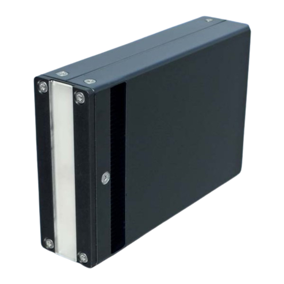
LED Powerline ACIC 1.3. Structure and connection of the unit Structure and connection of the unit Fig. 1: LED Powerline AC IC – rear view Fig. 2: LED Powerline AC IC – frontview (schematic diagram, illustration may vary from the original) Air inlet Fixing thread (4 x M4) SUB-D socket (25-pin) -
Page 7: Safety
2. Safety General notes 2.1. General notes Knowledge of all basic safety regulations is essential to ensure safe han- dling and fault-free operation of the LED Powerline ACIC. The safety notes in these Operating Instructions must be observed by all persons working with the unit. -
Page 8: Intended Use
LED Powerline ACIC 2.3. Intended use Another or additional use of the device, as they explained in the descrip- Intended Use tion, is considered to be improper and dangerous. The unit must not be used for medical or therapeutic purposes, for skin- tanning, or in other medical equipment. -
Page 9: Hazards From Handling The Unit
2.8. Hazards from handling the unit The unit is constructed in accordance with the technological state of the art Dangers from and generally accepted safety engineering practice. Nevertheless, certain Handling the Unit hazards may arise when handling the unit. These always include: ... -
Page 10: Danger From Electrical Current
LED Powerline ACIC 2.8.1.Danger from electrical current The electrical equipment on the unit must be inspected regularly. Inspection before starting work: Check all components of the unit for outwardly visible damage, Check that all electric cable are in flawless condition. Loose connections must be repaired immediately, and damaged cables must be replaced. -
Page 11: Thermal Hazards
2.8.3. Thermal hazards When operating the unit, take the following thermal hazards into account. Thermal hazards When working in the radiation field it is absolutely necessary to wear protective clothing (gloves, protective eyewear). If the reflector is temporarily covered with a visor, ensure adequate ventilation between aperture and filter disc to avoid a heat accumula- tion. -
Page 12: Warranty And Liability
LED Powerline ACIC 2.10. Warranty and liability The Dr. Hönle AG "General Conditions of Sale and Delivery" always apply. Warranty and liability They are available to the operator upon signing the contract, at the latest. No warrants or liability claims may be made in the event of injury to persons or damage to property, in particular if this injury or damage has arisen due to one or more of the following: ... -
Page 13: Transport, Storage, Delivery
3. Transport, Storage, Delivery Scope of Deliv- Scope of Delivery LED Powerline ACIC LED Powerline ACIC Operating Instructions Depending on the agreed scope of delivery, the components are supplied as individual parts or as (a) fully assembled and wired unit(s). The delivered parts must be inspected for completeness and damage or other issues. -
Page 14: Installation, Commissioning And Power-Up
LED Powerline ACIC 4. Installation, commissioning and power-up 4.1. General Notes When installing the LED Powerline ACIC, make sure that there is General notes adequate cooling. In normal operation, the unit reaches a tempera- ture of up to 60 °C and may only be attached to heat-resistant, non- flammable materials. -
Page 15: Activation Of Control Signals
To avoid this turn the associated PINs of the supply connec- tions in parallel. The cross section of the connecting cables is to be dimen- sioned accordingly to the maximum current (see type plate). Pin assignment LED powerline AC/IC 410 (15-pin connector) Function Description Supply voltage... - Page 16 LED Powerline ACIC Pin assignment LED Powerline AC/IC 820 (25-pin connector) Function Description Supply voltage 1; 2; Power connection = 45V – 55V 14; 15 see7.2 Dimensions, 12; 13; electrical values page 23) Supply voltage GND 24; 25 PLC LED ON Input LED ON PLC GND GND for PLC...
-
Page 17: Plc Inputs
4.5. PLC inputs PLC inputs The PLC inputs are electrically isolated by optocouplers. Technical data of PLC inputs: input = 1 output = 0 - PLC_Release - PLC_ON 20 – 30 VDC 0 – 5 VDC Max. approved voltage – Input current max. -
Page 18: Pld Terminal
LED Powerline ACIC 4.2. PLD terminal The PLD terminal allows the customer to control the LED module. 4.2.1.PLD terminal connections PLD terminal GND │ GND │ 48-54V connections Customer PLC interface power supply Connector for optional display (diagnosis) fuse (10A) SUB-D socket for LED Powerline AC/IC Diagnosis LEDs 4.2.2.Customer PLC interface (5) -
Page 19: Service, Maintenance And Cleaning
5. Service, Maintenance and Cleaning General infor- 5.1. General information mation WARNING! In normal operation, the unit reaches temperatures of up to 60 °C There is a danger of burns. Always allow the unit to cool down before performing ser- vice, maintenance and cleaning. -
Page 20: Changing The Quartz Glass Plate
LED Powerline ACIC 5.4. Changing the quartz glass plate Top cover with groove Quartz glass plate with notch Grub screw 1. Insert the quartz glass plate into the groove of the top cover. Make sure that the notch of quartz glass plate is on the same side as the grub screws. -
Page 21: Ordering Data For Units, Spare Parts/Accessories
UV-Technologie Lochhamer Schlag 1 D-82166 Gräfelfing / Munich, Germany Phone: +49 (0)89 / 856 08-0 Fax: +49 (0)89 / 856 08-148 6.1. Device type LED Powerline AC/IC 410 Designation Article / Order number LED Powerline AC/IC410 078361 (365+-10nm; B: 78mm) -
Page 22: Spare Parts / Accessory Parts
LED Powerline ACIC LED Powerline AC/IC 820 Designation Article / Order number LED Powerline AC/IC820 078351 (365+-10nm; B: 82mm) LED Powerline AC/IC820 078354 (385+-10nm; B: 82mm) LED Powerline AC/IC820 078355 (395+-10nm; B: 82mm) LED Powerline AC/IC820 078350 (405+-10nm; B: 82mm) LED Powerline AC/IC820 078352 (365+-10nm;... -
Page 23: Technical Data
Typical LED service life > 10000 hours* * Depending on operating conditions and ambient temperature Dimensions, 7.2. Dimensions, electrical values electrical val- LED Powerline AC/IC 410 (78 mm) Wavelengths in nm Type intensity in mW/cm² ** 2000 4000 4000 4000... - Page 24 LED Powerline ACIC LED Powerline AC/IC 820 (82 mm) Wavelengths in nm Type intensity in mW/cm² ** 3000 8000 8000 8000 Supply voltage in V 45-55 45-55 45-55 45-55 Supply current in A Dimensions (H x W x D) 82 mm x 165 mm x 45 mm Irradiated area / outlet aperture 80 mm x 20 mm LED Powerline AC/IC 820 (122 mm)
- Page 25 Fig. 4: Dimensions LED Powerline AC820 (82mm) Fig. 5: Dimensions LED Powerline AC820 (122mm) #078734DE-EN e...
- Page 26 LED Powerline ACIC Fig. 6: Dimensions LED Powerline AC410 (78mm) Fig. 7: Dimensions LED Powerline AC410 (78mm) #078734DE-EN e...
- Page 27 #078734DE-EN e...
- Page 28 Dr. Hönle AG UV-Technology Lochhamer Schlag 1 D-82166 Gräfelfing / Munich Tel.: +49 (0)89 / 856 08-0 Fax: +49 (0)89 / 856 08-148...
Need help?
Do you have a question about the LED powerline AC/IC 410 and is the answer not in the manual?
Questions and answers