Manitowoc National Crane NBT40-1 Series Operator's Manual
Hide thumbs
Also See for National Crane NBT40-1 Series:
- Manual (17 pages) ,
- Service manual (238 pages)
Table of Contents
Advertisement
Quick Links
Advertisement
Table of Contents

Subscribe to Our Youtube Channel
Related Manuals for Manitowoc National Crane NBT40-1 Series


Summary of Contents for Manitowoc National Crane NBT40-1 Series
- Page 1 National Crane NBT40-1 Series Operator Manual 9245...
- Page 2 This Page Blank...
- Page 3 DANGER An untrained operator subjects himself and others to death or serious injury. Do not operate this equipment unless: Manitowoc is • You are trained in the safe operation of this equipment. not responsible for qualifying personnel.
- Page 4 WARNING California Proposition 65 Breathing diesel engine exhaust exposes you to chemicals known to the State of California to cause cancer and birth defects or other reproductive harm. • Always start and operate the engine in a well- ventilated area. •...
-
Page 5: Table Of Contents
NBT40 SERIES OPERATOR MANUAL TABLE OF CONTENTS SECTION 1 ..........Introduction General . - Page 6 TABLE OF CONTENTS OPERATOR MANUAL NBT40 SERIES Boom Extension ............2-36 Parking and Securing .
- Page 7 NBT40 SERIES OPERATOR MANUAL TABLE OF CONTENTS Chassis Cab Controls ........... 4-2 Chassis Cab Ignition Switch .
- Page 8 TABLE OF CONTENTS OPERATOR MANUAL NBT40 SERIES Swing Drive and Turntable Bearing ........4-16 Axles .
- Page 9 NBT40 SERIES OPERATOR MANUAL TABLE OF CONTENTS Before Performing the Aerial Lift........5-15 Pre-use Inspection .
- Page 10 TABLE OF CONTENTS OPERATOR MANUAL NBT40 SERIES Internal Cable Sheave Lubrication........7-7 Side and Bottom Boom Wear Pad Lubrication .
- Page 11 NBT40 SERIES OPERATOR MANUAL TABLE OF CONTENTS Air Conditioner ........... . 10-6 Hoist System.
- Page 12 TABLE OF CONTENTS OPERATOR MANUAL NBT40 SERIES This Page Blank TOC-8...
-
Page 13: Section 1
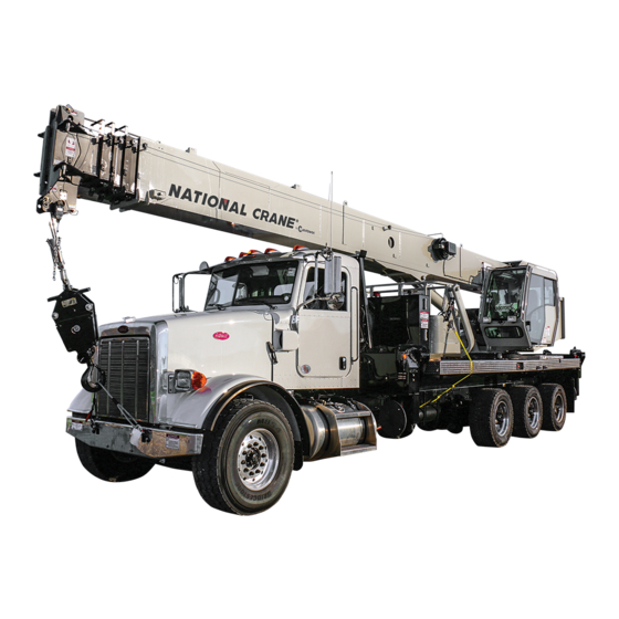
If you are the new owner of a National crane, please register performance with minimum maintenance. With proper care, it with Manitowoc Crane Care so we have the ability to years of trouble-free service can be expected. h t t p s : / / c o n t a c t y o u i f t h e n e e d a r i s e s . - Page 14 INTRODUCTION NBT40-1 SERIES OPERATOR MANUAL FIGURE 1-1 7474-2 3-29-2018 Control # 610-00...
- Page 15 NBT40-1 SERIES OPERATOR MANUAL INTRODUCTION 8839-1 7474-5 7474-4 8839-3 7474-2 Item Component Item Component Crane Cab/Cab Controls Hoist Cable, Wire Rope Crane Cab - Front Console Operator’s Seat Turret Boom Stabilizer Front Outrigger (SFO), Front Outrigger Jack Boom Nose Hydraulic Tank Boom Rest Hydraulic Pump (not shown) Lift Cylinder...
- Page 16 Care. The equipment must not be returned to service until it is thoroughly inspected for any evidence of damage. All damaged parts must be repaired or replaced as authorized by your local National Crane distributor or Manitowoc Crane Care. 3-29-2018 Control # 610-00...
-
Page 17: Section 2
NBT40-1 SERIES OPERATOR MANUAL SAFETY INFORMATION SECTION 2 SAFETY PRECAUTIONS - CRANE SECTION CONTENTS General ....... . . 2-1 Grounding the Crane . -
Page 18: Safety Alert Symbol
Should the distributor not be immediately available, contact should be made directly with Manitowoc Product Safety at the address below. The equipment must not be returned to service until it is thoroughly inspected for any evidence of damage. -
Page 19: Operator Qualifications
NBT40-1 SERIES OPERATOR MANUAL SAFETY INFORMATION each person responsible for assembly, disassembly, placards and decals on the equipment. Refer to the operation and maintenance of the equipment. Appendix, A of this Manual for the locations of safety decals. No personnel shall be allowed to climb onto the equipment or Decals provide important instructions and warnings and enter the equipment cab or operator ’s station unless must be read prior to any operational or maintenance... -
Page 20: Operational Aids
SAFETY PRECAUTIONS - CRANE NBT40-1 SERIES OPERATOR MANUAL You must be mentally and physically fi t to operate Device is inoperative or malfunctioning, the designated equipment. Never attempt to operate equipment while under person responsible for supervising the lifting operations the influence of medication, narcotics, or alcohol. -
Page 21: Working Area Limiter (If Equipped)
NBT40-1 SERIES OPERATOR MANUAL SAFETY INFORMATION the boom (boom nose, sheaves, boom extension, etc.). Two- Definition System (WADS) or Working Range Limiter (WRL). blocking can cause hoist lines (wire rope), rigging, reeving, You must read and understand the operator manual before and other components to become highly stressed and operating the working area limiter system. -
Page 22: Load Charts
SAFETY PRECAUTIONS - CRANE NBT40-1 SERIES OPERATOR MANUAL The operator must select the proper Load Chart/Reach Maximum lifting capacity is available at the shortest radius, Diagram and Rated Capacity Limiter (RCL) System program minimum boom length, and highest boom angle. for the outrigger position selected. -
Page 23: Wind Speeds
NBT40-1 SERIES OPERATOR MANUAL SAFETY INFORMATION Maximum Wind Speed Beaufort Visible Indicator Description km/h Number Effects of wind as observed on land Gentle Leaves and small twigs constantly moving. Light flags 19.4 12.1 Breeze extended. Moderate 28.4 17.7 Dust and loose paper raised. Small branches begin to move. Breeze Fresh Branches of a moderate size move. - Page 24 SAFETY PRECAUTIONS - CRANE NBT40-1 SERIES OPERATOR MANUAL Simplified Method to Determine Maximum Permissible Wind Speed Determine 3-Second Gust 0.14 V(z) = [(z/10) + 0.4]v [m/s] Wind Speed at boom tip, 0.14 V(z) = [(z/33) + 0.4]v [mph] V(z) 13.4 m/s < V(z) < 20.1 m/s V(z) >...
- Page 25 NBT40-1 SERIES OPERATOR MANUAL SAFETY INFORMATION Determination of 3-second wind gust speed at boom Size and Shape of the load: tip height: These rated capacities are also based on the assumption that the Wind Resistance Area of load, Awr is not more The following example illustrates how to calculate 3-second (load) wind gust speed at boom tip height based on mean wind...
- Page 26 SAFETY PRECAUTIONS - CRANE NBT40-1 SERIES OPERATOR MANUAL Calculation of Projected Wind Area (Ap) Wind Wind = 8 m = 24 m 25 ft 25 ft Wind Wind 10 ft 3 ft = 75 ft = 250 ft 10 ft 3 ft 8384-1 FIGURE 2-4...
- Page 27 NBT40-1 SERIES OPERATOR MANUAL SAFETY INFORMATION Table 2-2 Wind Drag Coefficient Maximum Permissible Wind Speed If the wind resistant area of the load Awr is greater than (load) Shape the allowable wind resistant area Awr , the ratio can be (allow) used to determine a permissible wind speed V(z) for the load 1.1 to 2.0...
- Page 28 SAFETY PRECAUTIONS - CRANE NBT40-1 SERIES OPERATOR MANUAL Rated Load Chart Example - Metric 8383-1 FIGURE 2-5 2-12 3-29-2018 Control # 610-00...
- Page 29 NBT40-1 SERIES OPERATOR MANUAL SAFETY INFORMATION Table 2-4 Example-Capacity Reduction Factors for Wind Speed V(z) Greater than 13.4 m/s - Metric (Only for lifting with main boom on fully extended outriggers, with or without stowed extension) For wind speed V(z) (3-second gust speed at boom tip height) V(z) > 13.4 m/s ≤ 20.1 m/s, the Reduced Capacity shall be calculated by multiplying the Published Rated Capacity by the following factors: Main Boom Length in Meters Wind Speed...
- Page 30 SAFETY PRECAUTIONS - CRANE NBT40-1 SERIES OPERATOR MANUAL At wind speeds greater than 13.4 m/s, it is not permissible to Load example 1.3a: lift a load greater than 12,040 kg, even if the wind resistance With large wind resistance area of the load Awr (load) area of the load is less than 14.45 m •...
- Page 31 NBT40-1 SERIES OPERATOR MANUAL SAFETY INFORMATION • Is the load to be lifted less than allowable load? Ratio = 1.37 8,000 kg ≤ 12,040 kg • Is Awr less than Awr (load) (allow) From Table 2-5, the maximum permissible wind speed at 19.83 m ≤...
- Page 32 SAFETY PRECAUTIONS - CRANE NBT40-1 SERIES OPERATOR MANUAL Rated Load Chart Example - Non-metric 8382-1 FIGURE 2-6 2-16 3-29-2018 Control # 610-00...
- Page 33 NBT40-1 SERIES OPERATOR MANUAL SAFETY INFORMATION Table 2-6Example-Capacity Reduction Factors for Wind Speed V(z) Greater than 30 mph - Non-metric (Only for lifting with main boom on fully extended outriggers, with or without stowed extension) For wind speed Vz (3-second gust speed at boom tip height) is greater > 30> mph ≤ 45 mph, the Reduced Capacity shall be calculated by multiplying the Published Rated Capacity by the following factors: Main Boom Length in Feet Wind Speed...
- Page 34 SAFETY PRECAUTIONS - CRANE NBT40-1 SERIES OPERATOR MANUAL • Is Awr less than Awr (load) (allow) 108 ft ≤ 119 ft L i f t i n g L i m i t s a t w i n d s p e e d V ( z ) > 3 0 m p h Conclusion: This load is permissible to lift in wind speed up and ≤...
-
Page 35: Lifting Operations
NBT40-1 SERIES OPERATOR MANUAL SAFETY INFORMATION Refer to the above Lifting Limits at wind speed V(z) Do not overload the crane by exceeding the capacities > 30 mph and ≤ 45 mph. Comparing the load and wind shown on the appropriate Load Chart. Death or serious resistant area to the allowable: injury could result from the crane tipping over or failing structurally from overload. -
Page 36: Counterweight
SAFETY PRECAUTIONS - CRANE NBT40-1 SERIES OPERATOR MANUAL COUNTERWEIGHT • Maintain communication between all parties throughout the entire operation. If possible, provide approved radio On equipment equipped with removable counterweights, equipment for voice communication between all parties ensure the appropriate counterweight sections are properly engaged in the lift. -
Page 37: Pile Driving And Extracting
NBT40-1 SERIES OPERATOR MANUAL SAFETY INFORMATION • The panel shall be lifted so that the hoist lines are in line • The pile driver and piling shall be suspended from a with the crane. hoist rope with sufficient line speed to meet or exceed the rate of descent of the driver and piling to preclude •... -
Page 38: Electrocution Hazard
SAFETY PRECAUTIONS - CRANE NBT40-1 SERIES OPERATOR MANUAL boom sections shall be inspected daily to ensure the NOTE: For detailed guidelines on operating near power pinning mechanism operates properly and to check for line s, re fer to th e c urr ent ed it io n o f OSHA undue wear at the pins and pinning plates. -
Page 39: Set-Up And Operation
NBT40-1 SERIES OPERATOR MANUAL SAFETY INFORMATION Most overhead power lines are not insulated. Treat all Appoint a reliable and qualified signal person, equipped with overhead power lines as being energized unless you have a loud signal whistle or horn and voice communication reliable information to the contrary from the utility company equipment, to warn the operator when any part of the or owner. -
Page 40: Electrical Contact
Thoroughly inspect the rope and all points of contact on the equipment. Should the distributor not be immediately • Near strong transmitters (radio transmitters, radio available, contact Manitowoc Crane Care. The equipment stations, etc.) must not be returned to service until it is thoroughly •... -
Page 41: Personnel Handling
NBT40-1 SERIES OPERATOR MANUAL SAFETY INFORMATION Hammer a metal rod (3, Figure 2-7) [length of to meet the standards for personnel handling equip- ment, such as ANSI/SAIA A92 (Aerial Services). approximately 2.0 m (6.6 ft)] at least 1.5 m (5 ft) into the The equipment and implementation requirements ground. -
Page 42: Environmental Protection
SAFETY PRECAUTIONS - CRANE NBT40-1 SERIES OPERATOR MANUAL ENVIRONMENTAL PROTECTION • The equipment is level within one percent of level grade and located on a firm footing. Equipment with outriggers Dispose of waste properly! Improperly disposing of waste shall have them all deployed following manufacturer's can threaten the environment. -
Page 43: Service And Repairs
Wear gloves to protect your hands from spraying fluid. • Consult with Manitowoc Crane Care to determine if load testing is required after a structural repair is performed. • If any hydraulic fluid is injected into the skin, obtain medical attention immediately or gangrene may result. -
Page 44: Tires
Be certain all lines, components, and fittings are tight and, therefore, require different reeving. before resuming operation. NOTE: Rope may be purchased by contacting Manitowoc Tires Crane Care. Always make daily inspections of the rope, keeping in mind that all rope will eventually deteriorate to a point where it is no longer usable. - Page 45 NBT40-1 SERIES OPERATOR MANUAL SAFETY INFORMATION • The nominal strength of a rope should be considered the Lack of lubrication can significantly shorten the straight line pull which will actually break a new unused useful life of a wire rope. rope.
-
Page 46: Sheaves
SAFETY PRECAUTIONS - CRANE NBT40-1 SERIES OPERATOR MANUAL Sheaves • If equipped, disconnect battery with the battery disconnect switch before disconnecting the ground battery cable. • Do not break a live circuit at the battery terminal. Disconnect the ground battery cable first when removing a battery and connect it last when installing a battery. -
Page 47: Travel Operation
NBT40-1 SERIES OPERATOR MANUAL SAFETY INFORMATION Do not use the dead end lug on the boom nose for tying When driving the equipment, ensure the cab is level, if down the boom during transport. Damage to the lug and equipped with a tilting cab. boom can result from usage as a tie down point. -
Page 48: Work Practices
Do not make modifications or additions to the crane’s access system that have not been evaluated and approved by Working Manitowoc Crane Care. Operator shall be responsible for all operations under his/her Do not step on surfaces on the crane that are not approved direct control. -
Page 49: Lifting
NBT40-1 SERIES OPERATOR MANUAL SAFETY INFORMATION Before actuating swing or any other crane function, sound the horn and verify that all personnel are clear of rotating and moving parts. Never operate the crane when darkness, fog, or other visibility restrictions make operation unsafe. Never operate a crane in thunderstorms or high winds. -
Page 50: Hand Signals
SAFETY PRECAUTIONS - CRANE NBT40-1 SERIES OPERATOR MANUAL Be sure the load is well secured and attached to the hook If the boom should contact an object, stop immediately and with rigging of proper size and in good condition. inspect the boom. Remove the crane from service if the boom is damaged. - Page 51 NBT40-1 SERIES OPERATOR MANUAL SAFETY INFORMATION 8496- National Crane 2-35 3-29-2018 Control # 610-00...
-
Page 52: Boom Extension
SAFETY PRECAUTIONS - CRANE NBT40-1 SERIES OPERATOR MANUAL BOOM EXTENSION that certain jobsite conditions may not permit the boom and boom extension of a crane to be fully lowered to the ground. To avoid death or serious injury, follow the procedures in this When a qualified person at a jobsite determines that it is not manual during erection, stowage, and use of the boom practical to lower the boom to the ground, we recommend... -
Page 53: Temperature Effects On Hook Blocks
NBT40-1 SERIES OPERATOR MANUAL SAFETY INFORMATION If applicable to your equipment, frequently check all air tanks The change in the length of a cylinder is proportional to the for water in freezing weather. extended length of the cylinder and to the change in temperature of the oil in the cylinder. -
Page 54: Overload Inspection
SAFETY PRECAUTIONS - CRANE NBT40-1 SERIES OPERATOR MANUAL Table 2-8: Boom Drift Chart (Cylinder length change in inches) Coeff. = 0.00043 (in / °F) STROKE Temperature Change (°F) (FT.) 0.26 0.52 0.77 1.03 1.29 1.55 1.81 2.06 2.32 2.58 0.52 1.03 1.55 2.06... - Page 55 To avoid an accident caused by overload damage to your equipment: • Perform the inspections outlined in this publication for overloads up to 50%. • Stop operating the equipment and contact Manitowoc Crane Care immediately for overloads of 50% and higher. National Crane 2-39 3-29-2018 Control # 610-00...
-
Page 56: Boom Inspection
SAFETY PRECAUTIONS - CRANE NBT40-1 SERIES OPERATOR MANUAL Boom Inspection 8836-2 9, 10 2, 3 9, 10 8836-1 Illustration for reference only. Your crane may be different. 2-40 3-29-2018 Control # 610-00... - Page 57 NBT40-1 SERIES OPERATOR MANUAL SAFETY INFORMATION NOTE: The following checklist includes all features that can be found on National Crane. Your crane may not have some features. Overload less than 25% Sheaves, Inspect all for damage. Rope Guides Collar-Wear Pads, Pad Inspect for damage.
-
Page 58: Superstructure Inspection
SAFETY PRECAUTIONS - CRANE NBT40-1 SERIES OPERATOR MANUAL Superstructure Inspection 9, 10 10,11 10,11 8836-1 Illustration for reference only. Your crane may be different. 2-42 3-29-2018 Control # 610-00... - Page 59 NBT40-1 SERIES OPERATOR MANUAL SAFETY INFORMATION NOTE: The following checklist includes all features that can be found on National Crane. Your crane may not have some features. Overload less than 25% Lift Cylinder Inspect for leaks. See topic in Introduction section Wire Rope Inspect all for damage.
-
Page 60: Carrier Inspection
SAFETY PRECAUTIONS - CRANE NBT40-1 SERIES OPERATOR MANUAL Carrier Inspection 8836-1 Illustration for reference only. Your crane may be different. 2-44 3-29-2018 Control # 610-00... - Page 61 NBT40-1 SERIES OPERATOR MANUAL SAFETY INFORMATION NOTE: The following checklist includes all features that can be found on National Crane. Your crane may not have some features. Overload less than 25% Stabilizer Inspect for leaks. Cylinders Outrigger Inspect for deformation and cracked welds. Pads Overload from 25% to 49% Stabilizer...
- Page 62 SAFETY PRECAUTIONS - CRANE NBT40-1 SERIES OPERATOR MANUAL This Page Blank 2-46 3-29-2018 Control # 610-00...
-
Page 63: Section 3
NBT40-1 SERIES OPERATOR MANUAL SAFETY INFORMATION SECTION 3 SAFETY PRECAUTIONS - AERIAL LIFT SECTION CONTENTS General ....... . . 3-1 Special Operating Conditions and Aerial Lift . -
Page 64: Signal Words
Should the distributor not be immediately available, GENERAL contact should be made directly with Manitowoc Product Safety at the address below. The aerial lift must not be It is impossible to compile a list of safety precautions returned to service until it is thoroughly inspected for any covering all situations. -
Page 65: Operator Qualifications
NBT40-1 SERIES OPERATOR MANUAL SAFETY INFORMATION and must remain in the cab (if equipped) or operator’s station Ensure that all personnel working around the aerial lift are while the aerial lift is in use. thoroughly familiar with safe operating practices. You must be thoroughly familiar with the location and content of all The Operator Manual supplied with and considered part of placards and decals on the aerial lift. -
Page 66: Operational Aids
SAFETY PRECAUTION - AERIAL LIFT NBT40-1 SERIES OPERATOR MANUAL Rated Capacity Limiter (RCL) System attempting to operate aerial lift on which you have not been trained. Your aerial lift is equipped with an RCL system which is You must be mentally and physically fit to operate an aerial intended to aid the operator. -
Page 67: Work Site
NBT40-1 SERIES OPERATOR MANUAL SAFETY INFORMATION Wind Forces Carefully follow the procedures in this Operator Manual when extending or retracting the outriggers. (“Outrigger Wind can have a significant effect on an aerial lift. (See Controls” 4-2) Death or serious injury could result from “Wind Forces”... - Page 68 SAFETY PRECAUTION - AERIAL LIFT NBT40-1 SERIES OPERATOR MANUAL Ensure a daily inspection and functional check of the aerial lift is performed prior to placing it into operation. Never operate a malfunctioning aerial lift. If a malfunction DANGER occurs, shut the aerial lift down, red tag it and notify the Aerial Lift Hazard! proper personnel of the malfunction.
-
Page 69: Boom Extension
Do not carry material or equipment on the work platform Do not add material to the counterweight to increase railing unless approved by Manitowoc Crane Care. capacity. United States Federal law prohibits modification or additions which affect the capacity or safe operation of the Never use the aerial lift for any purpose other than equipment without the manufacturer’s written approval. -
Page 70: Electrocution Hazard
SAFETY PRECAUTION - AERIAL LIFT NBT40-1 SERIES OPERATOR MANUAL ELECTROCUTION HAZARD If operation within 3 m (10 ft) of any power lines cannot be avoided, the power utility must be notified and the power Thoroughly read, understand, and abide by all applicable l i n e s m us t b e d e - e n e r g i z e d a n d g r o u n d e d bef o re federal, state, and local regulations regarding operation of performing any work. -
Page 71: Electrocution Hazard Devices
Should the distributor not be immediately available, upon you, the operator, in selecting and properly setting the contact Manitowoc Crane Care. The aerial lift must not be sensitivity of these devices. returned to service until it is thoroughly inspected for any... -
Page 72: Special Operating Conditions And Aerial Lift
SAFETY PRECAUTION - AERIAL LIFT NBT40-1 SERIES OPERATOR MANUAL Special Operating Conditions and Aerial Lift N e v e r o p e r a t e t h e a e r i a l l i f t d u r i n g a n e l e c t r i c a l thunderstorm. -
Page 73: Service And Repairs
NBT40-1 SERIES OPERATOR MANUAL SAFETY INFORMATION maintenance and lubrication are being dutifully performed. by National Crane is strictly prohibited. All replacement Never operate a damaged or poorly maintained aerial lift. parts must be National Crane approved. Such action invalidates all warranties and makes the owner/user liable National Crane recommends that aerial lift be properly for any resultant accidents. -
Page 74: Lubrication
• If equipped, disconnect battery with the battery • Consult with Manitowoc Crane Care to determine if load disconnect switch before disconnecting the ground testing is required after a structural repair is performed. battery cable. -
Page 75: Work Practices
Do not make modifications or additions to the aerial lift’s Working access system that have not been evaluated and approved by Manitowoc Crane Care. Operator shall be responsible for all operations under his/her direct control. When safety of an operation is in doubt, Do not step on surfaces on the aerial lift that are not operator shall stop the aerial lift’s functions in a controlled... - Page 76 SAFETY PRECAUTION - AERIAL LIFT NBT40-1 SERIES OPERATOR MANUAL Sparks from the aerial lift’s electrical system and/or engine Never push or pull loads with the aerial lift's boom; never exhaust can cause an explosion. Do not operate this aerial drag a load. lift in an area with flammable dust or vapors, unless good If the boom should contact an object, stop immediately and ventilation has removed the hazard.
-
Page 77: Parking And Securing
NBT40-1 SERIES OPERATOR MANUAL SAFETY INFORMATION PARKING AND SECURING • Chock the wheels, if not on outriggers. • Lock the operator’s cab (if applicable) and install vandal guards, if used. WARNING TRANSPORTING AERIAL LIFT Tipping Hazard! Before transporting the aerial lift, check the suitability of the When parking the aerial lift and leaving it unattended proposed route with regard to the aerial lift height, width, follow the instructions for the Controls and Operating... -
Page 78: Cold Weather Operation
SAFETY PRECAUTION - AERIAL LIFT NBT40-1 SERIES OPERATOR MANUAL Secure the hook block and other items before moving the Allow ample time for hydraulic oil to warm up. aerial lift. In freezing weather, park the aerial lift in an area where it Stow the outriggers and engage locking pins (if equipped). - Page 79 NBT40-1 SERIES OPERATOR MANUAL SAFETY INFORMATION This situation will also occur in reverse. If equipment is set up cylinder. The chart is for dry rod cylinders. If the cylinder rod in the morning with cool oil and the daytime ambient is filled with hydraulic oil, the contraction rate is somewhat temperature heats the oil, the cylinders will extend in similar greater.
- Page 80 SAFETY PRECAUTION - AERIAL LIFT NBT40-1 SERIES OPERATOR MANUAL This Page Blank 3-18 3-29-2018 Control # 610-00...
- Page 81 NBT40-1 SERIES OPERATOR MANUAL OPERATING CONTROLS - CRANE SECTION 4 OPERATING CONTROLS - CRANE SECTION CONTENTS Chassis Cab Controls ..... . 4-2 Seat &...
-
Page 82: Chassis Cab Controls
OPERATING CONTROLS - CRANE NBT40-1 SERIES OPERATOR MANUAL CONTROLS AND OPERATING PROCEDURES This section contains information on controls and operating operate switch DOWN to engage PTO or UP to disengage procedures to include: PTO. Return gear shift to neutral and engage clutch. •... - Page 83 NBT40-1 SERIES OPERATOR MANUAL OPERATING CONTROLS - CRANE Figure 4-1) located in the ground controls (operator control outrigger beams, for raising and lowering stabilizer (jack) station cab) and two ground station outrigger controls (2) cylinders and for raising and lowering center front stabilizer located on either side of equipment at ground level.
- Page 84 OPERATING CONTROLS - CRANE NBT40-1 SERIES OPERATOR MANUAL 7459-1 7448-15 8843 7462-14 8843 7462-22 FIGURE 4-1 3-29-2018 Control # 610-00...
- Page 85 NBT40-1 SERIES OPERATOR MANUAL OPERATING CONTROLS - CRANE Extend/retract Switch Item Description Extend/retract switch (5, Figure 4-1) is used in conjunction Hand Held Outrigger Control with the outrigger selector switches to control outrigger functions. Outrigger Control Panel Front Center Stabilizer Switch Outrigger Selector Switches Outrigger Selector Switches Outrigger selector switches (4, Figure 4-1) are used to select...
-
Page 86: Leveling Of Equipment
OPERATING CONTROLS - CRANE NBT40-1 SERIES OPERATOR MANUAL Front Center Stabilizer Switch NOTE: Center front stabilizer automatically retracts if any other components are adjusted and must be reset Center front stabilizer switch (3, Figure 4-1) is used to lower if operation is to be continued. and raise center front stabilizer. -
Page 87: Equipment Level Indicators
NBT40-1 SERIES OPERATOR MANUAL OPERATING CONTROLS - CRANE lowered to horizontal and fully retracted and stowed onto Primary level indicator (7, Figure 4-1) is located forward of boom rest. turret bearing. Secondary level indicators are located in outrigger control panels (6, Figure 4-1) and in ground control Interlock alarm will beep if crane settles outside of 1% of cab (38, Figure 4-4). - Page 88 OPERATING CONTROLS - CRANE NBT40-1 SERIES OPERATOR MANUAL 7462-6 8834-3 8834-1 FIGURE 4-3 Item Description Handheld Outrigger Control Item Description Swing Brake Pedal Auxiliary Hoist Minimum Wrap Indicator Boom Telescope Pedal (if equipped) AC/Heater Vent Foot Throttle Pedal Receptacle (12V) RCL Display Panel Radio Remote /Aerial Power Switch (if equipped) RCL Bypass Switch (Momentary)
-
Page 89: Swing Brake Pedal
NBT40-1 SERIES OPERATOR MANUAL OPERATING CONTROLS - CRANE 7462-4 7462-5b FIGURE 4-4 Item Description Item Description Boom Lift Control Lever Seat Slide Handle Hoist Up & Down Control (Rotation Indicator) Seat Frame Slide Handle Telescope Boom (Auxiliary Hoist Control) Climate Control Unit Warning Horn Button Level Turret Swing Control Lever... -
Page 90: Rcl And Minimum Wrap Bypass Switch
OPERATING CONTROLS - CRANE NBT40-1 SERIES OPERATOR MANUAL DANGER RCL only aids operator when properly programmed with proper Load Chart/Reach Diagram and crane configuration. To prevent injury or death to personnel, be sure RCL is programmed before crane operation. RCL and Minimum Wrap Bypass Switch RCL bypass switch (6, Figure 4-3) is a momentary on-off switch, turn key to the On position (right) to disengage RCL controls and minimum wrap lockout controls. -
Page 91: Emergency Stop Switch
NBT40-1 SERIES OPERATOR MANUAL OPERATING CONTROLS - CRANE Releasing button (1) will lock knob in place and maintain When amount of rope left on hoist reaches minimum wrap; engine speed. indicator light will be constant, buzzer will be constant and hoist will be disabled by minimum wrap sensor system. -
Page 92: Windshield Wiper Switch
OPERATING CONTROLS - CRANE NBT40-1 SERIES OPERATOR MANUAL Windshield Wiper Switch Windshield wiper switch (24, Figure 4-3) is located in overhead console. This is Hi - Lo toggle type switch with 6 intermittent positions, (intermittent timing is 2-15 seconds, wiper washer timing is 3 seconds). Cab Climate Controls Cab climate controls (25, 26, 27, Figure 4-3) are used to adjust heating and air conditioning for operator comfort. -
Page 93: Swing Control Lever
NBT40-1 SERIES OPERATOR MANUAL OPERATING CONTROLS - CRANE Swing Control Lever House Lock House lock control (40, Figure 3-3) is a manually operated CAUTION mechanical lock that when engaged prevents rotation of crane superstructure. Do not actuate Swing Control Lever while Swing Brake is engaged, as turret may push through brake. -
Page 94: Adjustable Swing Speed Valve
OPERATING CONTROLS - CRANE NBT40-1 SERIES OPERATOR MANUAL OPERATING PROCEDURES You need to be familiar with the safety precautions outlined in this manual before operating the crane. Crane Familiarization All members of crew should become familiar with location and operation of controls, correct operating procedure, the maximum lifting capacities, and Safety Precautions Section of this manual. -
Page 95: Cold Weather Operation
Lubrication section of your equipment’s Operator Manual, by contacting your local • damaged structural members and welds. National Crane distributor, or by contacting Manitowoc • all rope guides and cable keepers. Crane Care directly). -
Page 96: Swing Drive And Turntable Bearing
SAE J159. If there is any unusual sound coming from crane’s hydraulic pumps or motors, stop operation and engine immediately and contact a Manitowoc distributor. DANGER • From 10°C to 4°C (50°F to 40°F): Crane operation with... -
Page 97: Outrigger Setup
NBT40-1 SERIES OPERATOR MANUAL OPERATING CONTROLS - CRANE OUTRIGGER SETUP CAUTION Possible Equipment Damage! DANGER Always depress one of the outrigger selector switches Do not operate outriggers unless they are visible to either before positioning outrigger extend/retract switch to operator or a designated signal person to avoid crushing extend or retract. -
Page 98: Outrigger Monitoring System (Oms)
OPERATING CONTROLS - CRANE NBT40-1 SERIES OPERATOR MANUAL indicator is out of adjustment, verify and adjust bubble configuration). A confirmation of this configuration is all that level using procedures under Equipment Level is needed (see Figure 4-14). Refer to Rated Capacity Limiter Indicators Adjustment, page 4-17. -
Page 99: Startup
NBT40-1 SERIES OPERATOR MANUAL OPERATING CONTROLS - CRANE This system is comprised of several sensors and modules Boom angle sensor located internal to the RCL system located throughout the machine: length and angle cable reel on left side of boom. Outrigger string potentiometers are used in the standard Startup outrigger monitoring system (OMS). -
Page 100: Hoist System Operation
OPERATING CONTROLS - CRANE NBT40-1 SERIES OPERATOR MANUAL WORK SITE LOCATION sounds. Operator must immediately retract and lower boom and place the boom in the boom rest and relevel the crane. Select a location that is firm, level, and dry. Avoid uneven, rocky or muddy terrain, steep grade or locations with HOIST SYSTEM OPERATION overhead obstructions. -
Page 101: Unattended Equipment
NBT40-1 SERIES OPERATOR MANUAL OPERATING CONTROLS - CRANE Make crane as stable as possible, including, boom angle, superstructure orientation, jib angle, etc. In high winds, boom and jibs should be lowered or DANGER secured. Tipping Hazard! b. Engage swing brake and/or swing lock pin. Serious injury or death could result from improper crane Apply parking brake. - Page 102 OPERATING CONTROLS - CRANE NBT40-1 SERIES OPERATOR MANUAL boom extension, and fully retracted outrigger beams for main The load chart contains crane lifting capacities in all boom only. allowable lifting configurations and must be thoroughly understood by the operator. Prior to any fully retracted outrigger (0% extended) operation, extend jack cylinders with outriggers fully The left column is the load radius, which is the distance from retracted and level crane.
-
Page 103: Lifting The Load
NBT40-1 SERIES OPERATOR MANUAL OPERATING CONTROLS - CRANE A lifting diagram is included for over-side, over-rear, and Retract and lower boom after lift is complete. over-front lifting areas. The lifting area diagram shows locations of the outrigger jack cylinders in full extended SHUT DOWN AND PREPARATION FOR position are used to mark lifting area boundaries. - Page 104 OPERATING CONTROLS - CRANE NBT40-1 SERIES OPERATOR MANUAL Slowly hoist up until there is a slight tension on hoist rope. It may be necessary to override A2B function to tension rope. b. A2B weight needs to be resting on wedge socket so that there is slack in anti-two-block-chain.
-
Page 105: Section 5
NBT40-1 SERIES OPERATOR MANUAL OPERATING CONTROLS - AERIAL LIFT SECTION 5 OPERATING CONTROLS - AERIAL LIFT SECTION CONTENTS Controls And Operating Procedures ..5-1 RCL Check ......5-14 Aerial Lift Controls . -
Page 106: Power Take Off
OPERATING CONTROLS - AERIAL LIFT NBT40-1 SERIES OPERATOR MANUAL Power Take Off A working aerial lift may settle during operations. Frequently check the aerial lift for level. When rechecking the aerial lift The power take off (PTO) must be engaged for aerial lift for level, the boom must be positioned over the front of the operations. -
Page 107: Platform Controls
NBT40-1 SERIES OPERATOR MANUAL OPERATING CONTROLS - AERIAL LIFT Do not operate aerial lift from the ground controls without Position equipment at job site, set park brake, and shift permission of the work platform occupant(s) except in the transmission to neutral. case of emergency such as a disabled operator. - Page 108 OPERATING CONTROLS - AERIAL LIFT NBT40-1 SERIES OPERATOR MANUAL FIGURE 5-3 8844-1 Radio Remote Transmitter Operation Item Symbol/Icon Function Logic Type Proportional Swing Clockwise Joystick Swing Proportional Counterclockwise Joystick Proportional Telescope Extend Joystick 3-29-2018 Control # 610-00...
- Page 109 NBT40-1 SERIES OPERATOR MANUAL OPERATING CONTROLS - AERIAL LIFT Radio Remote Transmitter Operation Item Symbol/Icon Function Logic Type Proportional Telescope Retract Joystick Proportional Default is to OFF upon remote initialization Auxiliary Hoist Up Joystick in aerial mode. Proportional Default is to OFF upon remote initialization Auxiliary Hoist Down Joystick in aerial mode.
- Page 110 OPERATING CONTROLS - AERIAL LIFT NBT40-1 SERIES OPERATOR MANUAL Radio Remote Transmitter Operation Item Symbol/Icon Function Logic Type Latching Default is OFF upon remote initialization in Main Hoist Enable button aerial mode. Latching Default is OFF upon remote initialization in Main Hoist High Speed button aerial mode.
-
Page 111: Aerial Functions
NBT40-1 SERIES OPERATOR MANUAL OPERATING CONTROLS - AERIAL LIFT Radio Remote Transmitter Operation Item Symbol/Icon Function Logic Type 3-position latching Speed Selection toggle switch (100%/50%/Low Flow) Default is OFF when remote is enabled 2-position, even if this switch is in the ON position. Tool Circuit latching toggle switch... -
Page 112: Emergency Lowering Procedure
OPERATING CONTROLS - AERIAL LIFT NBT40-1 SERIES OPERATOR MANUAL The momentary HORN/ENABLE button (Item 13) must This system will be activated for a maximum of 2 be depressed. minutes allowing operation at reduced speeds until timeout. The emergency lowering switch can be turned Depress the ENGINE START button (Item 14) to start OFF by pressing the AUX PUMP switch again. -
Page 113: Operational Procedure
NBT40-1 SERIES OPERATOR MANUAL OPERATING CONTROLS - AERIAL LIFT has elapsed and the AUX PUMP icon on the Radio set park brake, shift transmission to neutral, and turn Remote Transmitter’s display stops flashing. OFF truck engine. Start engine from lower control station (operators cab). Set outriggers and level the equipment. - Page 114 OPERATING CONTROLS - AERIAL LIFT NBT40-1 SERIES OPERATOR MANUAL DANGER Fall Hazard! Working at elevated heights without using proper fall protection can result in severe injury or death. Always use proper fall protection as required by local, state or federal regulations. Open gate and enter personnel platform and attach safety harness per operator manual instructions.
-
Page 115: Operator Presence Footswitch
NBT40-1 SERIES OPERATOR MANUAL OPERATING CONTROLS - AERIAL LIFT Stow jib, unstow loadline(s) and reeve hookblock(s) and If a platform function is not activated within 10 seconds, the A2B weight(s) as needed. platform controls are deactivated. The operator must step off the operator presence footswitch, then depress it again to Stow aerial lift platform and place boom in boomrest. - Page 116 OPERATING CONTROLS - AERIAL LIFT NBT40-1 SERIES OPERATOR MANUAL Operator Feedback Screen Item Symbol/Icon Function Description Real-time display of the rechargable battery. Figure 5-9 Battery indicator Audible alarm on the platform controls will indicate when critically low battery level. Signal strength of the wireless communication Figure 5-9 Signal strength between the wireless receiver and the...
-
Page 117: Rcl Display
NBT40-1 SERIES OPERATOR MANUAL OPERATING CONTROLS - AERIAL LIFT FIGURE 5-10 RCL Information Screen Example (Radius) Item Symbol/Icon Function Description Actual percent of max useable platform reach being used (%). Aerial Reach Utilization Actual radius (feet) from centerline of rotation Radius to the center of the boom nose lower sheaves. -
Page 118: Rcl Check
OPERATING CONTROLS - AERIAL LIFT NBT40-1 SERIES OPERATOR MANUAL high pressure source and allows return oil to bypass the hydraulic intensifier and return to tank line. Reference DANGER 9828221048 Valve Intensifier manual. The RCL aids the operator when properly programmed Hose Installation with the proper equipment configuration. -
Page 119: Equipment Familiarization
NBT40-1 SERIES OPERATOR MANUAL OPERATING CONTROLS - AERIAL LIFT Equipment Familiarization • Check the work area for electric power lines. All members of the crew should become familiar with the location and operation of the controls, the correct operating DANGER procedure, the maximum working range, and the Safety Chassis must be in neutral when starting engine from Precautions in manual. -
Page 120: Function Check
OPERATING CONTROLS - AERIAL LIFT NBT40-1 SERIES OPERATOR MANUAL Aerial Lift Platform Attachment Structure who possess the skill, experience, and dexterity to ensure smooth operation. Shock loading shall be avoided. • no loose or missing parts. NOTE: Aerial Lift operation below -29°C (-20°F) is not •... -
Page 121: Unattended Equipment
NBT40-1 SERIES OPERATOR MANUAL OPERATING CONTROLS - AERIAL LIFT Put all operating controls in the neutral position. If the jib is stowed on the side of boom, caution must be taken to avoid contact between the platform mounting Position the Radio Remote/Aerial Power Switch (19) bracket and the jib attaching pin holes. -
Page 122: Shut Down And Preparation For Road Travel
OPERATING CONTROLS - AERIAL LIFT NBT40-1 SERIES OPERATOR MANUAL SHUT DOWN AND PREPARATION FOR Retract and place the boom in boom rest. ROAD TRAVEL Ensure the center front stabilizer is fully retracted, if equipped. Ensure the outrigger beams and jacks are fully retracted CAUTION and secured with the floats properly stowed. -
Page 123: Jib Safety Information
NBT40-1 SERIES OPERATOR MANUAL SET-UP SECTION 6 EQUIPMENT SET-UP SECTION CONTENTS Jib Safety Information ..... . 6-1 Hoist Rope Tie Down......6-9 Hoist Rope Tie Down - Boom Mounted Hoist . -
Page 124: Jib Operation
SET-UP NBT40-1 SERIES OPERATOR MANUAL JIB OPERATION pin B, are removed and swing pins (C1) are in place. Jib could swing uncontrollably if boom is not horizontal. Deployment Procedure Equipment shall be fully set up according to proper set- up procedures outlined previously when stowing or Using boom telescope function, fully retract boom. -
Page 125: Stowing Procedure
NBT40-1 SERIES OPERATOR MANUAL SET-UP 19. For manually extendable jibs, pull extension retaining pin (E, Figure 6-1), and extend second section out by pulling on sheave case. The second section jib, as it extends, will hit a mechanical stop that allows for extension pin (E) installation. - Page 126 SET-UP NBT40-1 SERIES OPERATOR MANUAL JIb in Operating position 7462-27 Stow Pin Jib Swing Pin Jib Deployment Pins Hook Bracket Extension Retaining Pin Jib in Stow Position Jib Jack Jack Handle Jib Stowage Bracket Left Side Right Side 7462-28 FIGURE 6-1 3-29-2018 Control # 610-00...
-
Page 127: Jib Removal
NBT40-1 SERIES OPERATOR MANUAL SET-UP Two section jib - Install extension retaining pin (E, 14. Using boom telescope function, slowly retract boom. Figure 6-1 through the 1 and 2 section jib assembly The jib stow bracket (H, Figure 6-1) on the side of the jib and install spring clip. -
Page 128: Rope Installation-Hoist
(3) the top of the wedge with a mallet. Synthetic Rope For detailed information concerning synthetic hoist rope, refer to K100™ Synthetic Crane Hoist Line Manual P/N 9828100734 available by contacting Manitowoc Crane Care. Wire Rope NOTE: The wire rope should preferably be straightened... -
Page 129: Wedge Sockets
NBT40-1 SERIES OPERATOR MANUAL SET-UP WEDGE SOCKETS To attach a terminator wedge, use the following procedure: Match the socket, wedge, and clip to the wire rope and To install a wedge socket: size the rope with the go and no go hole in the socket. •... -
Page 130: Dead-End Rigging
SET-UP NBT40-1 SERIES OPERATOR MANUAL will wear into the rope causing damage to the rope and Of the methods shown below, Manitowoc prefers that eventual failure. method A or F be used, i.e., clipping a short piece of wire rope to the dead-end or using a commercially available specialty wedge. -
Page 131: Hoist Rope Tie Down
NBT40-1 SERIES OPERATOR MANUAL SET-UP Hoist Loadline Tie Down Specialty Clip Specialty Wedge Wedge Socket FIGURE 6-6 HOIST ROPE TIE DOWN boom nose until the wedge socket (3) has cleared the boom nose. Hoist Rope Tie Down - Boom Mounted Hoist NOTE: A single reeved hook block (4) is shown, your machine may be reeved differently. - Page 132 SET-UP NBT40-1 SERIES OPERATOR MANUAL 8850-9 7171-1 7171-2 FIGURE 6-7 6-10 3-29-2018 Control # 610-00...
-
Page 133: Stow Pegs For Hoist Rope
For detailed information concerning synthetic hoist rope, STOWAGE refer to K100™ Synthetic Crane Hoist Line Manual P/N 9828100734 available by contacting Manitowoc Crane Care. To prevent the hoist rope from slipping out of the A2B weight, rig the weight as shown in Figure 6-9. -
Page 134: Aerial Lift Platform
SET-UP NBT40-1 SERIES OPERATOR MANUAL AERIAL LIFT PLATFORM The platform is equipped with a manually applied brake to keep platform from swinging when the platform is being An Aerial Lift Platform is available for National Cranes. The loaded or after the desired work position is reached. The platform can be attached to either the tip of the boom or the brake is intended to be disengaged when the platform is tip of the jib for the purpose of lifting personnel and their work... - Page 135 NBT40-1 SERIES OPERATOR MANUAL SET-UP 8850-5a I l l u s t r a t i o n s m a y a p p e a r slightly different than on crane 8850-3a FIGURE 6-10 National Crane 6-13 3-29-2018 Control # 610-00...
-
Page 136: Aerial Lift Platform Installation
SET-UP NBT40-1 SERIES OPERATOR MANUAL Item No. Description Item No. Description A2B Weight Platform A2b Weight and Chain Yoke Operation Chart Adapter Float Selector Attaching Pin Brake Selector Gate Hand Pump Gate Latch Manual Holder Leveling Cylinder Safety Harness Anchor Leveling Valve Quick Disconnect Grease Fitting... -
Page 137: Platform Quick Attachment
NBT40-1 SERIES OPERATOR MANUAL SET-UP Anchor Peg Hoist Rope Hoist Rope Loadline Link Slot in A2B Weight The chain must be between the cable and the slot in the weight. FIGURE 6-12 Platform Quick Attachment Extend boom in order to dis-engage boom from jib attaching point. - Page 138 SET-UP NBT40-1 SERIES OPERATOR MANUAL Platform Attachment - Boom and Jib Jib Attachment Note: Platform is removed for clarity 9215-9 Attaching pins and clips Main Boom Attachment 9215-8a Secure the attachment hardware with the pins and clips. 9215-1a FIGURE 6-13 6-16 3-29-2018 Control # 610-00...
-
Page 139: Platform Mounting And Installation
NBT40-1 SERIES OPERATOR MANUAL SET-UP 7126-1 FIGURE 6-14 Platform Mounting and Installation Connect the safety harness to the anchor point. Close The following operating instructions explain how to raise the the platform gate (3, Figure 6-14) by lifting up on the platform assembly to the level necessary to attach the gate grab handle (2) and move the gate to the closed platform adapter to the boom nose. -
Page 140: Hydraulic Tool Connection - Optional
SET-UP NBT40-1 SERIES OPERATOR MANUAL After the platform is raised to the working position; rotate the brake selector (2, Figure 6-15) (counterclockwise) position to lock the brake. This locks the yoke assembly into position and prevents free-swing when the platform is attached to the boom nose or jib tip. -
Page 141: Section 7
In areas of extreme conditions, the can threaten the environment. service periods and lubrication specifications should be Potentially harmful waste used in Manitowoc equipment altered to meet existing conditions. For information on includes — but is not limited to — oil, fuel, grease, coolant,... -
Page 142: Arctic Conditions Below -9°C (15°F)
If you are in doubt about the -7°C (+20°F) suitability of a specific fluid, check with your authorized +5°C (+40°F) National Cranes distributor or Manitowoc Crane Care. +10°C (+50°F) NOTE: All fluids and lubricants may be purchased by contacting the Manitowoc Crane Care Parts Open Gear Lubricant Department. -
Page 143: Standard Hydraulic Oil
Temperature Down to -9°C (15°F) to -29°C (-20°F) level and must meet John Deere Standard JDM J20C. Contact your National Crane distributor or Manitowoc Crane For colder operating conditions, the standard fluid may be Care if you have any questions. - Page 144 Actual intervals should be formulated by the operator to Chart (Figure 7-3). Lube description and symbols are found correspond accordingly to conditions such as continuous in tables below. duty cycles and/or hazardous environments. Table 7-1 Manitowoc Lube Specification Symbol Description Cold Weather - Standard 40°C (-40°F)
- Page 145 NBT40-1 SERIES OPERATOR MANUAL LUBRICATION Lubrication Points Grease Tube 7471-1 FIGURE 7-1 Table 7-2 Recommended Item Application Procedure Frequency Lubricant Weekly As Required Semi- Hydraulic oil reservoir Hydraulic Oil Check fill change Annually After first 40 Hrs. As indicated by Oil filter, Hydraulic oil reservoir Change or clean gauge thereafter.
- Page 146 LUBRICATION NBT40-1 SERIES OPERATOR MANUAL Recommended Item Application Procedure Frequency Lubricant Turntable bearing EP-MPG Grease gun Weekly Chassis Grease Change After First 100 Operating Hours Pump Drive U-Joint - 2 ea. (If Equipped) Check and Fill Change Weekly Coupling Lube Semi-Annually Pump Spline Shaft (Direct Mount) Spline Lubricant...
-
Page 147: Boom Lubrication
NBT40-1 SERIES OPERATOR MANUAL LUBRICATION BOOM LUBRICATION Remove access plate at top rear of the base section. Extend the boom until wear pads are centered in access Internal Cable Sheave Lubrication opening and apply grease to all wear pads and contact surfaces at the top of all boom sections with a grease gun or a brush. -
Page 148: Hoist Brake Oil
LUBRICATION NBT40-1 SERIES OPERATOR MANUAL Hoist Brake Oil DANGER Do not, under any circumstances, work at an elevated height without using proper fall protection as required by local, state or federal regulations. Check Hoist Brake Oil To check the hoist brake oil, remove the inspection plug (2, Figure 7-3) and visually inspect the oil level. -
Page 149: Swing Gearbox And Brake Oil
-23° C to 82° C (-10° F to +180° F). For • Install the vent plug (3) operation outside this range, contact Manitowoc Crane Care Hoist gear lubricants are satisfactory for operation in for recommendations. temperatures from -23° C to 66° C (-10° F to +150° F). For operation outside this range, contact Manitowoc Crane Care for recommendations. -
Page 150: Air Conditioning
LUBRICATION NBT40-1 SERIES OPERATOR MANUAL The object of rope lubrication is to reduce internal friction and to prevent corrosion. The type and amount of lubrication applied during manufacture depends on the rope size, type, and anticipated use. This lubrication provides the finished rope with protection for a reasonable time if the rope is stored under proper conditions. -
Page 151: Aerial Lift Platform Lubrication
NBT40-1 SERIES OPERATOR MANUAL LUBRICATION AERIAL LIFT PLATFORM LUBRICATION Aerial Lift Platform moving components are lubricated during manufacture. The only lubrication points required are the leveling cylinder grease fittings requiring EP-MPG grease monthly or as required (See Figure 7-8). Grease Fitting FIGURE 7-8 8850-6... -
Page 152: Carwell® Rust Inhibitor
While the surfaces of the crane that are easily seen have the biggest impact on the appearance of the crane, particular Manitowoc Crane Group's cranes are manufactured to high attention should be given to the undercarriage of the crane to quality standards, including the type of paint finish minimize the harmful effects of corrosion. -
Page 153: Inspection And Repair
• Prepare the surface prior to applying the finish coat of paint. Please contact Manitowoc Crane Care should you have any questions. National Crane 7-13 3-29-2018 Control # 610-00... -
Page 154: Areas Of Application
LUBRICATION NBT40-1 SERIES OPERATOR MANUAL Areas of Application • Superstructure applications are; hose end and fittings, wire rope on hoist roller tensioning springs on hoists, all Refer to Figure 7-9 unpainted fasteners and hardware, valves, slew ring fasteners and all bare metal surfaces. •... - Page 155 NBT40-1 SERIES OPERATOR MANUAL LUBRICATION 8839-5 8839-4 FIGURE 7-9 National Crane 7-15 3-29-2018 Control # 610-00...
- Page 156 LUBRICATION NBT40-1 SERIES OPERATOR MANUAL Item Description Headache Ball/Hook block Item Description O/R Pins, Clips Hoist Plumbing Connections Mirror Mounting Hardware Tension Spring Powertrain Hardware Counterweight Pins O/R Hose Connections All Hardware, Clips, Pins, Hose Connections not painted O/R Pins, Clips Entire underside of unit Valvebank, Hose Connections inside turntable Turntable Bearing Fasteners...
-
Page 157: Inspection And Maintenance
An inspection log book is Do not, under any circumstances, work at an elevated available from your National Crane distributor or height without using proper fall protection as required by Manitowoc Crane Care. local, state or federal regulations General Inspections WARNING... - Page 158 MAINTENANCE CHECKLIST NBT40-1 SERIES OPERATOR MANUAL Radiator coolant level. Battery water level. Loose parts or damage to structures or welds. Tire pressure. Operation of lights, safety equipment and gauges. Lubrication as specified by the Lubrication, Section 7. Condition of tires and suspension. Inspect the T-box mounting bolts during the first month of operation and periodic inspections thereafter.
-
Page 159: Special Boom Inspection
For detailed information concerning synthetic hoist rope, full range. refer to K100™ Synthetic Crane Hoist Line Manual P/N 9828100734 available by contacting Manitowoc Crane Care. Hydraulic systems for proper operating pressure. During installation and setup, care must be taken to avoid Outrigger pads for excessive wear or cracks. -
Page 160: Dynamic Shock Loads
MAINTENANCE CHECKLIST NBT40-1 SERIES OPERATOR MANUAL preventing premature wear and to insure long-term • Loss of rope diameter in a short rope length or satisfactory performance. unevenness of outer strands indicates the rope needs to be replaced. NOTE: Refer to Wire Rope Lubrication, page 7-10 for wire rope lubrication requirements. -
Page 161: Wire Rope Replacement
NBT40-1 SERIES OPERATOR MANUAL MAINTENANCE CHECKLIST Sections in contact with saddles, equalizer sheaves, • Evidence of heat damage. or other sheaves where rope travel is limited. • Reductions from nominal diameter of more than: Sections of rope at or near terminal ends where 0.0156 in (.4 mm) for rope diameters to 0.313 in (8 corroded or broken wires may protrude. -
Page 162: Equipment Adjustments And Repairs
Check the ram every three months for any sign of rust or system, the replacement cable must be obtained through the corrosion. Clean as needed and wipe with an oil saturated Manitowoc Crane Care. Extension cables are pre-stretched cloth. and have special connections for proper operation. - Page 163 NBT40-1 SERIES OPERATOR MANUAL MAINTENANCE CHECKLIST Condition Possible Cause Possible Solution Insure the RCL system is working properly and RCL system inoperative. the anti-two-block solenoid is powered. Load too heavy. Check load chart. PTO not engaged. Engage PTO. Low hydraulic fluid supply. Check and fill as required.
- Page 164 MAINTENANCE CHECKLIST NBT40-1 SERIES OPERATOR MANUAL Condition Possible Cause Possible Solution Turn circuit relief valves sticking. Clean and check circuit pressure. Turntable bearing drag. Lubricate thoroughly as rotating boom. Swing will not turn Check brake pilot pressure. Clean pilot line or Brake not releasing properly.
- Page 165 NBT40-1 SERIES OPERATOR MANUAL MAINTENANCE CHECKLIST Condition Possible Cause Possible Solution Check fuse at equipment cab console. Replace Blown fuse. System is in a state of if necessary. constant cut-out. ATB switch open. Ensure that ATB switch is closed. System cuts out too early or RCL programmed wrong.
- Page 166 MAINTENANCE CHECKLIST NBT40-1 SERIES OPERATOR MANUAL This Page Blank 8-10 3-29-2018 Control # 610-00...
-
Page 167: Inspection And Maintenance
10 of this National Cranes and Aerial Lifts Operator distributor and/or Manitowoc Crane Care. Manual and Service Manuals. Since Manitowoc has no direct control over field Inspection requirements for owners and operators of inspection, testing and maintenance, safety while... -
Page 168: Pre-Start Or Frequent Inspections
National Crane distributor or Manitowoc Crane Care. Pre-Start Functional Test Functional test of all systems and functions of the aerial WARNING... - Page 169 NBT40-1 SERIES OPERATOR MANUAL MAINTENANCE CHECKLIST Loose parts or damage to structures or welds. Control and drive mechanisms for excessive wear and/ or contamination from lubricants, water or other foreign Operation safety equipment. matter. Lubrication as specified by the Lubrication, Section 7. Weekly Inspections Evidence of oil leaks from hoses.
- Page 170 MAINTENANCE CHECKLIST NBT40-1 SERIES OPERATOR MANUAL This Page Blank 3-29-2018 Control # 610-00...
-
Page 171: Section 10
NBT40-1 SERIES OPERATOR MANUAL MAINTENANCE CHECKLIST SECTION 10 SPECIFICATIONS SECTION CONTENTS Tire Load And Inflation Table ....10-3 Hoist System ......10-6 Specifications . - Page 172 MAINTENANCE CHECKLIST NBT40-1 SERIES OPERATOR MANUAL Dimensional Drawing R2622 Counterweight Tail Swing 8839-2 R1919 Cab Swing TYPICAL VIEW ONLY 10431 (Ret-142’ Boom) 9512 (Ret-103’ Boom) 9520 (Ret-127’Boom) 11707 (Ret-161’ Boom) 43188 (Ext-142’ Boom) 31395 (Ext-103’ Boom) 38697 (Ext-127’Boom) 48970 (Ext-161’ Boom) 9647 (142’...
-
Page 173: Tire Load And Inflation Table
NBT40-1 SERIES OPERATOR MANUAL MAINTENANCE CHECKLIST TIRE LOAD AND INFLATION TABLE NOTE: The values in the tables below are as published by the Tire and Rim Association 2005. Your vehicle Definite tire inflation pressures are established for each tire may be equipped with other tire sized or the same size depending upon the load imposed on the tires. - Page 174 MAINTENANCE CHECKLIST NBT40-1 SERIES OPERATOR MANUAL Radial Ply Metric Tires for Trucks, Busses, and Trailers Used in Normal Highway Service Radial Ply Tires Mounted on 15° Drop Center Rims Tire and Rim Association Standard Radial Ply Metric Tires for Trucks, Busses, and Trailers Used in Normal Highway Service Radial Ply Tires Mounted on 15°...
- Page 175 NBT40-1 SERIES OPERATOR MANUAL MAINTENANCE CHECKLIST Metric Wide Base Tires for Trucks, Busses, and Trailers Used in Normal Highway Service Tires Used as Singles Mounted on 15° Drop Center Rims Tire and Rim Association Standard Radial Ply Tires for Trucks, Busses, and Trailers Used in Normal Highway Service Radial Ply Tires Mounted on 15°...
-
Page 176: Specifications
MAINTENANCE CHECKLIST NBT40-1 SERIES OPERATOR MANUAL SPECIFICATIONS PTO Minimum Torque Rating ..........644 Nm (475 lb-ft) PTO Minimum Horsepower Rating........67 kW (90 hp) per 1,000 rpm of PTO shaft speed 148 KW (199hp) per 2,200 rpm of PTO shaft speed Hydraulic Hydraulic Pump .............. -
Page 177: Equipment Operating Speeds
NBT40-1 SERIES OPERATOR MANUAL MAINTENANCE CHECKLIST Nominal Breaking Strength ..........25,582 kg (56,400 lb) Operating Pressure ..............303.4 +/- 6.9 bar (4,400 +/-100 psi) Flow ..................132.4 lpm (35 gpm) Hoist Line Pull/Layer Layer Low Speed kN (lb) High Speed kN (lb) 66.7 (15,000) 33.4 (7,516) 60.2 (13,529) 30.1 (6,765) -
Page 178: General
MAINTENANCE CHECKLIST NBT40-1 SERIES OPERATOR MANUAL General NBT36-1................32.6 metric tons (36 tons) at 2.13 m (7 ft) radius NBT40-1................36.3 metric tons (40 tons) at 2.13 m (7 ft) radius NBT45-1................40.8 metric tons (45 tons) at 2.13 m (7 ft) radius *NBT36-1 103ft. - Page 179 The hook block must be sized to the number of line parts. For example, do not use a six part line hook block on a three part line reeving. Contact your National Crane Distributor or Manitowoc Crane Care to order the proper hook block.
- Page 180 MAINTENANCE CHECKLIST NBT40-1 SERIES OPERATOR MANUAL This Page Blank 10-10 3-29-2018 Control # 610-00...
-
Page 181: Section 11
It is the user’s responsibility to follow manufacturer ’s • Signs and labels are available from Manitowoc instructions on machine operation, application, and observe CraneCare (see Spare parts catalog). pertinent laws and regulations and capacity charts before operating machine. - Page 182 SAFETY DECALS NBT40-1 SERIES OPERATOR MANUAL Warnings and Information Signs 8887-1 FIGURE 11-1 11-2 3-29-2018 Control # 610-00...
- Page 183 NBT40-1 SERIES OPERATOR MANUAL SAFETY DECALS 8887-2 FIGURE 11-1 National Crane 11-3 3-29-2018 Control # 610-00...
- Page 184 SAFETY DECALS NBT40-1 SERIES OPERATOR MANUAL Item Description Item Description Decal-Danger Backup Alarm Decal-Danger Electrocution Decal-Supporting Chain Decal-Danger-Hoisting Personnel Decal-Danger Loadline Decal-Hand Signal Decal-Safety Harness Decal-Danger-Crushing Decal-Caution-No Pin Decal Caution-Powerwash Decal-Danger A2B Override Decal-Caution Decal-Boom Extension Fall Decal-Danger S/S Crush Decal-Boom Extension Pin Stowage Decal-Danger Outrigger Crush Decal-Boom Extension Crushing...
- Page 185 NBT40-1 SERIES OPERATOR MANUAL SAFETY DECALS Decal Explanation of Decal Item Hand Signals for Controlling Crane Operations DANGER Crushing Hazard Contact with moving outriggers can result in Death or Serious Injury. Keep Clear of Outriggers. CAUTION Do not power wash this unit with High Pressure Spray. Electronic equipment will be damaged.
- Page 186 SAFETY DECALS NBT40-1 SERIES OPERATOR MANUAL Decal Explanation of Decal Item CAUTION Towing of crane by attaching front outrigger may result in structural damage. DANGER Swinging upper structure will cause Death or Serious Injury. Keep clear of upper structure. DANGER Crushing Hazard Contact with a moving outriggers will cause Serious Crushing Injury.
- Page 187 NBT40-1 SERIES OPERATOR MANUAL SAFETY DECALS Decal Explanation of Decal Item DANGER Failure to maintain the backup alarm will result in Death or Serious Injury. This vehicle is equipped with a backup alarm. • Alarm must sound when backing. • It is the driver’s responsibility to operate this vehicle in a safe manner and keep alarm in operable condition.
- Page 188 SAFETY DECALS NBT40-1 SERIES OPERATOR MANUAL Decal Explanation of Decal Item DANGER Two Blocking the loadline will result in Death or Serious Injury • Do not two block the loadline by contacting the sheave head with the downhaul weight. • When using the aerial work platform, the loadline must be stowed and the anti-two-block override flag must be placed in the override position.
- Page 189 NBT40-1 SERIES OPERATOR MANUAL SAFETY DECALS 8888-1 8888-2 FIGURE 11-2 National Crane 11-9 3-29-2018 Control # 610-00...
- Page 190 SAFETY DECALS NBT40-1 SERIES OPERATOR MANUAL Item Description Item Description Decal-Caution Stabilizer-Front Decal-Warning California Proposition 65 Decal-Electrocution Decal-Danger S/S Swing Crush Decal-Danger A2B Decal-Danger Tip Over Hazard Decal-Danger Tipping Decal-Danger-A2B Override Decal-Caution- Boom Attach Decal-Danger-O/R Crush Decal-Danger LMI Override Decal-Caution Armrest Position Decal-Danger Swing S/S Decal-Danger Operator Decal...
- Page 191 NBT40-1 SERIES OPERATOR MANUAL SAFETY DECALS Decal Explanation of Decal Item DANGER Tip - Over Hazard. Overturning of equipment will cause Death or Serious Injury. Read and understand operator’s manual. Understand and follow the equipment load and work area charts. Do not exceed winch, jib, platform, or overall equipment load ratings.
- Page 192 SAFETY DECALS NBT40-1 SERIES OPERATOR MANUAL Decal Explanation of Decal Item DANGER An untrained operator of equipment subjects himself and others to Death or Serious Injury. You must not operate this equipment unless: • You are trained and familar with the safe operation of this equipment.
- Page 193 NBT40-1 SERIES OPERATOR MANUAL SAFETY DECALS Decal Explanation of Decal Item DANGER Tipping Hazard Death or Serious Injury could result from improper crane operation on fully retracted outriggers. In fully retracted outrigger configuration, before slewing: 1. Ensure outriggers are properly set and crane is level per operators manual.
- Page 194 SAFETY DECALS NBT40-1 SERIES OPERATOR MANUAL Decal Explanation of Decal Item DANGER Crushing Hazard Death or Serious Injury could result from being crushed by moving machinery. Before actuating swing or any other function, sound horn and verify that all personnel are clear of rotating and moving parts. 11-14 3-29-2018 Control # 610-00...
- Page 195 NBT40-1 SERIES OPERATOR MANUAL SAFETY DECALS 35 41 8850-11 FIGURE 11-3 National Crane 11-15 3-29-2018 Control # 610-00...
- Page 196 SAFETY DECALS NBT40-1 SERIES OPERATOR MANUAL Item Description Item Description Decal-Boom Angle Indicator Range Diagram (See Load Chart Manual) Decal-Boom Attachment Decal-Safety Harness Decal-Float Selector Decal-Aerial Work Operator Instruction Decal-Oil Level Decal-Caution Rotational Brake Decal-Pump Brake Decal-Danger Overload Decal-Danger Basket Brake Decal-Danger Untrained Operator Panel-Basket Registration Plate Decal-Danger Tip Over Hazard...
- Page 197 NBT40-1 SERIES OPERATOR MANUAL SAFETY DECALS Decal Explanation of Decal Item Aerial Work Platform Operating Instructions CAUTION Upon reaching working position the rotational brake must be activated before work is initiated. Release brake before lowering boom. DANGER Overloading the equipment will result in Death or Serious Injury. •...
- Page 198 SAFETY DECALS NBT40-1 SERIES OPERATOR MANUAL Decal Explanation of Decal Item DANGER Tip - Over Hazard. Overturning of equipment will cause Death or Serious Injury. Read and understand operator’s manual. Understand and follow the equipment load and work area charts. Do not exceed winch, jib, platform, or overall equipment load ratings.
- Page 199 NBT40-1 SERIES OPERATOR MANUAL SAFETY DECALS Decal Explanation of Decal Item Boom Angle indicator - Basket CAUTION • Boom tip attachment can contact jib in stowed position when boom is fully retracted. • Contact can cause damage to boom extension system and jib stow system.
- Page 200 SAFETY DECALS NBT40-1 SERIES OPERATOR MANUAL Decal Explanation of Decal Item DANGER Releasing the brake will result in Death or Serious Injury. • Do not leave basket with hanger positioned or elevated above basket when basket is not attached to boom or jib. •...
- Page 201 NBT40-1 SERIES OPERATOR MANUAL SAFETY DECALS Decal Explanation of Decal Item DANGER Tip - Over Hazard. Overturning of equipment will cause Death or Serious Injury. Follow Emergency Lowering Procedure. Fully retract boom before lowering boom to ground level. Emergency Lowering Procedure: The following procedure should be used to operate the emergency lowering system: Enable the primary controls in the platform per normal Aerial Work...
- Page 202 SAFETY DECALS NBT40-1 SERIES OPERATOR MANUAL This Page Blank 11-22 3-29-2018 Control # 610-00...
- Page 203 NBT40-1 SERIES OPERATOR MANUAL A2-B Weight Installation and Stowage ........6-11 Accidents .
- Page 204 OPERATOR MANUAL NBT40-1 SERIES Operator Information ........... 3-2 Operator Qualifications.
Need help?
Do you have a question about the National Crane NBT40-1 Series and is the answer not in the manual?
Questions and answers