Table of Contents
Advertisement
Quick Links
Advertisement
Table of Contents

Related Manuals for Manitowoc National Crane NBT40 Series


Summary of Contents for Manitowoc National Crane NBT40 Series
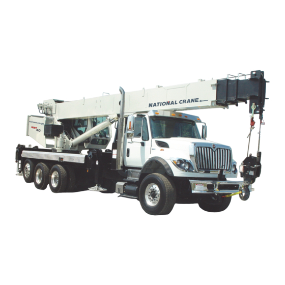
- Page 1 National Crane NBT40 Series Operator Manual...
- Page 3 DANGER An untrained operator subjects himself and others to death or serious injury. Do not operate this crane unless: Manitowoc is not • You are trained in the safe operation of this crane. responsible for qualifying personnel. •...
- Page 4 WARNING California Proposition 65 Breathing diesel engine exhaust exposes you to chemicals known to the State of California to cause cancer and birth defects or other reproductive harm. • Always start and operate the engine in a well- ventilated area. •...
-
Page 5: Table Of Contents
NBT40 SERIES OPERATOR MANUAL TABLE OF CONTENTS SECTION 1 ..........Introduction General . - Page 6 TABLE OF CONTENTS OPERATOR MANUAL NBT40 SERIES Working ............2-33 Lifting .
- Page 7 NBT40 SERIES OPERATOR MANUAL TABLE OF CONTENTS Hoist Rotation Indicator..........3-9 Telescope Control Lever.
- Page 8 TABLE OF CONTENTS OPERATOR MANUAL NBT40 SERIES Terminator Wedge Installation......... 4-7 Wedge Socket Installation .
- Page 9 NBT40 SERIES OPERATOR MANUAL TABLE OF CONTENTS Lubrication ............6-6 Rust Prevention .
- Page 10 TABLE OF CONTENTS OPERATOR MANUAL NBT40 SERIES THIS PAGE BLANK TOC-6...
-
Page 11: Section 1
If you are the new owner of a National Crane, please register performance with minimum maintenance. With proper care, it with Manitowoc Crane Care so we have the ability to years of trouble-free service can be expected. c o n t a c t y o u i f t h e n e e d a r i s e s . G o t o : h t t p s : / / w w w. - Page 12 INTRODUCTION NBT40 SERIES OPERATOR MANUAL FIGURE 1-1 Published 4-23-2018 Control # 239-11...
- Page 13 NBT40 SERIES OPERATOR MANUAL INTRODUCTION 7474-1 7474-5 7474-4 7474-3 7474-2 FIGURE 1-2 Item Component Item Component Boom Angle Indicator Crane Cab Hoist Cable, Wire Rope Crane Cab console Operator’s Seat Turret Boom Stabilizer Front Outrigger (SFO), Front Outrigger Jack Boom Nose Hydraulic Tank Boom Rest Hydraulic Pump (not shown)
- Page 14 Should the National Crane distributor not be immediately available, contact should be made directly with Manitowoc Crane Care. The National Crane must not be returned to service until it is thoroughly inspected for any evidence of damage. All damaged parts must be repaired or replaced as authorized by your local National Crane distributor or Manitowoc Crane Care.
-
Page 15: Safety Messages
NBT40 SERIES OPERATOR MANUAL SAFETY INFORMATION SECTION 2 SAFETY PRECAUTIONS SECTION CONTENTS Safety Messages......2-1 Personnel Handling. -
Page 16: General
Should the distributor not be immediately available, contact should be made directly with Manitowoc Product Safety at the address below. The crane must not be returned to service until it is thoroughly inspected for any evidence of damage. -
Page 17: Operator Qualifications
NBT40 SERIES OPERATOR MANUAL SAFETY INFORMATION No personnel shall be allowed to climb onto the crane or Refer to the Parts Manual for this crane for the locations of all enter the crane cab or operator’s station unless performance safety decals. of their duties require them to do so, and then only with You must be familiar with the regulations and standards knowledge of the operator or other qualified person. -
Page 18: Operational Aids
SAFETY INFORMATION NBT40 SERIES OPERATOR MANUAL As operator of this crane, you are granted the authority to supported personnel platforms. Personnel shall not be stop and refuse to lift loads until safety is assured. lifted when anti-two-block devices are not functioning properly. -
Page 19: Working Area Limiter (If Equipped)
NBT40 SERIES OPERATOR MANUAL SAFETY INFORMATION b o o m e x t e n s i o n n o s e r e s p e c t i v e l y. A n o p e r a t o r, block conditions. -
Page 20: Load Charts
SAFETY INFORMATION NBT40 SERIES OPERATOR MANUAL Use adequate cribbing under outrigger floats to distribute weight over a greater area. Check frequently for settling. Read and follow the following safety decal for cranes with center front stabilizers. KEEP THE BOOM SHORT. Swinging loads with a long line can create an unstable condition and possible structural failure of the boom. -
Page 21: Wind Speeds
NBT40 SERIES OPERATOR MANUAL SAFETY INFORMATION provided to assist in determining safe operation in windy decreased backward stability, wind on the side of the boom conditions. can result in structural damages, etc.) Always use extreme caution when windy conditions exist. Wind forces can exert extreme dynamic loads. - Page 22 SAFETY INFORMATION NBT40 SERIES OPERATOR MANUAL NOTE: This condition is limited to operation with the main In both cases a) and b) above, the lift may also be limited by boom on fully extended outriggers only. the projected wind area of the load Ap and by the wind drag coefficient Cd: This limit can be determined by comparing c) If V(z) is >...
- Page 23 NBT40 SERIES OPERATOR MANUAL SAFETY INFORMATION Simplified Method to Determine Maximum Permissible Wind Speed Determine 3-Second Gust 0.14 V(z) = [(z/10) + 0.4]v [m/s] Wind Speed at boom tip, 0.14 V(z) = [(z/33) + 0.4]v [mph] V(z) 13.4 m/s < V(z) < 20.1 m/s V(z) >...
- Page 24 SAFETY INFORMATION NBT40 SERIES OPERATOR MANUAL Determination of 3-second wind gust speed at boom Size and Shape of the load: tip height: These rated capacities are also based on the assumption that the Wind Resistance Area of load, Awr is not more The following example illustrates how to calculate 3-second (load) wind gust speed at boom tip height based on mean wind...
- Page 25 NBT40 SERIES OPERATOR MANUAL SAFETY INFORMATION Calculation of Projected Wind Area (Ap) Wind Wind = 8 m = 24 m 25 ft 25 ft Wind Wind 10 ft 3 ft = 75 ft = 250 ft 10 ft 3 ft 8384-1 FIGURE 2-2 Determining Wind Drag Coefficient (Cd)
- Page 26 SAFETY INFORMATION NBT40 SERIES OPERATOR MANUAL Table 2-2 Wind Drag Coefficient Maximum Permissible Wind Speed If the wind resistant area of the load Awr is greater than (load) Shape the allowable wind resistant area Awr , the ratio can be (allow) used to determine a permissible wind speed V(z) for the load 1.1 to 2.0...
- Page 27 NBT40 SERIES OPERATOR MANUAL SAFETY INFORMATION Rated Load Chart Example - Metric 8383-1 FIGURE 2-3 National Crane 2-13 Published 4-23-2018 Control # 239-11...
- Page 28 SAFETY INFORMATION NBT40 SERIES OPERATOR MANUAL Table 2-4 Example-Capacity Reduction Factors for Wind Speed V(z) Greater than 13.4 m/s - Metric (Only for lifting with main boom on fully extended outriggers, with or without stowed extension) For wind speed V(z) (3-second gust speed at boom tip height) V(z) > 13.4 m/s ≤ 20.1 m/s, the Reduced Capacity shall be calculated by multiplying the Published Rated Capacity by the following factors: Main Boom Length in Meters Wind Speed...
- Page 29 NBT40 SERIES OPERATOR MANUAL SAFETY INFORMATION At wind speeds greater than 13.4 m/s, it is not permissible to Load example 1.3a: lift a load greater than 12,040 kg, even if the wind resistance With large wind resistance area of the load Awr (load) area of the load is less than 14.45 m •...
- Page 30 SAFETY INFORMATION NBT40 SERIES OPERATOR MANUAL • Is the load to be lifted less than allowable load? Ratio = 1.37 8,000 kg ≤ 12,040 kg • Is Awr less than Awr (load) (allow) From Table 2-5, the maximum permissible wind speed at 19.83 m ≤...
- Page 31 NBT40 SERIES OPERATOR MANUAL SAFETY INFORMATION Rated Load Chart Example - Non-metric 8382-1 FIGURE 2-4 National Crane 2-17 Published 4-23-2018 Control # 239-11...
- Page 32 SAFETY INFORMATION NBT40 SERIES OPERATOR MANUAL Table 2-6 Example-Capacity Reduction Factors for Wind Speed V(z) Greater than 30 mph - Non-metric (Only for lifting with main boom on fully extended outriggers, with or without stowed extension) For wind speed Vz (3-second gust speed at boom tip height) is greater > 30> mph ≤ 45 mph, the Reduced Capacity shall be calculated by multiplying the Published Rated Capacity by the following factors: Main Boom Length in Feet Wind Speed...
- Page 33 NBT40 SERIES OPERATOR MANUAL SAFETY INFORMATION • Is Awr less than Awr (load) (allow) 108 ft ≤ 119 ft L i f t i n g L i m i t s a t w i n d s p e e d V ( z ) > 3 0 m p h Conclusion: This load is permissible to lift in wind speed up and ≤...
-
Page 34: Lifting Operations
SAFETY INFORMATION NBT40 SERIES OPERATOR MANUAL Refer to the above Lifting Limits at wind speed V(z) injury could result from the crane tipping over or failing > 30 mph and ≤ 45 mph. Comparing the load and wind structurally from overload. resistant area to the allowable: The crane can tip over or fail structurally if: •... -
Page 35: Counterweight
NBT40 SERIES OPERATOR MANUAL SAFETY INFORMATION Counterweight • Maintain communication between all parties throughout the entire operation. If possible, provide approved radio On cranes equipped with removable counterweights, ensure equipment for voice communication between all parties the appropriate counterweight sections are properly installed engaged in the lift. -
Page 36: Pile Driving And Extracting
SAFETY INFORMATION NBT40 SERIES OPERATOR MANUAL • The panel shall be lifted so that the hoist lines are in line • The pile driver and piling shall be suspended from a with the crane. hoist cable with sufficient line speed to meet or exceed the rate of descent of the driver and piling to preclude •... -
Page 37: Electrocution Hazard
NBT40 SERIES OPERATOR MANUAL SAFETY INFORMATION ELECTROCUTION HAZARD 29CFR1926.1408 and ASME B30.5 American National Standard. Thoroughly read, understand, and abide by all applicable federal, state, and local regulations regarding operation of cranes near electric power lines or equipment. United States federal law prohibits the use of WARNING cranes closer than 6 m (20 ft) to power sources up to 350 kV and greater distances for higher... -
Page 38: Set-Up And Operation
SAFETY INFORMATION NBT40 SERIES OPERATOR MANUAL The rules in this Operator Manual must be followed at all or load moves near a power source. This person shall have times, even if the electrical power lines or equipment have no other duties while the crane is working. been de-energized. -
Page 39: Electrical Contact
Should the distributor not be immediately • If a thunder storm is forecast available, contact Manitowoc Crane Care. The crane must not be returned to service until it is thoroughly inspected for Use electrically conducting material for grounding. -
Page 40: Personnel Handling
SAFETY INFORMATION NBT40 SERIES OPERATOR MANUAL Connect the free end of the cable with a clamp (1) to a General requirements. The use of a crane or der- rick to hoist employees on a personnel platform is good electrically conductive location on the frame. prohibited, except when the erection, use, and dis- mantling of conventional means of reaching the worksite, such as a personnel hoist, ladder, stair-... -
Page 41: Environmental Protection
NBT40 SERIES OPERATOR MANUAL SAFETY INFORMATION The platform is properly attached and secured to the • Always drain waste fluids into leak proof containers that load hook. are clearly marked with what they contain. • For boom mounted platforms: • Always fill or add fluids with a funnel or a filling pump. -
Page 42: Lubrication
Do not attempt to repair or tighten any hydraulic hose or • Consult with Manitowoc Crane Care to determine if load fitting while the engine is running, or when the hydraulic testing is required after a structural repair is performed. -
Page 43: Tires
K100™ Synthetic Crane Hoist Line Manual P/N • Core deterioration, usually observed as a rapid 9828100734 available by contacting Manitowoc Crane Care. reduction in rope diameter, is cause for immediate removal of the rope. During installation and setup, care must be taken to avoid overlap and crossing of wire rope and synthetic hoist ropes. -
Page 44: Sheaves
SAFETY INFORMATION NBT40 SERIES OPERATOR MANUAL • Never “shock load” a rope. A sudden application of force Evidence of abuse or contact with another object. or load can cause both visible external and internal Heat damage. damage. There is no practical way to estimate the force applied by shock loading a rope. -
Page 45: Batteries
NBT40 SERIES OPERATOR MANUAL SAFETY INFORMATION Engine Ensure sheaves carrying ropes that can be momentarily unloaded are equipped with close fitting guards or other Fuel the crane only with the engine turned off. Do not smoke devices to guide the rope back into the groove when the load while fueling the crane. -
Page 46: Travel Operation
SAFETY INFORMATION NBT40 SERIES OPERATOR MANUAL exercised anytime any crane function is being performed Watch clearances when traveling. Do not take a chance of while the cable is hooked into the hookblock tie down. running into overhead or side obstructions. When moving in tight quarters, post a signal person to help TRAVEL OPERATION guard against collisions or bumping structures. -
Page 47: Work Practices
Operator Manual when extending or retracting the system that have not been evaluated and approved by outriggers. Death or serious injury could result from improper Manitowoc Crane Care. crane set up on outriggers. Do not step on surfaces on the crane that are not approved Be familiar with surface conditions and the presence of or suitable for walking and working. -
Page 48: Lifting
SAFETY INFORMATION NBT40 SERIES OPERATOR MANUAL Sparks from the crane’s electrical system and/or engine exhaust can cause an explosion. Do not operate this crane in an area with flammable dust or vapors, unless good ventilation has removed the hazard. Carbon monoxide fumes from the engine exhaust can cause suffocation in an enclosed area. -
Page 49: Hand Signals
NBT40 SERIES OPERATOR MANUAL SAFETY INFORMATION Be sure the load is well secured and attached to the hook If the boom should contact an object, stop immediately and with rigging of proper size and in good condition. inspect the boom. Remove the crane from service if the boom is damaged. - Page 50 SAFETY INFORMATION NBT40 SERIES OPERATOR MANUAL 8496-1 FIGURE 2-6 2-36 Published 4-23-2018 Control # 239-11...
-
Page 51: Boom Extension
NBT40 SERIES OPERATOR MANUAL SAFETY INFORMATION BOOM EXTENSION that certain jobsite conditions may not permit the boom and boom extension of a crane to be fully lowered to the ground. To avoid death or serious injury, follow the procedures in this When a qualified person at a jobsite determines that it is not manual during erection, stowage, and use of the boom practical to lower the boom to the ground, we recommend... -
Page 52: Temperature Effects On Hook Blocks
SAFETY INFORMATION NBT40 SERIES OPERATOR MANUAL If applicable to your crane, frequently check all air tanks for factors and will be more noticeable with a larger difference in water in freezing weather. oil temperature verses the ambient temperature. Never store flammable materials on the crane. Thermal contraction coupled with improper lubrication or improper wear pad adjustments may, under certain If cold weather starting aids are provided on your crane, use... -
Page 53: Overload Inspection
NBT40 SERIES OPERATOR MANUAL SAFETY INFORMATION Table 2-8: Boom Drift Chart (Cylinder length change in inches) Coeff. = 0.00043 (in / °F) STROKE Temperature Change (°F) (FT.) 0.26 0.52 0.77 1.03 1.29 1.55 1.81 2.06 2.32 2.58 0.52 1.03 1.55 2.06 2.58 3.10... - Page 54 To avoid an accident caused by overload damage to your crane: • Perform the inspections outlined in this publication for overloads up to 50%. • Stop operating the crane and contact Manitowoc Crane Care immediately for overloads of 50% and higher. 2-40 Published 4-23-2018 Control # 239-11...
-
Page 55: Boom Inspection
NBT40 SERIES OPERATOR MANUAL SAFETY INFORMATION Boom Inspection 9, 10 2, 3 9, 10 Illustration for reference only. Your crane may be different. National Crane 2-41 Published 4-23-2018 Control # 239-11... - Page 56 SAFETY INFORMATION NBT40 SERIES OPERATOR MANUAL NOTE: The following checklist includes all features that can be found on Manitowoc cranes. Your crane may not have some features. Overload less than 25% Sheaves, Inspect all for damage. Rope Guides Collar-Wear Pads, Pad Inspect for damage.
-
Page 57: Superstructure Inspection
NBT40 SERIES OPERATOR MANUAL SAFETY INFORMATION Superstructure Inspection 10,11 Illustration for reference only. Your crane may be different. National Crane 2-43 Published 4-23-2018 Control # 239-11... - Page 58 SAFETY INFORMATION NBT40 SERIES OPERATOR MANUAL NOTE: The following checklist includes all features that can be found on Manitowoc cranes. Your crane may not have some features. Overload less than 25% Lift Cylinder Inspect for leaks. See topic in Introduction section Wire Rope Inspect all for damage.
-
Page 59: Carrier Inspection
NBT40 SERIES OPERATOR MANUAL SAFETY INFORMATION Carrier Inspection 5, 6 Illustration for reference only. Your crane may be different. National Crane 2-45 Published 4-23-2018 Control # 239-11... - Page 60 SAFETY INFORMATION NBT40 SERIES OPERATOR MANUAL NOTE: The following checklist includes all features that can be found on Manitowoc cranes. Your crane may not have some features. Overload less than 25% Stabilizer Inspect for leaks. Cylinders Outrigger Inspect for deformation and cracked welds.
-
Page 61: Section 3
NBT40 SERIES OPERATOR MANUAL OPERATING CONTROLS & PROCEDURES SECTION 3 CONTROLS AND OPERATING PROCEDURES SECTION CONTENTS Truck Cab Controls ......3-2 Telescope Control Lever . -
Page 62: Truck Cab Controls
OPERATING CONTROLS & PROCEDURES NBT40 SERIES OPERATOR MANUAL This section contains information on the controls and Power Shift Control operating procedures to include: If the vehicle is equipped with automatic transmission, the • Truck Cab Controls power take-off must be engaged with the engine at idle. See transmission manufacturer ’s instructions for special •... -
Page 63: Outrigger Controls
NBT40 SERIES OPERATOR MANUAL OPERATING CONTROLS & PROCEDURES Item Description Hand Held Outrigger Control Outrigger Control Box Front Center Stabilizer Switch Outrigger Selector Switches Outrigger Bean Selector 7459-1 Extend/Retract Switch Frame Level Indicator Level Indicator 7448-15 Cab Level Indicator Outrigger Controls The outrigger component controls are used to set the outriggers. -
Page 64: Crane Controls
OPERATING CONTROLS & PROCEDURES NBT40 SERIES OPERATOR MANUAL Front Center Stabilizer Switch NOTE: The center front stabilizer automatically retracts if any of the other components are adjusted and The center front stabilizer switch (3, Figure 3-1) is used to must be reset if lifting is to be continued. lower and raise the center front stabilizer. - Page 65 NBT40 SERIES OPERATOR MANUAL OPERATING CONTROLS & PROCEDURES 7462-6 7462-3 FIGURE 3-3 Item Description Handheld Outrigger Control Item Description Swing Brake Pedal Auxiliary Hoist Minimum Wrap Indicator Boom Telescope Pedal (Optional) AC/Heater Vent Foot Throttle Pedal Receptacle (12V) Display Panel Remote Power Switch (Optional) RCL Bypass Switch (Momentary) Crane Power Switch...
-
Page 66: Swing Brake Pedal
OPERATING CONTROLS & PROCEDURES NBT40 SERIES OPERATOR MANUAL 7462-4 7462-5 FIGURE 3-4 Item Description Item Description Boom Lift Control Lever Seat Slide Handle Hoist Up & Down Control (Rotate Indicator) Seat Frame Slide Handle Telescope Boom (Auxiliary Hoist Control) Climate Control Unit Warning Horn Button Level Turret Swing Control Lever... -
Page 67: Rcl And Minimum Wrap Bypass Switch
NBT40 SERIES OPERATOR MANUAL OPERATING CONTROLS & PROCEDURES The hydraulic oil temperature warning light (7, Figure 3-3) is located on the crane cable console and illuminates when the hydraulic oil overheats. If overheating occurs, run the crane DANGER at idle with the controls in neutral until the light goes out. The RCL only aids the operator when properly programmed with the proper load chart and crane configuration. -
Page 68: Emergency Stop Switch
OPERATING CONTROLS & PROCEDURES NBT40 SERIES OPERATOR MANUAL Receptacle This 12 volt accessory outlet (18, Figure 3-3) is located on the lower part of the front control panel and is designed to mate with most 12 volt adapter plugs. Radio Remote Switch (Optional) The radio remote switch (19, Figure 3-4) is used to enable the radio remote controls. -
Page 69: Boom Lift Control Lever
NBT40 SERIES OPERATOR MANUAL OPERATING CONTROLS & PROCEDURES Boom Lift Control Lever Telescope Control Lever The boom lift control lever (29, Figure 3-4) is located on the When equipped without the auxiliary hoist the telescope right armrest and is used to raise and lower the boom. Push boom control lever (31, Figure 3-4) is on the left armrest. -
Page 70: House Lock
OPERATING CONTROLS & PROCEDURES NBT40 SERIES OPERATOR MANUAL and park the turret in position. Press the switch to activate the swing brake to keep the turret from rotating. The swing brake indicator (8, Figure 3-3) is illuminated when the swing brake switch is applied. -
Page 71: Operating Procedures
NBT40 SERIES OPERATOR MANUAL OPERATING CONTROLS & PROCEDURES OPERATING PROCEDURES You need to be familiar with the safety precautions outlined in this manual before operating the crane. Equipment Familiarization All members of the crew should become familiar with the location and operation of the controls, the correct operating procedure, the maximum lifting capacities, and the Safety Precautions in Section 2 of this manual. -
Page 72: Cold Weather Operation
• the RCL and anti-two-block system for proper operation. Always use Manitowoc recommended lubricants and fluids for the prevailing ambient temperature and properly • the electrical wiring connecting the various parts of the start and warm the crane using the cold weather system for physical damage. -
Page 73: Hoist
NBT40 SERIES OPERATOR MANUAL OPERATING CONTROLS & PROCEDURES Hoist and engine immediately and contact a National distributor. Performing a warm-up procedure is recommended at every • From 10°C to 4°C (50°F to 40°F): Crane operation with startup and is required at ambient temperatures below 4°C a load is allowed with medium engine RPM and medium (40°F). -
Page 74: Outrigger Setup
OPERATING CONTROLS & PROCEDURES NBT40 SERIES OPERATOR MANUAL Using the outriggers, level the crane as indicated on the leveling device used in step 3. DANGER Using the bubble level indicator mounting screws, adjust the bubble level indicator to show level. A deviation between displayed and actual values indicates a malfunction and a RCL service representative Setting the Outriggers... -
Page 75: Outrigger Monitoring System (Oms) (Optional-Standard In North America)
NBT40 SERIES OPERATOR MANUAL OPERATING CONTROLS & PROCEDURES Extension/Retraction Switch EXTEND. appropriate stabilizer begins to move. Extend each jack, positioning the float as necessary, WARNING until the locking levers of the float engage the jack Tipping Hazard! cylinder barrel. The mid-extend outrigger beam lock pin must be engaged NOTE: More than one stabilizer can be extended at a time. -
Page 76: Hoist System Operation
OPERATING CONTROLS & PROCEDURES NBT40 SERIES OPERATOR MANUAL • Always have at least three full wraps of rope on the hoist. Startup Graphic • Check the hoist brake when approaching the load limit of the hoist. Raise the load a few inches and return the control to neutral to check the brake. -
Page 77: Stowing And Parking
NBT40 SERIES OPERATOR MANUAL OPERATING CONTROLS & PROCEDURES Shut down the engine following the proper procedures specified in this manual and the applicable engine DANGER manual. Truck must be in neutral when starting engine from crane 10. Remove the keys. cab to avoid sudden potential movement of truck. -
Page 78: Load Chart
OPERATING CONTROLS & PROCEDURES NBT40 SERIES OPERATOR MANUAL release swing brake with boom below minimum indicated boom angle. DANGER This condition is applicable when the load chart does not provide a maximum boom length at 0 degree boom angle in Tipping Hazard! a no load situation. -
Page 79: Lifting The Load
NBT40 SERIES OPERATOR MANUAL OPERATING CONTROLS & PROCEDURES A boom extension capacity chart and notes are included to list the capacities for the extension length, load radius, and boom angle. CAUTION Machine Damage Hazard! Another section contains the notes for lifting capacities. Be sure to read and understand all the notes concerning lifting Do not travel with an empty hook in a position where it can capacities. - Page 80 OPERATING CONTROLS & PROCEDURES NBT40 SERIES OPERATOR MANUAL b. The the A2B weight needs to be resting on the Release the park brake before moving truck. wedge socket so that there is slack in the anti-two- block-chain. NOTE: There needs to be enough slack in the A2B chain so that the A2B switch does not switch between open and close during travel.
-
Page 81: Section 4
NBT40 SERIES OPERATOR MANUAL SET-UP SECTION 4 SET-UP SECTION CONTENTS Jib Safety Information ..... . 4-1 Stow Pegs for hoist cable....4-5 Jib Operation. -
Page 82: Jib Operation
SET-UP NBT40 SERIES OPERATOR MANUAL 11. Always put spring clips in pins to ensure that they will stay in place. CAUTION 12. When the jib is stowed, the boom can not be fully retracted if a boom tip attachment option is installed. Use caution during this step. -
Page 83: Stowing Procedure
NBT40 SERIES OPERATOR MANUAL SET-UP d. Open the jack release valve and retract the jack (F, Using lift function, lower boom so that jib deployment Figure 4-1. pins (C1, Figure 4-1) and (C2, Figure 4-1) are easily accessible from the ground. 14. - Page 84 SET-UP NBT40 SERIES OPERATOR MANUAL JIb in Operating position 7462-27 Stow Pin Jib Swing Pin Jib Deployment Pins Hook Bracket Extension Retaining Pin Jib in Stow Position Jib Jack Jack Handle Jib Stowage Bracket Left Side Right Side 7462-28 FIGURE 4-1 Published 4-23-2018 Control # 239-11...
-
Page 85: Jib Removal
NBT40 SERIES OPERATOR MANUAL SET-UP 14. Using boom telescope function, slowly retract boom. The jib stow bracket (H, Figure 4-1) on the side of the jib Upper Link will engage the side stow bracket (D) on the side of the The A2B bracket must be section boom;... -
Page 86: Multi-Part Line Reeving
The hook block must be sized to the number of line parts. For example, do not use a six part line hook block on a three part line reeving. Contact your National Crane Distributor or Manitowoc Crane Care to order the proper hook block. -
Page 87: Installing Cable On The Hoist
NBT40 SERIES OPERATOR MANUAL SET-UP INSTALLING CABLE ON THE HOIST Slowly rotate the drum, ensuring the first layer of cable is evenly wound onto the drum. NOTE: The cable should preferably be straightened before Install the remainder of the cable, as applicable. CAUTION Attach the wedge socket to the free end of the cable as shown in (Figure 4-6). -
Page 88: Wedge Socket Installation
SET-UP NBT40 SERIES OPERATOR MANUAL • If the wire rope passes through the “no go” hole, the Tighten nuts on clip to recommended torque. wedge is the wrong size. Do not attach dead end to live end or install wedge •... -
Page 89: Dead-End Rigging
6.35 block system and other components during use of the crane. 5/16 7.94 Of the methods shown below, Manitowoc prefers that 13.28 method A or F be used, i.e., clipping a short piece of wire 7/16 11.11 rope to the dead-end or using a commercially available 12.70... - Page 90 SET-UP NBT40 SERIES OPERATOR MANUAL Specialty Clip Specialty Wedge Wedge Socket FIGURE 4-7 4-10 Published 4-23-2018 Control # 239-11...
-
Page 91: Section 5
For information on extreme condition lubrication, contact your local National Potentially harmful waste used in Manitowoc cranes includes Crane Distributor or Manitowoc Crane Care. — but is not limited to — oil, fuel, grease, coolant, air... -
Page 92: Arctic Conditions Below -9°C (15°F)
If you are in doubt about the +10°C (+50°F) suitability of a specific fluid, check with your authorized National Crane distributor or Manitowoc Crane Care. Open Gear Lubricant NOTE: All fluids and lubricants may be purchased by... -
Page 93: Arctic Hydraulic Oil
ISO 17/14 or better cleanliness Arctic Hydraulic Oil level and must meet John Deere Standard JDM J20C. Contact your National Crane distributor or Manitowoc Crane Temperature Down to -9°C (15°F) to -29°C (-20°F) Care if you have any questions. - Page 94 Each lubrication point is numbered, and this number corresponds to the index number shown on the Lubrication Table 5-1 Manitowoc Lube Specification Symbol Description Cold Weather - Standard 40°C (-40°F)
- Page 95 NBT40 SERIES OPERATOR MANUAL LUBRICATION Lubrication Points Grease Tube 7471-1 FIGURE 5-1 Table 5-2 Recommended Item Application Procedure Frequency Lubricant Weekly As Required Semi- Hydraulic oil reservoir Hydraulic Oil Check fill change Annually After first 40 Hrs. As indicated by Oil filter, Hydraulic oil reservoir Change or clean gauge thereafter.
-
Page 96: Boom Lubrication
LUBRICATION NBT40 SERIES OPERATOR MANUAL Recommended Item Application Procedure Frequency Lubricant Turntable bearing EP-MPG Grease gun Weekly Chassis Grease Change After First 100 Operating Hours Pump Drive U-Joint - 2 ea. (If Equipped) Check and Fill Change Weekly Coupling Lube Semi-Annually Pump Spline Shaft (Direct Mount) Spline Lubricant... -
Page 97: Side And Bottom Boom Wear Pad Lubrication
NBT40 SERIES OPERATOR MANUAL LUBRICATION Outrigger Beam Lubrication Locate the fittings as listed in the table above. Lubricate the pins until a small amount of grease extrudes from the pin. DANGER Side and Bottom Boom Wear Pad Do not, under any circumstances, work at an elevated Lubrication height without using proper fall protection as required by local, state or federal regulations. -
Page 98: Hoist Gearbox Oil
Hoist gear lubricants are satisfactory for operation in temperatures from -23° C to 66° C (-10° F to +150° F). For Hoist Gearbox Oil operation outside this range, contact Manitowoc Crane Care for recommendations. Check Hoist Gearbox Oil Level: •... -
Page 99: Swing Gearbox And Brake Oil
3.3 l (3.50 qt) of gear lube oil. Gearbox lubricants are satisfactory for standard operation in temperatures from -23° C to 82° C (-10° F to +180° F). For operation outside this range, contact Manitowoc Crane Care for recommendations. FIGURE 5-6... -
Page 100: Wire Rope Lubrication
LUBRICATION NBT40 SERIES OPERATOR MANUAL lines. Follow the specifications listed on section titled Air • of a viscosity capable of penetrating the interstices Conditioner, page 9-32. between wires and strands. After servicing ensure air conditioning system is re-charged • not be soluble in the medium surrounding it under the with refrigerant and oil according to specifications listed on actual operating conditions (i.e. -
Page 101: Carwell® Rust Inhibitor
To help protect against corrosion of National cranes, techniques. Manitowoc Crane Care recommends washing the crane at least monthly to remove all foreign matter. More frequent This treatment works in various ways: (1) it eliminates the... -
Page 102: Inspection And Repair
• Prepare the surface prior to applying the finish coat of paint. Please contact Manitowoc Crane Care should you have any questions. 5-12 Published 4-23-2018 Control # 239-11... -
Page 103: Areas Of Application
NBT40 SERIES OPERATOR MANUAL LUBRICATION Areas of Application • Superstructure applications are; hose end and fittings, wire rope on hoist roller tensioning springs on hoists, all Refer to Figure 5-8 unpainted fasteners and hardware, valves, slew ring fasteners and all bare metal surfaces. •... - Page 104 LUBRICATION NBT40 SERIES OPERATOR MANUAL 7650-52 7650-53 FIGURE 5-8 5-14 Published 4-23-2018 Control # 239-11...
- Page 105 NBT40 SERIES OPERATOR MANUAL LUBRICATION Item Description Headache Ball/Hook block Item Description O/R Pins, Clips Hoist Plumbing Connections Mirror Mounting Hardware Tension Spring Powertrain Hardware Counterweight Pins O/R Hose Connections All Hardware, Clips, Pins, Hose Connections not painted O/R Pins, Clips Entire underside of unit Valvebank, Hose Connections inside turntable Turntable Bearing Fasteners...
- Page 106 LUBRICATION NBT40 SERIES OPERATOR MANUAL THIS PAGE BLANK 5-16 Published 4-23-2018 Control # 239-11...
-
Page 107: Crane Inspection And Maintenance
An inspection log book is height without using proper fall protection as required by available from your National Crane distributor or local, state or federal regulations Manitowoc Crane Care. Inspections WARNING The inspection intervals listed below are to be conducted on the unit to ensure safe and proper operation. -
Page 108: Inspections
MAINTENANCE CHECKLIST NBT40 SERIES OPERATOR MANUAL Engine oil level. Battery water level. Hydraulic oil level. Tire pressure. Radiator coolant level. Lubrication as specified by the Lubrication, Section 5. Loose parts or damage to structures or welds. Torque the T-box mounting bolts during the first month of operation and periodic inspections thereafter. -
Page 109: Special Boom Inspection
(7) years. or deteriorated insulation and bare wire. Replace or repair wires as required. NOTE: Wire rope may be purchased through Manitowoc Crane Care. 12. Extend and retract cables, sheaves, pins, and bearings for wear or abrasion. -
Page 110: Dynamic Shock Loads
MAINTENANCE CHECKLIST NBT40 SERIES OPERATOR MANUAL Dynamic Shock Loads • Core failure in rotation resistant ropes. • Prior electrical contact with a power line or other electric Subjecting wire rope to abnormal loads beyond the arc damage. endurance limit will shorten the wire rope life expectancy. Examples of this type of loading are listed below. -
Page 111: Wire Rope Replacement
NBT40 SERIES OPERATOR MANUAL MAINTENANCE CHECKLIST or hoist drums can accelerate wear and cause rapid 0.047 in (1.2 mm) for rope diameters 0.561 in (14.3 deterioration of the wire rope. mm) to 0.75 in (19.1 mm) Inspect the eye end of the cable for greater wear than the 0.063 (1.6 mm) for rope diameters 0.875 in (22.2 rest of the cable. -
Page 112: Crane Adjustments And Repairs
When not in use, always leave the saddle and ram system, the replacement cable must be obtained through the all the way down. Manitowoc Crane Care. Extension cables are pre-stretched and have special connections for proper operation HYDRAULIC SYSTEM Jib Jack Service and Maintenance... - Page 113 NBT40 SERIES OPERATOR MANUAL MAINTENANCE CHECKLIST Condition Possible Cause Possible Solution Insure the RCL system is working properly and RCL system inoperative. the anti-two-block solenoid is powered. Load too heavy. Check load chart. PTO not engaged. Engage PTO. Low hydraulic fluid supply. Check and fill as required.
- Page 114 MAINTENANCE CHECKLIST NBT40 SERIES OPERATOR MANUAL Condition Possible Cause Possible Solution Turn circuit relief valves sticking. Clean and check circuit pressure. Turntable bearing drag. Lubricate thoroughly as rotating boom. Swing will not turn Check brake pilot pressure. Clean pilot line or Brake not releasing properly.
-
Page 115: Tire Load And Inflation Table
NBT40 SERIES OPERATOR MANUAL MAINTENANCE CHECKLIST Condition Possible Cause Possible Solution Check fuse at crane cab console. Replace if Blown fuse. System is in a state of necessary. constant cut-out. ATB switch open. Ensure that ATB switch is closed. System cuts out too early or RCL programmed wrong. - Page 116 MAINTENANCE CHECKLIST NBT40 SERIES OPERATOR MANUAL Radial Ply Metric Tires for Trucks, Busses, and Trailers Used in Normal Highway Service Radial Ply Tires Mounted on 15° Drop Center Rims Tire and Rim Association Standard 6-10 Published 4-23-2018 Control # 239-11...
- Page 117 NBT40 SERIES OPERATOR MANUAL MAINTENANCE CHECKLIST Radial Ply Metric Tires for Trucks, Busses, and Trailers Used in Normal Highway Service Radial Ply Tires Mounted on 15° Drop Center Rims Tire and Rim Association Standard Radial Ply Metric Tires for Trucks, Busses, and Trailers Used in Normal Highway Service Radial Ply Tires Mounted on 15°...
- Page 118 MAINTENANCE CHECKLIST NBT40 SERIES OPERATOR MANUAL Metric Wide Base Tires for Trucks, Busses, and Trailers Used in Normal Highway Service Tires Used as Singles Mounted on 15° Drop Center Rims Tire and Rim Association Standard Radial Ply Tires for Trucks, Busses, and Trailers Used in Normal Highway Service Radial Ply Tires Mounted on 15°...
-
Page 119: Specifications
NBT40 SERIES OPERATOR MANUAL MAINTENANCE CHECKLIST SPECIFICATIONS Hydraulic Hydraulic Pump..............75.5 gpm (286 1/min) at 2200 rpm, Variable displacement, axial piston with load sense Displacement ..............8.54 in /rev (140 cc/rev) Pressure Rating (rated)..........4600 psi (320 bar) Pressure Rating (peak ...........5075 psi (350 bar) Case Refill Capacity............37 gal (1.40 liter) Minimum Operating Speed ..........600 rpm Outrigger System ..............3250 (+/-100) psi... -
Page 120: Counterweight
MAINTENANCE CHECKLIST NBT40 SERIES OPERATOR MANUAL Line Speed (no load at high engine idle speed) Layer Low Speed m/sec (ft/sec) High Speed m/sec (ft/sec) 43.9 (144) 87.5 (287) 48.5 (159) 97.2 (319) 53.3 (175) 107.0 (351) 58.2 (191) 116.7 (383) 63.1 (207) 126.5 (415) Crane Operating Speeds... - Page 121 NBT40 SERIES OPERATOR MANUAL MAINTENANCE CHECKLIST 142 ft Boom................14,338 lbs (6,504kg) 161 ft Boom................17,526 lbs (7,950kg) National Crane 6-15 Published 4-23-2018 Control # 239-11...
-
Page 122: Dimensional Drawing
MAINTENANCE CHECKLIST NBT40 SERIES OPERATOR MANUAL DIMENSIONAL DRAWING 7488-5 7488-3 FIGURE 6-2 6-16 Published 4-23-2018 Control # 239-11... - Page 123 NBT40 SERIES OPERATOR MANUAL MAINTENANCE CHECKLIST 7488-4 7488-6 National Crane 6-17 Published 4-23-2018 Control # 239-11...
- Page 124 MAINTENANCE CHECKLIST NBT40 SERIES OPERATOR MANUAL THIS PAGE BLANK 6-18 Published 4-23-2018 Control # 239-11...
- Page 125 NBT40 SERIES OPERATOR MANUAL Accidents ............. 2-2 Air Conditioning .
- Page 126 OPERATOR MANUAL NBT40 SERIES THIS PAGE BLANK APL- 2...
Need help?
Do you have a question about the National Crane NBT40 Series and is the answer not in the manual?
Questions and answers