Table of Contents
Advertisement
Quick Links
Advertisement
Table of Contents

Related Manuals for Manitowoc National Crane NBT50 Series


Summary of Contents for Manitowoc National Crane NBT50 Series
- Page 1 National Crane NBT50 Series Operator Manual...
- Page 3 An untrained operator subjects himself and others to death or serious injury. Do not operate this crane unless: • You have been trained in the safe operation of this crane. Manitowoc is not responsible for qualifying personnel • You read, understand, and follow the safety and operating recommendations contained in the crane manufacturer’s manuals and...
- Page 4 WARNING California Proposition 65 Breathing diesel engine exhaust exposes you to chemicals known to the State of California to cause cancer and birth defects or other reproductive harm. • Always start and operate the engine in a well- ventilated area. •...
-
Page 5: Table Of Contents
NBT50 OPERATOR MANUAL TABLE OF CONTENTS SECTION 1 ..........Introduction General . - Page 6 TABLE OF CONTENTS OPERATOR MANUAL NBT50 Working ............2-33 Lifting .
- Page 7 NBT50 OPERATOR MANUAL TABLE OF CONTENTS Dual Axis Controller (Boom Lift/Main Hoist) ......3-11 Dual Axis Controller (Swing/Tele/Aux Hoist).
- Page 8 TABLE OF CONTENTS OPERATOR MANUAL NBT50 Stowing Procedure ..........4-7 Jib Removal .
- Page 9 NBT50 OPERATOR MANUAL TABLE OF CONTENTS Stability ............6-3 Hoist Cable Inspection And Maintenance .
- Page 10 TABLE OF CONTENTS OPERATOR MANUAL NBT50 THIS PAGE BLANK TOC-6...
-
Page 11: Section 1
(HCAS), a safe load indicator (SLI), or for the latest information. Your National Distributor is an ECS5; Manitowoc refers to these systems as a rated equipped with the proper tools, necessary parts, and trained capacity limiter (RCL) throughout its Operator and Service personnel to properly maintain and service your crane. - Page 12 INTRODUCTION OPERATOR MANUAL NBT50 7650-66 FIGURE 1-1 Published 03-23-2018 Control # 243-14...
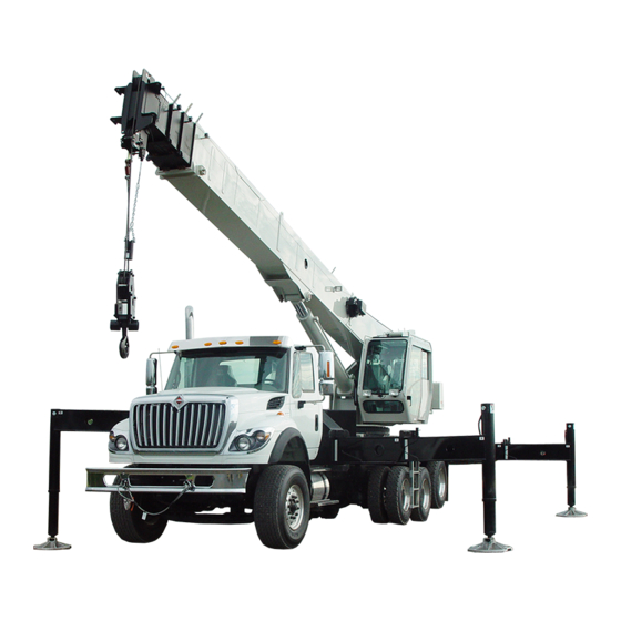
- Page 13 NBT50 OPERATOR MANUAL INTRODUCTION FIGURE 1-2 7449-1 7449-2 7765 Item Component Cab Crane Controls (Inside Cab) RCL, Display Screen (Inside Cab) Rated Capacity Limiter (RCL) Reel 7450 Boom Boom Nose Item Component Boom Rest Ground Outrigger Control Lift Cylinder Hydraulic Pump Main Hoist (front) Cab Outrigger Control (Inside Cab) Auxiliary Hoist (rear)
-
Page 14: New Owner
New Owner https://www.manitowoccranes.com/en/Parts_Services/ Servic eAndSupport /Cha ngeOf Own ership Form If you are the new owner of a Manitowoc crane, please complete the form. register it with Manitowoc Crane Care so we have the ability to contact you if the need arises. Go to:... -
Page 15: Safety Messages
NBT50 OPERATOR MANUAL SAFETY PRECAUTIONS SECTION 2 SAFETY PRECAUTIONS Environmental Protection....2-27 Safety Messages......2-1 General . -
Page 16: General
ACCIDENTS Following any accident or damage to equipment, the WARNING Manitowoc distributor must be immediately advised of the Identifies hazards that may result in death or serious incident and consulted on necessary inspections and injury if the message is ignored. -
Page 17: Operator Qualifications
NBT50 OPERATOR MANUAL SAFETY PRECAUTIONS No personnel shall be allowed to climb onto the crane or Refer to the Parts Manual for this crane for the locations of all enter the crane cab or operator’s station unless performance safety decals. of their duties require them to do so, and then only with You must be familiar with the regulations and standards knowledge of the operator or other qualified person. -
Page 18: Operational Aids
(HCAS), a safe load indicator (SLI), or the designated person responsible for supervising the an EKS5; Manitowoc refers to these systems as a rated lifting operations shall establish procedures for capacity limiter (RCL) throughout its Operator and Service determining load weights and shall ascertain that the Manuals.) -
Page 19: Working Area Limiter (If Equipped)
NBT50 OPERATOR MANUAL SAFETY PRECAUTIONS Two-blocking is more likely to occur when both the main and intended to assist the operator in preventing dangerous two- auxiliary hoist lines are reeved over the main boom nose and block conditions. It is not a replacement for operator b o o m e x t e n s i o n n o s e r e s p e c t i v e l y. -
Page 20: Load Charts
SAFETY PRECAUTIONS NBT50 OPERATOR MANUAL outriggers must also be pinned when operating from the mid- extend position. Use adequate cribbing under outrigger floats to distribute weight over a greater area. Check frequently for settling. Read and follow the following safety decal for cranes with center front stabilizers. -
Page 21: Wind Speeds
Always use extreme caution when windy conditions exist. Wind forces can exert extreme dynamic loads. Manitowoc NEVER exceed the rated capacity shown on the Load Chart. recommends that a lift not be made if the wind can cause a loss of control in handling the load. - Page 22 SAFETY PRECAUTIONS NBT50 OPERATOR MANUAL NOTE: This condition is limited to operation with the main In both cases a) and b) above, the lift may also be limited by boom on fully extended outriggers only. the projected wind area of the load Ap and by the wind drag coefficient Cd: This limit can be determined by comparing c) If V(z) is >...
- Page 23 NBT50 OPERATOR MANUAL SAFETY PRECAUTIONS Simplified Method to Determine Maximum Permissible Wind Speed Determine 3-Second Gust 0.14 V(z) = [(z/10) + 0.4]v [m/s] Wind Speed at boom tip, 0.14 V(z) = [(z/33) + 0.4]v [mph] V(z) 13.4 m/s < V(z) < 20.1 m/s V(z) >...
- Page 24 Use tag lines when the wind gust speed is above 13.4 m/s (30 mph) to help control the movement of the Metric, with Z [m] and V [m/s] load. Manitowoc recommends that a lift not be made if 0.14 V(z) = [(Z/10) + 0.4] x V...
- Page 25 NBT50 OPERATOR MANUAL SAFETY PRECAUTIONS Calculation of Projected Wind Area (Ap) Wind Wind = 8 m = 24 m 25 ft 25 ft Wind Wind 10 ft 3 ft = 75 ft = 250 ft 10 ft 3 ft 8384-1 FIGURE 2-2 Determining Wind Drag Coefficient (Cd) If the exact Wind Drag Coefficient of a shape is not known,...
- Page 26 SAFETY PRECAUTIONS NBT50 OPERATOR MANUAL Table 2-2 Wind Drag Coefficient Maximum Permissible Wind Speed If the wind resistant area of the load Awr is greater than (load) Shape the allowable wind resistant area Awr , the ratio can be (allow) used to determine a permissible wind speed V(z) for the load 1.1 to 2.0 using Table 2-3.
- Page 27 NBT50 OPERATOR MANUAL SAFETY PRECAUTIONS Rated Load Chart Example - Metric 8383-1 FIGURE 2-3 NATIONAL CRANE 2-13 Published 03-23-2018 Control # 243-14...
- Page 28 SAFETY PRECAUTIONS NBT50 OPERATOR MANUAL Table 2-4 Example-Capacity Reduction Factors for Wind Speed V(z) Greater than 13.4 m/s - Metric (Only for lifting with main boom on fully extended outriggers, with or without stowed extension) For wind speed V(z) (3-second gust speed at boom tip height) V(z) > 13.4 m/s ≤ 20.1 m/s, the Reduced Capacity shall be calculated by multiplying the Published Rated Capacity by the following factors: Main Boom Length in Meters Wind Speed...
- Page 29 NBT50 OPERATOR MANUAL SAFETY PRECAUTIONS At wind speeds greater than 13.4 m/s, it is not permissible to Load example 1.3a: lift a load greater than 12,040 kg, even if the wind resistance With large wind resistance area of the load Awr (load) area of the load is less than 14.45 m •...
- Page 30 SAFETY PRECAUTIONS NBT50 OPERATOR MANUAL • Is the load to be lifted less than allowable load? Ratio = 1.37 8,000 kg ≤ 12,040 kg • Is Awr less than Awr (load) (allow) From Table 2-5, the maximum permissible wind speed at 19.83 m ≤...
- Page 31 NBT50 OPERATOR MANUAL SAFETY PRECAUTIONS Rated Load Chart Example - Non-metric 8382-1 FIGURE 2-4 NATIONAL CRANE 2-17 Published 03-23-2018 Control # 243-14...
- Page 32 SAFETY PRECAUTIONS NBT50 OPERATOR MANUAL Table 2-6 Example-Capacity Reduction Factors for Wind Speed V(z) Greater than 30 mph - Non-metric (Only for lifting with main boom on fully extended outriggers, with or without stowed extension) For wind speed Vz (3-second gust speed at boom tip height) is greater > 30> mph ≤ 45 mph, the Reduced Capacity shall be calculated by multiplying the Published Rated Capacity by the following factors: Main Boom Length in Feet Wind Speed...
- Page 33 NBT50 OPERATOR MANUAL SAFETY PRECAUTIONS • Is Awr less than Awr (load) (allow) 108 ft ≤ 119 ft L i f t i n g L i m i t s a t w i n d s p e e d V ( z ) > 3 0 m p h Conclusion: This load is permissible to lift in wind speed up and ≤...
-
Page 34: Lifting Operations
SAFETY PRECAUTIONS NBT50 OPERATOR MANUAL Refer to the above Lifting Limits at wind speed V(z) injury could result from the crane tipping over or failing > 30 mph and ≤ 45 mph. Comparing the load and wind structurally from overload. resistant area to the allowable: The crane can tip over or fail structurally if: •... -
Page 35: Counterweight
The “balance point” for stability testing perform tilt-up panel lifting with two hoist lines poses new and according to SAE and Manitowoc criteria is a condition of different hazards than does normal lifting use. loading wherein the load moment acting to overturn the... -
Page 36: Pile Driving And Extracting
• All hoist hooks shall be equipped with a positive locking latch. It is not the intention of Manitowoc to recommend specific types or makes of pile driving and pile extraction equipment, Crane Inspection but rather to advise of the operational requirements to help avoid the detrimental effects that pile driving and pile •... -
Page 37: Electrocution Hazard
WARNING Electrocution Hazard! Thoroughly read, understand, and abide by all applicable Manitowoc cranes are not equipped with all features federal, state, and local regulations regarding operation of required to operate within OSHA 29CFR1926.1408, Table cranes near electric power lines or equipment. -
Page 38: Set-Up And Operation
SAFETY PRECAUTIONS NBT50 OPERATOR MANUAL everyone in, on, and around the crane can be seriously United States OSHA regulations require a flagman when injured or killed. operating in close proximity to energized power lines. Most overhead power lines are not insulated. Treat all Appoint a reliable and qualified signal person, equipped with overhead power lines as being energized unless you have a loud signal whistle or horn and voice communication... -
Page 39: Electrical Contact
Use electrically conducting material for earthing. any evidence of damage and all damaged parts are repaired or replaced as authorized by your Manitowoc distributor or Manitowoc Crane Care. NATIONAL CRANE... -
Page 40: Personnel Handling
ASME B30.5, Mobile and Locomotive Cranes, ASME B30.8, Floating Cranes and Floating Derricks, and in OSHA regulations 29CFRI910.180 for General Industry and 29CFRI926.1431 for Construction. Use of a Manitowoc crane to handle personnel is acceptable provided: • The requirements of the applicable national, state and local regulations and safety codes are met. -
Page 41: Environmental Protection
Manitowoc reminds crane owners to ensure that all safety • NEVER get on or off a moving crane. decals are in place and legible. Manitowoc continues to urge crane owners to upgrade their cranes with rated capacity • NEVER allow anyone other than the operator to be on limiter and control lever lockout systems for all lifting this crane while the machine is operating or traveling. -
Page 42: Service And Repairs
• Consult with Manitowoc Crane Care to determine if load will penetrate the skin, causing serious injury or death. testing is required after a structural repair is performed. -
Page 43: Tires
Each type of fitting attached to a rope has a specific efficiency rating which can reduce the working load of Use only the rope specified by Manitowoc as indicated on the rope assembly or rope system. the crane’s Load Chart. Substitution of an alternate rope may require the use of a different permissible line pull and, therefore, require different reeving. -
Page 44: Sheaves
SAFETY PRECAUTIONS NBT50 OPERATOR MANUAL • Never overload a rope. This means never use the rope Rope stretch (elongation). where the load applied to it is greater than the working Integrity of end attachments. load determined by the rope manufacturer. Evidence of abuse or contact with another object. -
Page 45: Batteries
NBT50 OPERATOR MANUAL SAFETY PRECAUTIONS Engine weekly. Inoperable, damaged and/or worn sheaves cause rapid deterioration of rope. Fuel the crane only with the engine turned off. Do not smoke Ensure sheaves carrying ropes that can be momentarily while fueling the crane. Do not store flammable materials on unloaded are equipped with close fitting guards or other the crane. -
Page 46: Travel Operation
SAFETY PRECAUTIONS NBT50 OPERATOR MANUAL exercised anytime any crane function is being performed Before traveling a crane, check suitability of proposed route while the cable is hooked into the hookblock tie down. with regard to crane height, width, and length. Never back up without the aid of a signal person to verify the TRAVEL OPERATION area behind the crane is clear of obstructions and/or... -
Page 47: Work Practices
Operator Manual when extending or retracting the system that have not been evaluated and approved by outriggers. Death or serious injury could result from improper Manitowoc Crane Care. crane set up on outriggers. Do not step on surfaces on the crane that are not approved Be familiar with surface conditions and the presence of or suitable for walking and working. -
Page 48: Lifting
SAFETY PRECAUTIONS NBT50 OPERATOR MANUAL Sparks from the crane’s electrical system and/or engine exhaust can cause an explosion. Do not operate this crane in an area with flammable dust or vapors, unless good ventilation has removed the hazard. Carbon monoxide fumes from the engine exhaust can cause suffocation in an enclosed area. -
Page 49: Hand Signals
NBT50 OPERATOR MANUAL SAFETY PRECAUTIONS Be sure the load is well secured and attached to the hook If the boom should contact an object, stop immediately and with rigging of proper size and in good condition. inspect the boom. Remove the crane from service if the boom is damaged. - Page 50 SAFETY PRECAUTIONS NBT50 OPERATOR MANUAL 8496-1 FIGURE 2-6 2-36 Published 03-23-2018 Control # 243-14...
-
Page 51: Boom Extension
These instructions are damaged when attempting to free a frozen crane. intended to allow the crane to be placed in the most stable and secure position. However, Manitowoc recognizes that NATIONAL CRANE 2-37... -
Page 52: Temperature Effects On Hook Blocks
SAFETY PRECAUTIONS NBT50 OPERATOR MANUAL If applicable to your crane, frequently check all air tanks for factors and will be more noticeable with a larger difference in water in freezing weather. oil temperature verses the ambient temperature. Never store flammable materials on the crane. Thermal contraction coupled with improper lubrication or improper wear pad adjustments may, under certain If cold weather starting aids are provided on your crane, use... -
Page 53: Model Specific Information
On cranes equipped with a boom mounted personnel crane. platform, use only a platform approved by Manitowoc. These inspections apply only to overloads up to 50%. For overloads of 50% or higher, crane operation must be... - Page 54 To avoid an accident caused by overload damage to your crane: • Perform the inspections outlined in this publication for overloads up to 50%. • Stop operating the crane and contact Manitowoc Crane Care immediately for overloads of 50% and higher. 2-40 Published 03-23-2018 Control # 243-14...
-
Page 55: Boom Inspection
NBT50 OPERATOR MANUAL SAFETY PRECAUTIONS Boom Inspection 8670-2 9, 10 2, 3 9, 10 Illustration for reference only. Your crane may be different. 8238-1 NATIONAL CRANE 2-41 Published 03-23-2018 Control # 243-14... - Page 56 SAFETY PRECAUTIONS NBT50 OPERATOR MANUAL NOTE: The following checklist includes all features that can be found on Manitowoc cranes. Your crane may not have some features. Overload less than 25% Sheaves, Inspect all for damage. Rope Guides Collar-Wear Pads, Pad Inspect for damage.
-
Page 57: Superstructure Inspection
NBT50 OPERATOR MANUAL SAFETY PRECAUTIONS Superstructure Inspection 10,9 7920-1 Illustration for reference only. 8238-1 Your crane may be different. NATIONAL CRANE 2-43 Published 03-23-2018 Control # 243-14... - Page 58 SAFETY PRECAUTIONS NBT50 OPERATOR MANUAL NOTE: The following checklist includes all features that can be found on Manitowoc cranes. Your crane may not have some features. Overload less than 25% Lift Cylinder Inspect for leaks. See topic in Introduction section Wire Rope Inspect all for damage.
-
Page 59: Carrier Inspection
NBT50 OPERATOR MANUAL SAFETY PRECAUTIONS Carrier Inspection Carrier Frame 8283-3 5, 6 Illustration for reference only. Your crane may be different. 8238-1 NATIONAL CRANE 2-45 Published 03-23-2018 Control # 243-14... - Page 60 SAFETY PRECAUTIONS NBT50 OPERATOR MANUAL NOTE: The following checklist includes all features that can be found on Manitowoc cranes. Your crane may not have some features. Overload less than 25% Stabilizer Inspect for leaks. Cylinders Outrigger Inspect for deformation and cracked welds.
-
Page 61: Section 3
NBT50 OPERATOR MANUAL CONTROLS AND OPERATING PROCEDURES SECTION 3 CONTROLS AND OPERATING PROCEDURES SECTION CONTENTS Crane Theory of Operation ....3-2 Seat Back Adjustment ..... 3-11 Crane Software Overview . -
Page 62: Crane Theory Of Operation
CONTROLS AND OPERATING PROCEDURES OPERATOR MANUAL NBT50 Operation....... 3-24 Crane Remote Control (optional) ... . . 3-25 Crane Remote Control Activation. -
Page 63: Truck Cab Controls
NBT50 OPERATOR MANUAL CONTROLS AND OPERATING PROCEDURES switches must be OFF first before changing between states truck gear shift lever must be in neutral and the clutch 1 and 2. depressed whenever the knob is moved. Control States Air Shift Control Much like the Ignition States, Crane Control States allow for The PTO is engaged when the switch is moved to apply air to the crane to be operated in different ways depending on the... -
Page 64: Crane Level Indicators
CONTROLS AND OPERATING PROCEDURES OPERATOR MANUAL NBT50 Crane Level Indicators Item Description A bubble level indicator is located inside the cab near the Retract O/R right side armrest. This indicator provides the operator with a Extend O/R visual indication for determining how level the crane is when operating the outriggers. - Page 65 NBT50 OPERATOR MANUAL CONTROLS AND OPERATING PROCEDURES Outrigger Beam Selector Switch the extend/retract switch to control the operation of the cen- ter front stabilizer. The center front stabilizer will retract auto- The outrigger beam selector switch (1, Figure 3-2) is used to matically when any of the other four jacks are retracted;...
- Page 66 CONTROLS AND OPERATING PROCEDURES OPERATOR MANUAL NBT50 7459-16 7459-1 7448-1 7448-4 FIGURE 3-3 Item Description Item Description Outrigger Midspan Selector Pin Outrigger Stabilizer & Jack Cylinder Outrigger Beam Assy Long Ground Station Outrigger Controls Outrigger Beam Assy Short Outrigger Extend/Retract Cylinder Level Indicator (inside cab) Level Indicator Published 03-23-2018 Control # 243-14...
-
Page 67: Crane Controls
NBT50 OPERATOR MANUAL CONTROLS AND OPERATING PROCEDURES CRANE CONTROLS 7459-2 21 20 19 18 17 7459-3 7805 FIGURE 3-4 Item Description Item Description Outrigger Control Box Diagnostic Connector Swing Brake Pedal Crane Level Indicator Boom Telescope Pedal (Optional) Truck Engine Hi/Low Switch Foot Throttle Pedal Crane Function Power Switch Display Panel Assembly... - Page 68 CONTROLS AND OPERATING PROCEDURES OPERATOR MANUAL NBT50 7459-7 7459-22 7459-23 FIGURE 3-5 Item Description Item Description Swing Horn Button Dual Axis Controller- Boom Lift/Main Hoist AC/Heater Climate Control Unit Dual Axis Controller- Swing/Tele/ Aux Hoist Single Axis Controller-Boom Lift Lever Seat Belt Single Axis Controller- Main Hoist Lever Seat Back Adjustment...
-
Page 69: Outrigger Control Box
NBT50 OPERATOR MANUAL CONTROLS AND OPERATING PROCEDURES Swing Horn Button The crane controls are located in the crane cab and are used for all crane functions. See (Figure 3-4 & Figure 3-5) for The swing horn button (33, Figure 3-5) is located on the cab crane cab item number (#) identification. -
Page 70: Emergency Stop Switch
Contact Manitowoc Crane Care to obtain the to the OFF position. appropriate diagnostic cable. -
Page 71: Skylight Wiper Switch
NBT50 OPERATOR MANUAL CONTROLS AND OPERATING PROCEDURES Skylight Wiper Switch Swing/Telescope - Move the lever left to swing left (counterclockwise). Move the lever right to swing right The skylight wiper switch (20, Figure 3-4) is located in the (clockwise). Positioning the lever forward telescopes the overhead console. -
Page 72: Minimum Wrap Indicator
CONTROLS AND OPERATING PROCEDURES OPERATOR MANUAL NBT50 control module. Each hoist control lever pulses when its hoist machine. Turn the valve knob clockwise to increase and is running so the operator’s thumb can sense it. counterclockwise to decrease speed. The hoist drum rotation indicator (DRI) and Minimum Wrap 7459-9 Indicator (MWI) are integrated into one monitoring system located on the left side of the hoist. -
Page 73: Heater Cold Weather Fuel Mixture
NBT50 OPERATOR MANUAL CONTROLS AND OPERATING PROCEDURES Heater Coolant The heater coolant bottle (1, Figure 3-10) is mounted to the WARNING turret frame. The coolant should contain a minimum 50/50 Explosion Hazard! ratio mixture of water and antifreeze to prevent freezing or Do not mix gasoline with diesel fuel. -
Page 74: Operating Procedures
CONTROLS AND OPERATING PROCEDURES OPERATOR MANUAL NBT50 OPERATING PROCEDURES You need to be familiar with the safety precautions outlined in the section titled Safety Precautions, page 2-1 before operating the crane. Equipment Familiarization All members of the crew should become familiar with the location and operation of the controls, the correct operating procedures, the maximum lifting capacities, and the Safety Precautions in Section 2 of this manual. -
Page 75: Cold Weather Operation
Lubrication section of your crane’s Operator Manual, by contacting your local Manitowoc distributor, or by contacting Hoist Manitowoc Crane Care directly). Performing a warm-up procedure is recommended at every startup and is required at ambient temperatures below 4°C... -
Page 76: Swing Drive And Turntable Bearing
Check that the display of the operating radius of the crane’s hydraulic pumps or motors, stop the operation crane agrees with the actual radius. and engine immediately and contact a Manitowoc distributor. Check the load display by lifting a load of known weight. The accuracy of the load indication shall be within the tolerance of SAE J159. -
Page 77: Hoist System Operation
NBT50 OPERATOR MANUAL CONTROLS AND OPERATING PROCEDURES • Turn the truck cab ignition switch to OFF. DANGER DANGER A deviation between displayed and actual values Truck must be in neutral with the park brake set before indicates a malfunction and a RCL service representative starting engine from crane cab to avoid sudden potential shall be called for repair and/or recalibration of RCL movement of truck. -
Page 78: Unattended Crane
CONTROLS AND OPERATING PROCEDURES OPERATOR MANUAL NBT50 Using the Load Chart CAUTION The load chart is stored in a pocket in the crane cab. The To avoid possible engine fault codes and undesirable load chart contains lifting capacities of the crane in all operation, ensure the keyswitch has been off 2 minutes allowable lifting configurations. -
Page 79: Lifting The Load
NBT50 OPERATOR MANUAL CONTROLS AND OPERATING PROCEDURES SHUT DOWN AND PREPARATION FOR • The range diagram (Figure 3-13) shows the operating radius and the height from horizontal of the unloaded ROAD TRAVEL boom. • The hoist data chart (Figure 3-14) shows hoist capacity CAUTION and multipart line reeving. - Page 80 CONTROLS AND OPERATING PROCEDURES OPERATOR MANUAL NBT50 The A2B weight needs to be resting on the wedge 15. Ensure tires are properly inflated. socket so that there is slack in the anti-two-block- 16. Disengage the Power Take Off (PTO) and start truck chain.
- Page 81 NBT50 OPERATOR MANUAL CONTROLS AND OPERATING PROCEDURES FIGURE 3-13 National Crane 3-21 Published 03-23-2018 Control # 243-14...
- Page 82 CONTROLS AND OPERATING PROCEDURES OPERATOR MANUAL NBT50 FIGURE 3-14 3-22 Published 03-23-2018 Control # 243-14...
-
Page 83: Standard Remote Control
NBT50 OPERATOR MANUAL CONTROLS AND OPERATING PROCEDURES STANDARD REMOTE CONTROL When the standard Remote Control (1) is in the stowed position as shown in Figure 3-15 the remote control power The National Crane model NBT50 is equipped with a cord (3, Figure 3-15) should be plugged into the remote standard hand held radio remote control. -
Page 84: Operation
CONTROLS AND OPERATING PROCEDURES OPERATOR MANUAL NBT50 Operation Item Description Main Hoist Up Auxiliary Hoist Up Center Front Stabilizer Retract Blank Frequency Change Stop/Off The remote control operates only when the crane is running and the “Crane Power” switch is turned OFF, the boom length is less than 10ft extended, and the boom angle is less than 10 degrees. -
Page 85: Crane Remote Control (Optional)
NBT50 OPERATOR MANUAL CONTROLS AND OPERATING PROCEDURES CRANE REMOTE CONTROL (OPTIONAL) 7648 FIGURE 3-18 The optional Crane Remote Control (Figure 3-18) will allow Item Description full remote control of the crane. The standard Remote Main Hoist High Speed Control is disabled when using the optional Crane Remote Control. -
Page 86: Crane Remote Control Activation
CONTROLS AND OPERATING PROCEDURES OPERATOR MANUAL NBT50 The LCD Screen (27, Figure 3-18 and Figure 3-19) on the When finished with the remote, press the red STOP button display is used to communicate signal strength, battery level, (10). This will shut off the machine. If the remote is left turned wireless channel, remote status, and the configuration of the ON for more than 60 minutes, the remote will shut itself off. - Page 87 NBT50 OPERATOR MANUAL CONTROLS AND OPERATING PROCEDURES Use of rechargeable batteries or standard AA batteries is acceptable; however, the batteries can not be charged in the DANGER remote itself. Be sure to turn off the remote by pressing the red stop button to de-activate the controls in order to prevent crane f r o m f u n c t i o n i n g i f t h e c o n t r o l l e r s w i t c h e s a r e inadvertently depressed or bumped during storage.
- Page 88 CONTROLS AND OPERATING PROCEDURES OPERATOR MANUAL NBT50 THIS PAGE BLANK 3-28 Published 03-23-2018 Control # 243-14...
-
Page 89: Section 4
NBT50 OPERATOR MANUAL SET-UP SECTION 4 SET-UP SECTION CONTENTS Outrigger Setup ......4-1 Jib Maintenance......4-9 Proper Leveling of the Crane . -
Page 90: Site Selection
SET-UP OPERATOR MANUAL NBT50 Using the outriggers, level the crane as indicated on the Set all four outrigger beams to: leveling device used in step 3. the fully retracted position. Does not require the Using the bubble level indicator mounting screws, adjust outrigger beams to be extended. -
Page 91: Jib Safety Information
NBT50 OPERATOR MANUAL SET-UP JIB SAFETY INFORMATION 12. Do not extend/retract boom unless boom is horizontal when stow pin (1, Figure 4-3) and jib swing pin (5) are Ensure the proper jib mode is selected in the RCL. removed during stowing or unstowing procedures. The anti-two block (A2B) switch weight and cord must 13. -
Page 92: Jib Operation
SET-UP OPERATOR MANUAL NBT50 Attach tag line to sheave case end of jib. Using the lift function, raise the boom to the horizontal position. CAUTION Use caution during this step. The jib is free to swing away from the boom during boom extension. 10. - Page 93 NBT50 OPERATOR MANUAL SET-UP 13. Use the alignment jack (10, Figure 4-3) to align lower left 15. Route loadline over jib sheave and install keeper. Install side attachment pin (7, Figure 4-3). line block to end of loadline. Remove the jack handle (8, Figure 4-4) from the 16.
- Page 94 SET-UP OPERATOR MANUAL NBT50 Stow Pin Jib Stowage Bracket Hook Bracket Boom Jib Swing Pin Right Side Attachment Pins Left Side Attachment Pins Jib Retaining Pin Alignment Jack FIGURE 4-3 Published 03-23-2018 Control # 243-14...
-
Page 95: Stowing Procedure
NBT50 OPERATOR MANUAL SET-UP FIGURE 4-4 Item Description Stowing Procedure Boom Base Section NOTE: The hoist cable must be routed over the mast assembly and under the roller on the mast for all Tele 1 configurations. Tele 2 NOTE: Depending on the length of the jib being used, the Tele 3 crane can be equipped with either a two section or Jib Swing Pin... -
Page 96: Jib Removal
SET-UP OPERATOR MANUAL NBT50 CAUTION DANGER Always use proper eye protection during this step. Visually check all pin positions and make sure the jib is 10. Raise the boom to the horizontal position. fully retracted into side stow brackets, jib stow attachment is secure, and all pins and spring clips are in their proper 11. -
Page 97: To Install, Proceed In Reverse Order Of Removal
NBT50 OPERATOR MANUAL SET-UP To remove the jib, proceed as follows: Extend and set the outriggers. Swing the boom over rear of truck chassis. Using boom telescope function, fully retract boom. To set the offset from zero degrees (0°) to thirty degrees Using lift function, lower boom so that attachment pins (6 (30°), perform the following: and 7, Figure 4-3) are easily accessible from the ground. - Page 98 SET-UP OPERATOR MANUAL NBT50 Install pin (3) that was removed from the stowage bracket (4) to secure the mast to the jib boom. CAUTION Install the retaining clip (5)to secure pin to mast. Use caution to avoid pinch points while positioning mast. Route hoist cable in groove in sheave wheel and secure with retaining pin (6).
- Page 99 NBT50 OPERATOR MANUAL SET-UP Mast Jib Boom Mast Stowage Bracket Retaining Clip 8277 FIGURE 4-5 NATIONAL CRANE 4-11 Published 03-23-2018 Control # 243-14...
-
Page 100: Anti-Two-Block Weight Installation
SET-UP OPERATOR MANUAL NBT50 Anti-Two-Block Weight Installation MULTI-PART LINE REEVING To prevent the hoist cable from slipping out of the A2B Multi-part line reeving enables greater loads to be lifted than weight, rig the weight as shown in Figure 4-6. can be lifted with single part line. -
Page 101: Installing Cable On The Hoist
The hook block must be sized to the number of line parts. For example, do not use a six part line hook block on a three part line reeving. Contact your National Crane Distributor or Manitowoc Crane Care to order the proper hook block. -
Page 102: Wedge Sockets
SET-UP OPERATOR MANUAL NBT50 Terminator Wedge Installation The NBT50 is shipped with a terminator wedge socket which is National Crane’s preferred type of socket (Figure 4-8). Other wedge socket types are discussed under Wedge Socket Installation, page 4-15. To attach a terminator wedge (Figure 4-8), use the following procedure: 7196 Match the socket, wedge, and clip to wire rope size. -
Page 103: Wedge Socket Installation
Of the methods shown below, Manitowoc prefers that method A or F be used, i.e., clipping a short piece of wire Wedge Socket rope to the dead-end or using a commercially available specialty wedge. - Page 104 SET-UP OPERATOR MANUAL NBT50 Table 4-1 Wire Rope Clip Torque Values Clip Sizes Torque Inches lb-ft 3.18 3/16 4.76 6.35 5/16 7.94 13.28 7/16 11.11 12.70 9/16 14.29 15.88 19.05 22.23 25.40 1-1/8 28.58 1-1/4 31.75 1-3/8 38.68 1-1/2 38.10 Specialty Clip Specialty Wedge Wedge Socket...
-
Page 105: Removable Counterweight
NBT50 OPERATOR MANUAL SET-UP REMOVABLE COUNTERWEIGHT DANGER Ensure that all mounting pins are properly installed and locked, during, and after operating the counterweight removal system. The NBT50 is equipped with a single section Removable Counterweight and the NBT55 is equipped with a two section 7623-20 Removable Counterweight. - Page 106 SET-UP OPERATOR MANUAL NBT50 7869-1 Cast Section - Top (3000 lb) Cast Section - Bottom (3000 lb) Removal Cylinders Superstructure Attachment Pin Cylinder Attachment Pin Section Attachment Pin Carrier Deck Attachment Pin Switch Panel FIGURE 4-12 Counterweight Switch Panel will illuminate to indicate the panel is operational.
-
Page 107: Stowing The Counterweight
NBT50 OPERATOR MANUAL SET-UP b. Press and hold the left and right Counterweight Removal Cylinder Lower Buttons. Release the left and right Counterweight Removal Cylinder Lower Buttons when cylinders are at the proper position to pin the counterweight to the cylinders. - Page 108 SET-UP OPERATOR MANUAL NBT50 above the counterweight stowage area on the carrier Remove pins (4, Figure 4-12) that secure Removable deck. Counterweight to superstructure. E n s u r e v e r t i c a l a l i g n m e n t o f c o u n t e r w e i g h t t o NOTE: It may be necessary to jog the cylinders up and counterweight mounting lugs on the carrier deck or top...
-
Page 109: General
Crane Distributor or Manitowoc Crane Care. can threaten the environment. Arctic Conditions Below -9°C (15°F) Potentially harmful waste used in Manitowoc cranes includes — but is not limited to — oil, fuel, grease, coolant, air In general, petroleum based fluids developed especially for... -
Page 110: Chassis Grease
This is a special high-graphite adhesive lubricant that helps suitability of a specific fluid, check with your authorized to eliminate fretting corrosion, is water resistant, and forms a National Cranes distributor or Manitowoc Crane Care. dry lubrication film which does not attract dust. Lubricant NOTE: All fluids and lubricants may be purchased by meets NLGI Class 1-2 specifications. -
Page 111: Arctic Hydraulic Oil
ISO 17/14 or better cleanliness for colder environments. level and must meet John Deere Standard JDM J20C. Contact your National Crane distributor or Manitowoc Crane Temperature Down to -40°C (-40°F) and Below Care if you have any questions. - Page 112 LUBRICATION PROCEDURE AND CHARTS OPERATOR MANUAL NBT50 Manitowoc Lube Specification Symbol Description Cold Weather Standard -40°C (-40°F) Antifreeze/Coolant (for Cab Heater) 6829101130 6829104212 EP-MPG Extreme Pressure Multipurpose Grease 6829003477 6829104275 GL-5 GL-5 Gear Lubricant 6829012964 6829014058 HYDO Hydraulic Oil 6829006444...
- Page 113 NBT50 OPERATOR MANUAL LUBRICATION PROCEDURE AND CHARTS Lubrication Points 7462-18 7765a 10a, 10b 11, 12 7449-1 FIGURE 5-1 Recommended Item Application Procedure Frequency Lubricant Weekly, As Required, Semi- Hydraulic oil tank reservoir HYDO Check, fill, change Annually After first 40 Hrs, Quarterly Hydraulic tank Oil filter Change or clean thereafter.
- Page 114 LUBRICATION PROCEDURE AND CHARTS OPERATOR MANUAL NBT50 Recommended Item Application Procedure Frequency Lubricant EO-20W-20 or 10b Hoist brake Change/check & fill Every 1000 hours or 6 months TES295 11 Swing drive gearbox GL-5 Change After 100 operating hours 12 Swing gear teeth EP-OGL Spray Can Monthly...
-
Page 115: Internal Cable Sheave Lubrication
A 0.25 in (6.35 mm) diameter nozzle grease gun tip (National P/N 955045). • Contact Manitowoc Crane Care to obtain this tip. Lubrication of the extend and retract sheaves is as follows: Locate the fittings as listed in the table above. -
Page 116: Hoist Gearbox Oil
-23° C to 82° C (-10° F to +180° F). For pipe with elbow into the fill hole (1) to assist in adding oil. operation outside this range, contact Manitowoc Crane Care Remove fill/level plug with a hex socket and fill gear box for recommendations. -
Page 117: Hydraulic Oil Reservoir Level
It is recommended that all exposed cylinder rods be ® protected using Boeshield T-9 Premium Metal Protectant. Manitowoc Crane Care has Boeshield T-9 Premium Metal Hydraulic Oil Reservoir Level Protectant available in 12 oz. cans that can be ordered through the Parts Department. -
Page 118: Carwell® Rust Inhibitor
Once applied, treatment can appear to leave a slightly “oily” residue on painted surfaces and until the red tinting fades Manitowoc Crane Group's cranes are manufactured to high could initially be mistaken for a hydraulic oil leak. While the quality standards, including the type of paint finish product is not harmful to painted surfaces, glass, plastic or demanded by today's industry. -
Page 119: Cleaning Procedures
Cleaning Procedures To help protect against corrosion of National cranes, Manitowoc Crane Care recommends washing the crane at CAUTION least monthly to remove all foreign matter. More frequent To the extent any damage is structural in nature,... -
Page 120: Application
Carwell T32- necessary. CP-90 should help inhibit corrosion for up to approximately Please contact Manitowoc Crane Care should you have any 12 months. questions. It is recommended that the treatment be periodically... - Page 121 NBT50 OPERATOR MANUAL LUBRICATION PROCEDURE AND CHARTS 7650-66 7650-67 FIGURE 5-8 NATIONAL CRANE 5-13 Published 03-23-2018 Control # 243-14...
- Page 122 LUBRICATION PROCEDURE AND CHARTS OPERATOR MANUAL NBT50 Item Description Item Description Headache Ball/Hook Block Tiedown Counterweight Pins Mirror Mounting Hardware Hoist Plumbing Connections Powertrain Hardware Tension Spring Outrigger Hose Connections Pivot Shaft Outrigger Pins, Clips Valve bank, Hose Connections inside turntable Entire underside of unit Wire Rope Turntable Bearing Fasteners...
-
Page 123: Crane Inspection And Maintenance
NBT50 OPERATOR MANUAL MAINTENANCE CHECKLIST SECTION 6 MAINTENANCE CHECKLIST SECTIONS CONTENTS Crane Inspection And Maintenance ... 6-1 Crane Adjustments and Repairs ....6-6 Inspections . -
Page 124: Inspections
MAINTENANCE CHECKLIST OPERATOR MANUAL NBT50 Operation of lights, safety equipment and gauges. Torque the T-box mounting bolts during the first month of operation and periodic inspections thereafter. Condition of tires and suspension. Torque the swing bearing mounting bolts during the first Condition of hoist cable and end attachment for month of operation and periodic inspections thereafter. -
Page 125: Special Boom Inspection
Drift from oil leaking by piston state and local regulatory agencies. d. Leaks at rod seals, welds, or holding valves. NOTE: Rope may be purchased through Manitowoc Crane Care. PTO drive line system for proper alignment, lubrication and tightness. Any deterioration observed in the wire rope should be noted... -
Page 126: Precautions And Recommendations During Inspection
MAINTENANCE CHECKLIST OPERATOR MANUAL NBT50 Precautions and Recommendations During • Pick-up Points: Sections of wire rope that are repeatedly stressed during each lift, such as those sections in Inspection contact with sheaves. • Always use safety glasses for eye protection. •... -
Page 127: Wire Rope Replacement
Government Agencies and as recommended by replacement of the complete set of extension cables. Manitowoc. All wire rope will eventually deteriorate to a point where it is no longer usable. Wire rope shall be •... -
Page 128: Crane Adjustments And Repairs
If a cable replacement is required for the boom extension all the way down. system, the replacement cable must be obtained through the Manitowoc Crane Care. Extension cables are pre-stretched HYDRAULIC SYSTEM and have special connections for proper operation Oil Cooler... -
Page 129: Tire Load And Inflation Table
NBT50 OPERATOR MANUAL MAINTENANCE CHECKLIST TIRE LOAD AND INFLATION TABLE NOTE: The values in the tables below are as published by the Tire and Rim Association 2005. Your vehicle Definite tire inflation pressures are established for each tire may be equipped with other tire sizes or the same size depending upon the load imposed on the tires. - Page 130 MAINTENANCE CHECKLIST OPERATOR MANUAL NBT50 Radial Ply Metric Tires for Trucks, Busses, and Trailers Used in Normal Highway Service Radial Ply Tires Mounted on 15° Drop Center Rims Tire and Rim Association Standard Radial Ply Metric Tires for Trucks, Busses, and Trailers Used in Normal Highway Service Radial Ply Tires Mounted on 15°...
- Page 131 NBT50 OPERATOR MANUAL MAINTENANCE CHECKLIST Metric Wide Base Tires for Trucks, Busses, and Trailers Used in Normal Highway Service Tires Used as Singles Mounted on 15° Drop Center Rims Tire and Rim Association Standard Radial Ply Tires for Trucks, Busses, and Trailers Used in Normal Highway Service Radial Ply Tires Mounted on 15°...
-
Page 132: Specifications
MAINTENANCE CHECKLIST OPERATOR MANUAL NBT50 SPECIFICATIONS Hydraulic Hydraulic Pump ..............75.5 gpm () at 2200 rpm, Variable displacement, axial piston with load sense Hydraulic Pump Displacement ..........7.93 in /rev (130 cc/rev) Pump Max Pressure ............4900 psi (338 bar) Load Sense Relief Valve.......... -
Page 133: Counterweight
NBT50 OPERATOR MANUAL MAINTENANCE CHECKLIST Line Speed (no load at high engine idle speed) Layer Low Speed m/min (ft/min) High Speed m/min (ft/min) 43.9 (144) 87.5 (287) 48.5 (159) 97.2 (319) 53.3 (175) 107.0 (351) 58.2 (191) 116.7 (383) 63.1 (207) 126.5 (415) Crane Operating Speeds (Performance based on full governed RPM and 100°F (37.8°C) hydraulic reservoir temperature.) - Page 134 MAINTENANCE CHECKLIST OPERATOR MANUAL NBT50 THIS PAGE BLANK 6-12 Published 03-23-2018 Control # 243-14...
- Page 135 NBT50 OPERATOR MANUAL RATED CAPACITY LIMITER SECTION 7 ATED APACITY IMITER SECTION CONTENTS System Description ......7-2 Tip Height Limit .
-
Page 136: System Description
Anti-two-block switch (ATB) on the boom nose. • Four outrigger length sensors (one on each outrigger The Manitowoc RCL system consists of an operator’s beam). console, anti-two-block switch, length sensor, angle sensor, slew potentiometer, four outrigger length sensors and two lift •... -
Page 137: Alert And Limit Symbols
NBT50 OPERATOR MANUAL RATED CAPACITY LIMITER MAIN Menu TOOLS DIAG 7623-5 FIGURE 7-2 The MAIN Menu screen (Figure 7-2) is divided into the The Main Menu screen has five function keys (1, Figure 7-2) following three major sections which are used to set-up, that are used to select the functions shown on the display operate, calibrate and troubleshoot the Rated Capacity screen above each key. -
Page 138: Rcl Override Warning
RATED CAPACITY LIMITER NBT50 OPERATOR MANUAL RCL Operating Mode Screen (Sample) DANGER Use extreme caution when operating the crane with the RCL system overridden. Use of the RCL system override to operate the crane in a non-permissible range can result in death or injury to personnel and/or damage to equipment and property. - Page 139 NBT50 OPERATOR MANUAL RATED CAPACITY LIMITER • Over Rear Operating Mode - Shown when • CWT Removal Slew Position - Shown to indicate crane is currently in the Over the Rear load chart mode. that the operator is approaching (YELLOW) region If the crane is within the EEPROM value range for Over where the CWT slab(s) can be pinned to the turret/box.
-
Page 140: Rcl Setup
RATED CAPACITY LIMITER NBT50 OPERATOR MANUAL RCL SETUP extension and should not appear as a screen selection. The RCL control system will by-pass The RCL setup is where the lifting configuration of the crane these screens and move to Screen 4-1 is entered into the system. -
Page 141: Counterweight Configuration
NBT50 OPERATOR MANUAL RATED CAPACITY LIMITER Selected 2 on Screen 2. Now select 1 or 2; is the jib retracted I f y o u r c r a n e i s n o t e q u i p p e d w i t h t h e r e m o v a b l e or extended? c o u n t e r w e i g h t o p t i o n t h e f o l l o w i n g c o u n t e r w e i g h t configuration screens will not be shown. - Page 142 RATED CAPACITY LIMITER NBT50 OPERATOR MANUAL of Screen 6. The non-current span setting will be shown in Screen 6-1 gray. 7623-15 The position of each outrigger will be shown graphically on the right of the screen and will be either Full-Span, Mid-Span, Zero-Span, Figure 7-4.
-
Page 143: Hoist & Reeving Configuration
NBT50 OPERATOR MANUAL RATED CAPACITY LIMITER Hoist & Reeving Configuration Screen 9 Screen 7 7623-17 7623-23 OPERATING MODE Select 1 to show the Main Hoist enabled; select 2 to show the auxiliary hoist enabled. After the RCL is setup is complete the RCL Operating Mode screen is displayed. -
Page 144: Tare Function
RATED CAPACITY LIMITER NBT50 OPERATOR MANUAL • Boom Length (BL) = 102.0 ft Tare - pressing temporarily zeros out the Actual Load Indicated on the screen to show the weight of • Boom Angle (BA) = 49.9° the load only. •... -
Page 145: Operational Limits
NBT50 OPERATOR MANUAL RATED CAPACITY LIMITER OPERATIONAL LIMITS Rotate the crane superstructure to the desired position (the number will appear on the display screen) then: Operational limits are set by the operator to limit crane Select the SET function key (1 or 3, Figure 7-2) to operation to a defined area. -
Page 146: Boom Angle Limit
RATED CAPACITY LIMITER NBT50 OPERATOR MANUAL Tip Height Limit Center Line of FIGURE 7-7 Truck with Boom RCL Limit #4 in Boom Rest 7623-28 +0° Center Line of Rotation Move the crane boom to the desired boom tip height point (it will appear on the display screen) then select the following: Select SET, function key (1) to store the current Boom Angle Limit... -
Page 147: Delete All Limits
NBT50 OPERATOR MANUAL RATED CAPACITY LIMITER Delete All Limits The Tool Screen will contain the following set up, calibration, tools and measurement display information. RCL Limit #6 Each selection on the Tools Screen is made by using the 7623-31 arrow keys to scroll and make the selection; press OK after making the selection. -
Page 148: Rcl Sensor Calibration
RATED CAPACITY LIMITER NBT50 OPERATOR MANUAL allowed but the maximum function speed will be decreased Joystick Output #2 according to the speed reduction. Select function key 2 Tools on the MAIN Menu screen and the Tools Screen will appear. Select the Joystick Output Setup icon to display the Joystick Output Setup screen. -
Page 149: Slew Sensor Calibration
NBT50 OPERATOR MANUAL RATED CAPACITY LIMITER Main Sensor Calibration Menu Slew Sensor Calibration 7623-34 7769-50 The sensors are displayed in the above Sensor Calibration Position the boom on the truck centerline in the boom rest Menu screen. and select OK from the Slew Sensor Calibration screen. NOTE: A five digit password is required to do a calibration. -
Page 150: Boom Angle Calibration
RATED CAPACITY LIMITER NBT50 OPERATOR MANUAL Boom Angle Calibration Two calibration positions are shown one at a time starting with the fully retracted position on the Boom Length Select 2 on the Main Sensor Calibration Menu screen to start Calibration screen. the boom angle calibration. -
Page 151: Outrigger Span/Length
NBT50 OPERATOR MANUAL RATED CAPACITY LIMITER CWT Switch Panel Calibration Base Side Pressure Sensor Calibration 7769-56 If equipped, Select 8 from the Main Sensor Calibration Menu (page 7-15) to begin CWT panel calibration. CWT Panel Calibration 7769-60 Press OK to disconnect electrical cable (port LMI 2) to rod side transducer, per top paragraph on the screen and then follow the instructions as they appear on the screen. -
Page 152: Diagnostic
RATED CAPACITY LIMITER NBT50 OPERATOR MANUAL Upload Screen Select function key 3, Tools. 7623-41 Diagnostic Menu 7769-65 At the Upload Screen, Select OK to start the upload from the laptop. Once enabled, the display will return to the sensor calibration The Diagnostic Menu screen is divided into five different menu. - Page 153 NBT50 OPERATOR MANUAL RATED CAPACITY LIMITER i n c l u d e s t h e g e o m e t r i c d a ta f r o m t h e O E M Engine Oil Pressure Warning - If calibration.
- Page 154 RATED CAPACITY LIMITER NBT50 OPERATOR MANUAL Active Fault Box (Red, A) - The crane control system will Logged Fault Box (B) - Logged faults are not currently display up to 20 active faults or errors in the crane and active, use the up/down arrows to scroll through the RCL control system(s).
- Page 155 NBT50 OPERATOR MANUAL Alphabetical Index Specifications............6-10 Accidents .
- Page 156 OPERATOR MANUAL NBT50 Tire Load And Inflation Table ..........6-7 Tools.
Need help?
Do you have a question about the National Crane NBT50 Series and is the answer not in the manual?
Questions and answers