Sign In
Upload
Manuals
Brands
Manitowoc Manuals
Construction Equipment
National Crane NBT40-1 Series
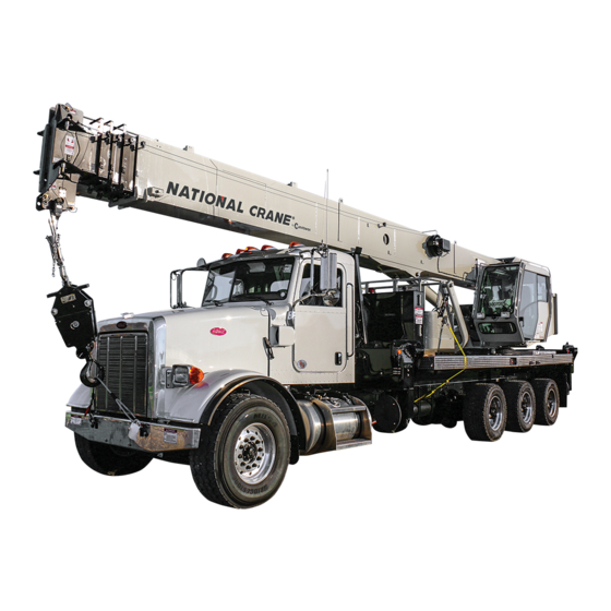
Manitowoc National Crane NBT40-1 Series Manuals
Manuals and User Guides for Manitowoc National Crane NBT40-1 Series. We have
3
Manitowoc National Crane NBT40-1 Series manuals available for free PDF download: Service Manual, Operator's Manual, Manual
Manitowoc National Crane NBT40-1 Series Operator's Manual (206 pages)
Brand:
Manitowoc
| Category:
Construction Equipment
| Size: 54.13 MB
Table of Contents
Table of Contents
5
Section 1
13
Supplemental Information
13
New Owner
13
Basic Nomenclature
13
Section 2
17
Safety Alert Symbol
18
Signal Words
18
General
18
Accidents
18
Operator Information
18
Operator Qualifications
19
Operational Aids
20
Rated Capacity Limiter (RCL) Systems (if Equipped)
20
Anti-Two-Blocking Device
20
Working Area Limiter (if Equipped)
21
Equipment Stability/Structural Strength
21
Load Charts
22
Work Site
22
Wind Forces
22
Wind Speeds
23
Lifting Operations
35
Counterweight
36
Outrigger Lift off
36
Multiple Equipment Lifts
36
Tilt-Up Panel Lifting
36
Pile Driving and Extracting
37
Crane Equipment
37
Equipment Inspection
37
Electrocution Hazard
38
Set-Up and Operation
39
Electrocution Hazard Devices
39
Electrical Contact
40
Special Operating Conditions and Equipment
40
Grounding the Crane
40
Personnel Handling
41
Environmental Protection
42
Maintenance
42
Service and Repairs
43
Lubrication
43
Tires
44
Hoist Rope
44
Sheaves
46
Batteries
46
Engine
46
Transporting Equipment
46
Travel Operation
47
Work Practices
48
Personal Considerations
48
Crane Access
48
Job Preparation
48
Working
48
Lifting
49
Hand Signals
50
Boom Extension
52
Parking and Securing
52
Shut-Down
52
Cold Weather Operation
52
Temperature Effects on Hook Blocks
53
Temperature Effects on Hydraulic Cylinders
53
Overload Inspection
54
Boom Inspection
56
Superstructure Inspection
58
Carrier Inspection
60
Section 3
63
General
63
Safety Alert Symbol
63
Signal Words
64
General
64
Accidents
64
Operator Information
64
Operator Qualifications
65
Operational Aids
66
Working Area Limiter (if Equipped)
66
Aerial Lift Stability/Structural Strength
66
Work Site
67
Wind Forces
67
Aerial Lift Operations
67
Boom Extension
69
Counterweight
69
Outrigger Lift off
69
Aerial Lift Inspection
69
Electrocution Hazard
70
Set-Up and Operation
70
Electrocution Hazard Devices
71
Electrical Contact
71
Special Operating Conditions and Aerial Lift
72
Grounding the Aerial Lift
72
Environmental Protection
72
Maintenance
72
Service and Repairs
73
Lubrication
74
Tires
74
Batteries
74
Engine
74
Work Practices
75
Personnel Considerations
75
Aerial Lift Access
75
Job Preparation
75
Working
75
Parking and Securing
77
Shut-Down
77
Transporting Aerial Lift
77
Travel Operation
77
Cold Weather Operation
78
Temperature Effects on Hydraulic Cylinders
78
Chassis Cab Controls
82
Chassis Cab Ignition Switch
82
Power Take off
82
Park Brake
82
Engine Speed Governor
82
Neutral Start/Safety Switch
82
Ground Controls
82
Crane Cab Controls
82
Outrigger Controls
82
Leveling of Equipment
86
Equipment Level Indicators
87
Swing Brake Pedal
89
Boom Telescope Pedal (if Equipped)
89
Foot Throttle Pedal
89
RCL Display
89
RCL and Minimum Wrap Bypass Switch
90
Hydraulic Oil Indicator
90
Main Hoist Minimum Wrap Indicator
90
Main Hoist Speed Switch
90
Hand Throttle Control
90
Emergency Stop Switch
91
Operator Cab/Ground Control Ignition Switch
91
Aux Hoist Speed (if Equipped)
91
Auxiliary Hoist Minimum Wrap Indicator
91
Ac/Heater Vent
91
Receptacle
91
Radio Remote/Aerial Power Switch (if Equipped)
91
Crane Control Power Switch
91
Hydraulic Tool Circuit Switch (if Equipped)
91
Cab Work Light Switch
91
Windshield Wiper Switch
92
Cab Climate Controls
92
360°Swinglock Pedal (if Equipped)
92
Boom Lift Control Lever
92
Hoist Control Lever
92
Hoist Rotation Indicator Display
92
Hoist Rotation Indicator
92
Telescope Control Lever
92
Warning Horn Button
92
Swing Control Lever
93
Seat Back Adjustment
93
Seat & Seat Frame Lever
93
Climate Control Unit
93
Swing Brake Switch
93
House Lock
93
Heater
93
Adjustable Swing Speed Valve
94
Operating Procedures
94
Crane Familiarization
94
Crane Cab Access
94
Crane Checks
94
Cold Weather Operation
95
Crane Warm-Up Procedures
95
Engine
95
Transmission
95
Hoist
95
Swing Drive and Turntable Bearing
96
Axles
96
Hydraulic Oil System
96
Anti-Two-Block (A2B) Check
96
RCL Check
96
Outrigger Setup
97
Leveling of the Crane
97
Equipment Level Indicators Adjustment
97
Setting the Outriggers
97
Outrigger Monitoring System (OMS)
98
Outrigger Jack Monitoring
98
Startup
99
Outrigger Setup
99
During Operation
99
Hoist System Operation
100
Hoist Two Speed Operation
100
Counterweight
100
Work Site Location
100
Before Leaving the Chassis Cab
100
Stowing and Parking
100
Unattended Equipment
101
Before Performing the Lift
101
Load Chart
101
Using the Load Chart
101
Lifting the Load
103
Shut down and Preparation for Road Travel
103
Section 5
105
Controls and Operating Procedures
105
Aerial Lift Controls
105
Power Take off
106
Outriggers
106
Outrigger Controls - Aerial Lift
106
Outrigger Monitoring System (OMS)
106
Outrigger Jack Monitoring System
106
Leveling of the Aerial Lift
106
Equipment Level Indicators
106
Equipment Ground Controls
106
Platform Controls
107
Radio Remote Controller
107
Aerial Functions
111
Activation of the Platform Controls
111
Emergency Lowering Procedure
112
Operational Procedure
113
Operator Presence Footswitch
115
Operator Feedback Screen
115
RCL Display
117
RCL Check
118
Radio Remote/Aerial Power Switch
118
Reach Diagram
118
Hydraulic Tool Circuit - Option
118
Equipment Familiarization
119
Hoist System Operation
119
Work Site Location
119
Before Leaving the Chassis Cab
119
Before Performing the Aerial Lift
119
Pre-Use Inspection
119
Function Check
120
Cold Weather Operation
120
Equipment Warm-Up Procedures
120
Stowing and Parking
120
Unattended Equipment
121
Preparation for Job-Site Travel
121
Shut down and Preparation for Road Travel
122
Section 6
123
Jib Safety Information
123
Jib Operation
124
Deployment Procedure
124
Stowing Procedure
125
Jib Removal
127
Jib Maintenance
127
Rope Installation-Hoist
128
Synthetic Rope
128
Wire Rope
128
Multi-Part Lines
128
Wedge Sockets
129
Terminator Wedge Installation
129
Wedge Socket Installation
129
Dead-End Rigging
130
Hoist Rope Tie down
131
Hoist Rope Tie down - Boom Mounted Hoist
131
Stow Pegs for Hoist Rope
133
A2-B Weight Installation and Stowage
133
Wire Rope
133
Synthetic Rope
133
Aerial Lift Platform
134
Aerial Lift Platform Installation
136
Platform Mounting
136
Platform Quick Attachment
137
Platform Mounting and Installation
139
Platform Operation
139
Platform Brake Operation
139
Hydraulic Tool Connection - Optional
140
Safety Harness
140
Section 7
141
Lubricants
141
Arctic Conditions below -9°C (15°F)
142
Chassis Grease
142
Low Temperature Grease
142
Extreme Pressure Multipurpose Gear Lubricant (EPGL)
142
Open Gear Lubricant
142
Antifreeze/Coolant (for Cab Heater)
142
Anti-Wear Additives
142
Hydraulic Oil
142
Lubricants
142
Standard Hydraulic Oil
143
Arctic Hydraulic Oil
143
Hydraulic Oil Inspection
143
Lubrication
143
Boom Lubrication
147
Internal Cable Sheave Lubrication
147
Side and Bottom Boom Wear Pad Lubrication
147
Top Boom Wear Pad Lubrication
147
Outrigger Beam Lubrication
147
Hoist Brake Oil
148
Hoist Gearbox Oil
148
Swing Gearbox and Brake Oil
149
Hydraulic Oil Reservoir Level
149
Air Conditioning
150
Wire Rope Lubrication
150
Aerial Lift Platform Lubrication
151
Carwell® Rust Inhibitor
152
Protecting Cranes from Rusting
152
Cleaning Procedures
152
Inspection and Repair
153
Application
153
Areas of Application
154
Section 8
157
Inspection and Maintenance
157
General Inspections
157
Special Boom Inspection
159
Stability
159
Hoist Rope Inspection and Maintenance
159
Keeping Records
159
Environmental Conditions
159
Dynamic Shock Loads
160
Precautions and Recommendations During Inspection
160
Inspection
160
Wire Rope Replacement
161
Care of Wire Rope
161
Replacement Cable
161
Equipment Adjustments and Repairs
162
Boom Extension Cable
162
Jib Jack Service and Maintenance
162
Lubrication
162
Rust Prevention
162
Hydraulic System
162
Oil Cooler
162
Hydraulic System Trouble Diagnosis
162
Section 9
167
Inspection and Maintenance
167
General Inspections
167
Pre-Start or Frequent Inspections
168
Pre-Start Functional Test
168
Periodic Inspection and Test
168
Inspections
168
Section 10
171
Tire Load and Inflation Table
173
Specifications
176
Pto
176
Hydraulic
176
Hydraulic Reservoir
176
Hydraulic Intensifier Valve - Optional
176
Air Conditioner
176
Hoist System
176
Equipment Operating Speeds
177
Counterweight
177
General
178
Boom Weight - Including Hoist/Rope
178
Multiple Part Line Reeving
178
Section 11
181
General
181
Capacity Chart
181
Safety Information
181
Advertisement
Manitowoc National Crane NBT40-1 Series Service Manual (238 pages)
Brand:
Manitowoc
| Category:
Construction Equipment
| Size: 11.3 MB
Table of Contents
Section 2 Hydraulic System 2
37
Table of Contents
37
Parts Replacement
40
Draining and Flushing
40
Hydraulic Oil Recommendations
40
Service
40
Maintenance
40
Welding Precautions
40
Label Parts When Disassembling
40
Hydraulic System Maintenance Precautions
40
General
40
Removing Air from the Hydraulic System
41
Directional Control Valve (DCV)
42
Hydraulic Pump
42
System Description
42
RCL Lockout Manifold
43
Swing and Air Conditioning Control Valve
43
Hydraulic Reservoir with Filter
43
Hydraulic Remote Controllers (HRC)
43
Pilot Manifold
43
Radio Remote Manifold (Optional)
43
Tool Circuit Manifold (Optional)
43
Pressure Intensifier Manifold (Optional)
43
Pump Manifold
43
Outrigger Control Manifolds
43
Hydraulic Oil Cooler
44
Hydraulic Valves
44
Maintenance
49
Relief Valve Pressure Setting Procedures
49
Description
49
System Pressure Check
51
Hydraulic Reservoir and Filter
53
Hydraulic Filter Replacement
54
Hydraulic Oil Cooler
55
Hydraulic Oil Cooler Service & Maintenance
55
Hydraulic Valves
55
Directional Control Valve (DCV)
56
Swing Gearbox
57
Crane Function Power Switch
57
Holding Valves
57
Outrigger Manifolds
57
Hydraulic Remote Controllers
57
Hydraulic Pump
58
Description
58
Removal
58
Installation
58
Pump Startup
58
Pump Margin Pressure Setting
59
Maximum Pump Pressure Setting
59
Load Sense Relief Valve Pressure Setting
59
Troubleshooting
60
Caution
65
Dielectric Grease
66
Connector Troubleshooting
67
General Troubleshooting
67
Ignition Switch
67
RCL and A2B System Description
67
RCL System Description
67
Tooling for Troubleshooting
67
Troubleshooting the Electrical Swivel
67
Fuse and Relay Panel
68
Micro Relay Fuse Box 2
70
Micro Relay Fuse Box 3
70
Micro Relay Fuse Box 4
71
VEC Module
73
Crane Manifold Solenoids
74
Front Outrigger Manifold
76
Outrigger Manifolds
76
Rear Outrigger Manifold
77
Hydraulic Oil Cooler
78
Hydraulic Temperature Sensor Warning Light
78
Outrigger Jack Monitoring System (Optional)
78
Outrigger Monitoring System (OMS)
78
Four-Section Boom
79
Boom Removal
80
Four-Section Boom Disassembly
81
Additional Maintenance (Disassembled Boom)
88
Four-Section Cable Tensioning
95
Cable Retention
96
Four-Section Top and Bottom Pad Replacement (Assembled Boom)
97
Five-Section Boom
100
Boom Removal
101
Five-Section Boom Disassembly
102
Additional Maintenance (Disassembled Boom)
112
Five-Section Boom Assembly
112
Five-Section Cable Tensioning
119
Cable Retention
121
Five-Section Top and Bottom Pad Replacement (Assembled Boom)
122
Boom Calibration
123
Inner Side Wear Pads
124
Rear, Bottom Wear Pads
125
Hydraulic Cylinder
126
Cylinder Reassembly
127
Jib Boom
128
Jib Stowage Bracket Adjustment
128
Jib Jack Service and Maintenance
130
National Crane
133
Hoist Installation
134
Hoist Removal
134
Hoist Rotation Indicator (HRI) System
136
Drum Rotation Indicator
137
Removal
137
Programming the 3Rd Wrap Indicator
138
Shipping Mode (Series a Only)
139
Assembly
140
Disassembly
140
For Series "A
140
Hoist Repair
140
Series "B" Circuit Breaker Reset Instructions
140
Troubleshooting
140
Brake
144
Motor
145
Planetary Set
145
Troubleshooting
146
Description Theory of Operation 6
147
Disassembly
150
Disassembly and Assembly Instructions
150
Parts Required to Rebuild
150
Removal and Installation
150
Swing Gearbox and Brake
150
Tools Required
150
Case Assembly Repair
151
Input Planetary Repair
151
Output Planetary Repair
151
Shaft Repair
151
Unit Assembly
151
Disassembly
152
Swing Brake
152
Assembly
154
Description
154
General
154
Maintenance
154
Swing Bearing
154
Torquing Swing Bearing Capscrews
154
Swing Bearing Capscrews
155
Tools Required
155
Bearing Clearance
157
Bearing Replacement
158
Removal
158
Installation
159
Slew Potentiometer Adjustment
160
Slew Sensor Calibration
160
Installation
162
Removal
162
Swing Lock
162
Testing
162
House Lock
164
Installation
164
Removal
164
Section 7 Outriggers
165
Description
167
Outrigger Beam Assembly
168
Removal
168
Assembly
169
Cable Tensioning
170
Outrigger Calibration
170
Side Pads
170
Outrigger Jack Monitoring System (Optional)
173
Outrigger Monitoring System (OMS)
173
String Potentiometer
173
Section 8 Lubrication
175
Anti-Wear Additives
176
Antifreeze/Coolant (for Cab Heater)
176
Arctic Conditions below -9°C (15°F)
176
Chassis Grease
176
Hydraulic Oil
176
Low Temperature Grease
176
Lubricants
176
Multipurpose Extreme-Pressure Gear Lubricant
176
Open Gear Lubricant
176
Standard Hydraulic Oil
176
Arctic Hydraulic Oil
177
Hydraulic Oil Inspection
177
Hoist Brake Oil
182
Internal Cable Sheave Lubrication
182
Lubrication
182
Outrigger Beam Lubrication
182
Side and Bottom Boom Wear Pad Lubrication
182
Top Boom Wear Pad Lubrication
182
Hoist Gearbox Oil
183
Hydraulic Oil Reservoir Level
184
Swing Gearbox and Brake Oil
184
Air Conditioning
185
Wire Rope Lubrication
185
Carwell® Rust Inhibitor
186
Cleaning Procedures
186
Protecting Cranes from Rusting
186
Application
187
Inspection and Repair
187
Areas of Application
188
Section 9 Crane Installation
191
Minimum Truck Requirements
192
Mounting Configurations
194
NBT36-1 Configuration - Standard Torsion Box and 103 Ft Boom
194
NBT36-1 Configuration - Standard Torsion Box and 127 Ft Boom
195
NBT40-1 Configuration - Standard Torsion Box and 103 Ft Boom
196
NBT40-1 Configuration - Standard Torsion Box and 127 Ft Boom
197
NBT40-1 Configuration - Standard Torsion Box and 142 Ft Boom
198
NBT40-1 Configuration - Extended Torsion Box and 127 Ft Boom
199
NBT40-1 Configuration - Extended Torsion Box and 142 Ft Boom
200
NBT45-1 Configuration - Extended Torsion Box and 127 Ft Boom
201
NBT45-1 Configuration - Extended Torsion Box and 142 Ft Boom
202
NBT45-1 Configuration - Extended Torsion Box and 161 Ft Boom
203
Direct PTO Mount
204
Horsepower
204
PTO Ratio
204
PTO Requirements
204
Pump Rotation
204
Truck Frame Strength
205
Section Modulus Tables
206
Positioning the Crane on the Truck
211
PTO, Pump, and Reservoir
211
Truck Preparation
211
Welding Precautions
211
Reinforcement After-Frame Extension
212
Mounting the Crane
215
Truck Interface Electrical Connection
219
Hydraulic Pump Connection
221
Initial Crane Run-In Procedure
223
RCL Calibration
223
Stability Test
223
Counterweight
225
Counterweight Installation
226
Counterweight Removal
226
Air Conditioner
228
Hoist System
228
Hydraulic
228
Hydraulic Intensifier Valve - Optional
228
Hydraulic Reservoir
228
Pto
228
Specifications
228
Counterweight
229
Boom Weight - Including Hoist/Rope
230
General
230
Dimensional Drawing
231
NBT40-1 and NBT45-1 Extended T-Box
231
NBT40-1 and NBT45-1 Standard T-Box
232
NBT36-1 Extended T-Box
233
Manitowoc National Crane NBT40-1 Series Manual (17 pages)
LOAD CHARTS & REACH DIAGRAM
Brand:
Manitowoc
| Category:
Construction Equipment
| Size: 0.27 MB
Advertisement
Advertisement
Related Products
Manitowoc National Crane NBT45-1
Manitowoc National Crane NBT40 Series
Manitowoc National Crane NBT45
Manitowoc National Crane NBT50 Series
Manitowoc National Crane NBT60L
Manitowoc National Crane NBT36-1
Manitowoc National Crane NBT36
Manitowoc National Crane NBT30H-2
Manitowoc National Crane NBT50L Series
Manitowoc NBT55L
Manitowoc Categories
Construction Equipment
Ice Maker
Accessories
Commercial Food Equipment
Dispenser
More Manitowoc Manuals
Login
Sign In
OR
Sign in with Facebook
Sign in with Google
Upload manual
Upload from disk
Upload from URL