Table of Contents
Advertisement
Quick Links
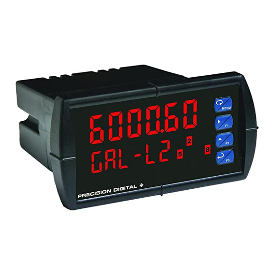
™ PD6000 Analog Input Process Meter
P
V
RO
U
Instruction Manual
•
1/8 DIN Digital Panel Meter with NEMA 4X, IP65 Front
•
0-20 mA, 4-20 mA, 0-5 V, 1-5 V, and ±10 V Field Selectable Inputs
•
Dual-Line 6-Digit Display, 0.6" (15 mm) & 0.46" (12 mm)
•
Isolated 24 VDC @ 200 mA Transmitter Power Supply
•
2 or 4 Relays with Interlocking Capability + Isolated 4-20 mA Output Options
•
Free PC-Based, On-Board, MeterView Pro USB Programming Software
•
No Assembly Required
•
Optional SunBright Display Models for Outdoor Applications
•
Operating Temperature Range: -40 to 65°C (-40 to 149°F)
•
UL & C-UL Listed. E160849; 508 Industrial Control Equipment
•
Input Power Options: 85-265 VAC / 90-265 VDC or 12-24 VDC / 12-24 VAC
•
Display Input in Two Different Scales - Great for Level Applications
•
Multi-Pump Alternation Control
•
Round Horizontal Tank Function; Just Enter Diameter & Length
•
32-Point Linearization, Square Root Extraction and Programable Exponent Function
•
Programmable Display, Function Keys & Digital Input
•
External 4-Relay & Digital I/O Expansion Modules
•
RS-232 & RS-485 Serial Communication Options with Modbus RTU
•
Password Protection
•
Wide Assortment of NEMA 4X Enclosures for up to Ten Meters
•
Light / Horn & Reset Button Accessory
•
Control Station Accessory for Remote Operation of P
•
3-Year Warranty
PRECISION DIGITAL CORPORATION
233 South Street • Hopkinton MA 01748 USA
Tel (800) 343-1001 • Fax (508) 655-8990
www.predig.com
MeterView Pro
USB Install
V
RO
U
Advertisement
Table of Contents
Troubleshooting

Related Manuals for Precision Digital Corporation ProVu Series


Summary of Contents for Precision Digital Corporation ProVu Series
- Page 1 Wide Assortment of NEMA 4X Enclosures for up to Ten Meters • Light / Horn & Reset Button Accessory • Control Station Accessory for Remote Operation of P • 3-Year Warranty PRECISION DIGITAL CORPORATION 233 South Street • Hopkinton MA 01748 USA Tel (800) 343-1001 • Fax (508) 655-8990 www.predig.com...
- Page 2 – do not use a different cable. DO NOT apply Limited Warranty AC or DC power to the meter while your PC is Precision Digital Corporation warrants this connected to the meter as it will disrupt the USB connection. You don’t even have to apply an input...
-
Page 3: Table Of Contents
™ PD6000 Analog Input Process Meter Instruction Manual Table of Contents Introduction ......................6 Ordering Information ................... 6 Specifications....................... 7 General ......................7 Process Input ....................8 Relays ....................... 8 Isolated 4-20 mA Transmitter Output ............9 USB Connection ....................9 On-Board Digital Input (F4) ................ - Page 4 ™ PD6000 Analog Input Process Meter Instruction Manual Pump Alternation Control Operation ............28 Relay Sampling Operation ................28 Relay Operation Details ................29 Overview ..................... 29 Relays Auto Initialization ................29 Fail-Safe Operation ..................29 Front Panel LEDs ..................29 Latching and Non-Latching Relay Operation ..........
- Page 5 ™ PD6000 Analog Input Process Meter Instruction Manual Table of Figures Figure 1. 1/8 DIN Panel Cutout Dimensions ............ 11 Figure 2. Panel Mounting Details ..............11 Figure 3. Meter Dimensions - Side View ............11 Figure 4. Meter Dimensions - Top View ............11 Figure 5.
-
Page 6: Introduction
™ PD6000 Analog Input Process Meter Instruction Manual Introduction Ordering Information Front, back and in between, the P meter boasts Standard Models specifications, features and functionality that make it 85-265 VAC 12-24 VDC Options Installed the only 1/8 DIN process meter you will ever need. Model Model The number one feature that makes the P... -
Page 7: Specifications
™ PD6000 Analog Input Process Meter Instruction Manual Specifications Overvoltage Installation Overvoltage Category II: Category Local level with smaller transient overvoltages than Installation Overvoltage Except where noted all specifications apply to Category III. operation at +25°C. Environmental Operating temperature range: General -40 to 65°C (-40 to 149°F) Storage temperature range:... -
Page 8: Process Input
™ PD6000 Analog Input Process Meter Instruction Manual Process Input Relays Inputs Field selectable: 0-20 mA, 4-20 mA Rating 2 or 4 SPDT (Form C) internal and/or 10 V (0-5 V, 1-5 V, 0-10 V) 4 SPST (Form A) external; rated 3 A Modbus PV (Slave) @ 30 VDC and 125/250 VAC resistive load;... -
Page 9: Isolated 4-20 Ma Transmitter Output
™ PD6000 Analog Input Process Meter Instruction Manual ® Isolated 4-20 mA Transmitter Modbus RTU Serial Output Communications Output Process variable (PV), max, min, set points 1 – 247 (Meter address) Slave Id Source 1-8, Modbus input, or manual control mode 300 –... -
Page 10: Compliance Information
™ PD6000 Analog Input Process Meter Instruction Manual Compliance Information Safety Information Safety • Read complete instructions prior to installation UL & C-UL Listed USA & Canada and operation of the meter. UL 508 Industrial Control Equipment UL File Number E160849 Front Panel UL Type 4X, NEMA 4X, IP65;... -
Page 11: Panel Mounting Instructions
™ PD6000 Analog Input Process Meter Instruction Manual Mounting Dimensions Panel Mounting Instructions • Prepare a standard 1/8 DIN panel cutout - 3.622" x 1.772" (92 mm x 45 mm). Refer to Figure 1. 1/8 DIN Panel Cutout Dimensions below for more details. •... -
Page 12: Installation Overview
™ PD6000 Analog Input Process Meter Instruction Manual Once the driver is installed, an AutoPlay Installation Overview dialog should appear for the drive We recommend the following sequence for getting the “MAINSTAL.” Click “Open folder to view meter into service: files.”... -
Page 13: Transmitter Supply Voltage Selection (P+, P-)
™ PD6000 Analog Input Process Meter Instruction Manual Transmitter Supply Voltage RELAY2 RELAY1 Selection (P+, P-) All meters, including models equipped with the 12-24 VDC power option, are shipped from the SIGNAL factory configured to provide 24 VDC power for 1 2 3 4 5 6 7 8 the transmitter or sensor. -
Page 14: Power Connections
™ PD6000 Analog Input Process Meter Instruction Manual Power Connections The current input is protected against current overload by a resettable fuse. The display may or Power connections are made to a two-terminal may not show a fault condition depending on the connector labeled POWER. -
Page 15: Switching Inductive Loads
™ PD6000 Analog Input Process Meter Instruction Manual Switching Inductive Loads F4 Digital Input Connections The use of snubbers to suppress electrical noise is A digital input, F4, is standard on the meter. This strongly recommended when switching inductive digital input should be connected with a normally loads to prevent disrupting the microprocessor’s open contact across F4 and COM, or with an active operation. -
Page 16: External Relays & Digital I/O Connections
™ PD6000 Analog Input Process Meter Instruction Manual External Relays & Digital I/O Interlock Relay Feature Connections As the name implies, the interlock relay feature reassigns one, or more, alarm/control relays for use The relay and the digital I/O expansion modules as interlock relay(s). -
Page 17: Setup And Programming
™ PD6000 Analog Input Process Meter Instruction Manual Setup and Programming Front Panel Buttons and Status LED Indicators There is no need to recalibrate the meter when first received from the factory. The meter is factory calibrated prior to shipment for milliamps and volts with calibration equipment that is certified to NIST standards. -
Page 18: Display Functions & Messages
™ PD6000 Analog Input Process Meter Instruction Manual Display Functions & Messages Display Functions & Messages The meter displays various functions and messages Display Parameter Action/Setting during setup, programming, and operation. The Description following table shows the main menu functions and Auto Automatic Set relay for automatic... -
Page 19: Main Menu
™ PD6000 Analog Input Process Meter Instruction Manual Main Menu Display Functions & Messages Display Parameter Action/Setting The main menu consists of the most commonly used Description functions: Setup, Reset, Control, and Password. • Press Menu button to enter Programming Mode Out 1 Output 1 Program output 1 value... -
Page 20: Setting Numeric Values
™ PD6000 Analog Input Process Meter Instruction Manual Setting the Input Signal (Input) Setting Numeric Values Enter the Input menu to set up the meter to display The numeric values are set using the Right and Up current (nmA) or voltage (Volt) inputs. arrow buttons. -
Page 21: Setting The Display Units Or Custom Tags (Units)
™ PD6000 Analog Input Process Meter Instruction Manual Setting the Decimal Point (dEc pt) Setting the Display Units or Custom Tags (units) The decimal point may be set with up to five decimal places or with no decimal point at all. Enter the display unit or custom tag that will be The decimal point selection should be made prior to displayed if d unit is selected as the line 2... -
Page 22: Programming The Meter (Prog)
™ PD6000 Analog Input Process Meter Instruction Manual Programming the Meter (prog) Scaling the Meter (SCALE) The process input (4-20 mA, 10 VDC) can be scaled The meter may either be scaled (SCALE) without to display the process variable in engineering units. applying an input or calibrated (Cal) by applying an A signal source is not needed to scale the meter;... - Page 23 ™ PD6000 Analog Input Process Meter Instruction Manual Error Message (Error) Calibrating the Meter with External An error message indicates that the calibration or Source (Cal) scaling process was not successful. Note: To scale the meter without a signal source After the error message is displayed, the meter refer to Scaling the Meter (SCALE) on page 22.
-
Page 24: Setting The Display Parameter & Intensity (Dsplay)
™ PD6000 Analog Input Process Meter Instruction Manual Setting the Display Parameter & Display Parameter Menu Intensity (dsplay) The main display (Line 1) can be programmed to display: Process value 1 (PV1) Process value 2 (PV2)* Percent of PV1 (PCT)* Relay set points Max &... -
Page 25: Setting The Relay Operation (Relay)
™ PD6000 Analog Input Process Meter Instruction Manual Setting the Relay Action Setting the Relay Operation Operation of the relays is programmed in the Action (relay) menu. The relays may be set up for any of the This menu is used to set up the operation of the following modes of operation: relays. -
Page 26: Programming Set And Reset Points
™ PD6000 Analog Input Process Meter Instruction Manual Programming Set and Reset The following graph shows the loop break relay operation for a high alarm relay. Points High alarm indication: program set point above reset point. Low alarm indication: program set point below reset point. -
Page 27: Low Alarm Operation (Set < Reset)
™ PD6000 Analog Input Process Meter Instruction Manual Low Alarm Operation (Set < Reset) Low Alarm with Fail-Safe Operation (Set < Reset) For Manual reset mode, ACK can be pressed anytime to turn "off" relay. For relay to turn back “on”, signal must go above set point and then go below it. Note: Relay coil is energized in non-alarm condition. -
Page 28: Pump Alternation Control Operation
™ PD6000 Analog Input Process Meter Instruction Manual Pump Alternation Control Operation Relay Sampling Operation When the signal crosses the set point, the relay trips and the sample time starts. After the sample time has elapsed, the relay resets. The cycle repeats every time the set point is crossed, going up for high alarms and going down for low alarms. -
Page 29: Relay Operation Details
™ PD6000 Analog Input Process Meter Instruction Manual Front Panel LEDs Relay Operation Details The LEDs on the front panel provide status indication Overview for the following: The relay capabilities of the meter expand its Status Status usefulness beyond simple indication to provide users Alarm 1 Alarm 5 with alarm and control functions. -
Page 30: Non-Latching Relay (Auto)
™ PD6000 Analog Input Process Meter Instruction Manual Non-Latching Relay (Auto) Latching Relay with Clear (Lt-Clr) In this application, the meter is set up for automatic In this application, the meter is set up for manual reset (non-latching relay). Acknowledging the alarm reset only after the signal passes the reset point while it is still present has no effect on either the LED (alarm condition has cleared). -
Page 31: Acknowledging Relays
™ PD6000 Analog Input Process Meter Instruction Manual Acknowledging Relays Application #1: Pump Alternation Using Relays 1 & 2 There are three ways to acknowledge relays Relays 1 and 2 are set up for pump alternation. programmed for manual reset: Relays 3 and 4 are set up for low and high alarm Via the programmable front panel function keys indication. -
Page 32: Setting Up The Interlock Relay (Force On) Feature
™ PD6000 Analog Input Process Meter Instruction Manual The following graphics provide a visual representation Setting Up the Interlock Relay of a typical pump alternation application with high and (Force On) Feature low alarm monitoring: Relays 1-4 can be set up as interlock relays. To set up the relays for the interlock feature: Relay #4 turns the main pump on at 6000 gallons 1. -
Page 33: Scaling The 4-20 Ma Analog Output (Aout)
™ PD6000 Analog Input Process Meter Instruction Manual Scaling the 4-20 mA Analog Reset Menu (reset) Output (Aout) The Reset menu is used to reset the maximum or minimum reading (peak or valley) reached by the The 4-20 mA analog output can be scaled to provide process;... -
Page 34: Setting Up The Password (Pass)
™ PD6000 Analog Input Process Meter Instruction Manual Disabling Password Protection Setting Up the Password (pass) To disable the password protection, access the The Password menu is used for programming three Password menu and enter the correct password levels of security to prevent unauthorized changes to twice, as shown below. -
Page 35: Advanced Features Menu
™ PD6000 Analog Input Process Meter Instruction Manual Advanced Features Menu Advanced Features Menu & Display Messages To simplify the setup process, functions not needed Display Parameter Action/Setting for most applications are located in the Advanced No PtS Number of Set PV1 for 2 to 32-point Features menu. -
Page 36: Noise Filter (Filter)
™ PD6000 Analog Input Process Meter Instruction Manual Rounding Feature (round) Advanced Features Menu & Display Messages The rounding feature is used to give the user a Display Parameter Action/Setting steadier display with fluctuating signals. Rounding is Assign digital output 1 – 8, dO 1 Digital output 1 used in addition to the filter function. -
Page 37: Select Menu (Select)
™ PD6000 Analog Input Process Meter Instruction Manual Select Menu (SElect) Multi-Point Linearization (Linear) Meters are set up at the factory for linear function with The Select menu is used to select the input signal 2-point linearization. Up to 32 linearization points can conditioner applied be selected for PV1 under the linear function. -
Page 38: Low-Flow Cutoff (Cutoff)
™ PD6000 Analog Input Process Meter Instruction Manual Changing the Volume from Gallons to Liters Analog Output Source The source for generating the 4-20 mA output may be In the above graphic, entering the 48" for the diameter assigned to the process variable, maximum or and 120"... -
Page 39: Programmable Function Keys User Menu (User)
™ PD6000 Analog Input Process Meter Instruction Manual Programmable Function Keys Function Keys & Digital I/O Available Settings User Menu (user) Display Description The User menu allows the user to assign the front Ln1 Lo Display minimum display value on line 1 panel function keys F1, F2, and F3, the digital input Ln1 HL Display maximum &... -
Page 40: Internal Source Calibration (Ical)
™ PD6000 Analog Input Process Meter Instruction Manual Internal Source Calibration (ICAL) The meter is factory calibrated prior to shipment for milliamps and volts with calibration equipment that is certified to NIST standards. The use of calibrated signal sources is necessary to calibrate the internal source of the meter. -
Page 41: Meter Operation
™ PD6000 Analog Input Process Meter Instruction Manual Meter Operation F4 Operation A digital input, F4, is standard on the meter. This The meter is capable of accepting current (0-20 mA, digital input is programmed identically to function keys 4-20 mA) and voltage signals (0-5 V, 1-5 V, 0-10 V, F1, F2, and F3. -
Page 42: Troubleshooting
™ PD6000 Analog Input Process Meter Instruction Manual Troubleshooting Reset Meter to Factory Defaults When the parameters have been changed in a way The rugged design and the user-friendly interface of that is difficult to determine what’s happening, it might the meter should make it unusual for the installer or be better to start the setup process from the factory operator to refer to this section of the manual. -
Page 43: Factory Defaults & User Settings
™ PD6000 Analog Input Process Meter Instruction Manual Factory Defaults & User Settings Parameter Display Default Setting The following table shows the factory setting for most On delay relay 3 On 3 0.0 sec of the programmable parameters on the meter. Off 3 Off delay relay 3 0.0 sec... -
Page 44: Troubleshooting Tips
™ PD6000 Analog Input Process Meter Instruction Manual Troubleshooting Tips This meter is a highly sophisticated instrument with an extensive list of features and capabilities. If the front panel buttons are used to program the meter, it may be a difficult task to keep everything straight. That is why we strongly recommend the use of the free MeterView Pro software for all programming activities. -
Page 45: Eu Declaration Of Conformity
EN 55022:2010, EN 61000-6-2:2005, EN 61010-1:2010, and EN 61326:2013 and there were no major technical changes affecting the latest technical knowledge for the products listed above. Product Markings: Signed for and on behalf of Precision Digital Corporation: Name: Jeffrey Peters Company:... - Page 46 Email: sales@predig.com Place Orders Email: orders@predig.com For the latest version of this manual please visit www.predig.com PRECISION DIGITAL CORPORATION 233 South Street • Hopkinton MA 01748 USA Tel (800) 343-1001 • Fax (508) 655-8990 www.predig.com LIM6000_N SFT039 Ver 4.010 & up...
Need help?
Do you have a question about the ProVu Series and is the answer not in the manual?
Questions and answers