Advertisement
Quick Links
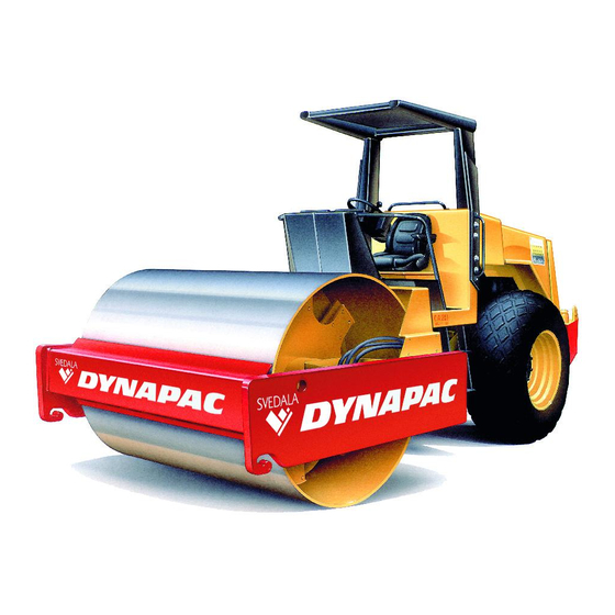
The CA 25/30 family of vibratory rollers
consists of the CA 251 Standard, Drum Drive
(D) and Pads+Drum Drive (PD) together with
CA 301 Std., D and PD.
These rollers are designed for the compaction
of roads, airfields, dams and similar
constructions.
The CA 251A compacts asphalt, concrete,
base courses and subbase courses efficiently
and at a high rate.
Printed in Sweden
We reserve the right to change specifications without notice
CA 251/301 M251EN2
MAINTENANCE
CA 251/301
VIBRATION ROLLER
M251EN2, December 1996
Diesel engine:
Deutz F6L 912
Cummins 6BT 5.9
The instructions apply from
CA 251:
PIN (S/N) *58310256*
CA 301:
PIN (S/N) *59010306*
CA 251A: PIN (S/N) *58310414*
Box 504 • SE-371 23 KARLSKRONA • Sweden
Tel. +46 455 627 00 • Telex 43041 dynkar s
Telecopier +46 455 627 30
1
Advertisement


Need help?
Do you have a question about the CA 251 and is the answer not in the manual?
Questions and answers