
Related Manuals for Dynapac CA280D


Summary of Contents for Dynapac CA280D
- Page 1 DYNAPAC CA280 OPERATION O280EN1 Box 504, SE-371 23 Karlskrona, Sweden Phone: +46 455 30 60 00, Fax: +46 455 30 60 30 www.dynapac.com...
- Page 2 ILF015WO1...
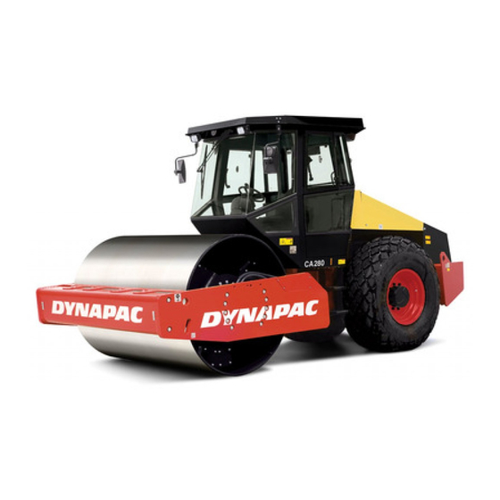
- Page 3 CA280 PIN (S/N) *68820280* CA280D PIN (S/N) *68920280* One of Dynapac's medium heavy vibratory soil compactors is the CA280. It is available in a solely wheel-driven version and in a wheel-and-drum-driven version, called CA280D. All types of base courses and reinforcement courses can be compacted to considerable depth.
-
Page 4: Table Of Contents
CONTENTS Page Safety instructions (Read the Safety Manual also) ..3 Safety when driving ............4 Safety decals, location/description ....... 5, 6 Machine and engine plates ........... 7, 8 Instruments and controls ..........9 Instruments and controls, functional description ..10, 11 Controls in the cab ............ -
Page 5: Safety Instructions (Read The Safety Manual Also)
17. Make no changes or modifications on the roller that could affect safety. Changes may only be made following written consent by Dynapac. 18. Do not use the roller until the hydraulic fluid has reached its normal work- ing temperature. -
Page 6: Safety When Driving
SAFETY WHEN DRIVING Driving near an edge When you drive near an edge, at least two thirds of the drum width must be on solid ground. Remember that the machine’s center of gravity is displaced outward when you steer to one side. For example, it shifts to the right when you steer to the left. -
Page 7: Safety Decals, Location/Description
SAFETY DECALS, LOCATION/DESCRIPTION CA280 O280EN1... - Page 8 SAFETY DECALS, LOCATION/DESCRIPTION 791279 Sound Power Crush zone, articulation/ The operator is urgently level Drum. Maintain a safe requested to read the safety distance from the crush manual, and the operation zone. and maintenance instructions before using the machine. Diesel fuel Warning - rotating engine The articulation must be components.
-
Page 9: Machine And Engine Plates
MACHINE AND ENGINE PLATES Machine plate The machine type plate (1) is affixed on the front left edge of the tractor frame. The plate shows the manufacturer's name and address, type of machine and PIN "Part Identification Number" (serial number). Please state the PIN (serial number) of the roller when ordering spare parts. - Page 10 MACHINE AND ENGINE PLATES Engine plate The engine data plate (1) is affixed to the right side of the engine under the injection pump. The plate indicates the type of engine, serial number and engine data. Please state the engine serial number when ordering spare parts.
-
Page 11: Instruments And Controls
INSTRUMENTS AND CONTROLS Fig. 7 Instruments and control panel 1. Horn 12. Warning lamp, hydraulic temperature 2. Starter switch/Preheating lamp 13. Amplitude selector Low/0/High 3. Hazard beacon 14. Speed selector, drum 4. Working lights 15. Speed selector, rear axle 5. Reserve/Parking brake knob 16. -
Page 12: Instruments And Controls, Functional Description
INSTRUMENTS AND CONTROLS, FUNCTIONAL DESCRIPTION Item in Designation Symbol Function fig. 7 Horn, switch Press to sound the horn. Starter switch In mode the electric circuit is broken. In mode all instruments and electric controls are powered, and the engine preheater is activated. - Page 13 INSTRUMENTS AND CONTROLS, FUNCTIONAL DESCRIPTION Item in Designation Symbol Function fig. 7 Left mode gives low amplitude. Amplitude selector Right mode gives high amplitude. Vibration switched OFF in O mode. Transport speed (High) Speed selector, drum (Optional) Working speed (Low) Transport speed (High) Speed selector, rear axle (Optional)
-
Page 14: Controls In The Cab
CONTROLS IN THE CAB Fig. 8b Cab roof, rear Fig. 8a Cab roof, front Fig. 8c Cab, right side Fig. 8d Cab, rear Fig. 8e Cab, left side CA280 O280EN1... -
Page 15: Controls In The Cab, Functional Description
CONTROLS IN THE CAB, FUNCTIONAL DESCRIPTION Items in Designation Symbol Function fig. 8 Wiper front, switch Press to turn on the front wiper. Wiper rear, switch Press to turn on the rear wiper. Screenwash front and rear Press at the top to spray the windscreen. panes, switch Press at the bottom to spray the rear screen. -
Page 16: Before Starting
BEFORE STARTING Battery disconnecter – Switching ON Remember to carry out daily service. See maintenance manual. The battery disconnecter is located in the engine compartment. Open the engine cover and set the key (1) to the ON position. The entire roller will be powered. The hourmeter (2) records the number of hours so long as the engine is running. - Page 17 BEFORE STARTING Instruments and lamps – Checking Turn the starter switch (2) to position I. Press the button (21) and make sure that all the control lamps light. Check that the fuel gauge (17) gives a reading. Check that the warning lamps for charging (7), oil pressure (12) and parking brake (8) light.
- Page 18 BEFORE STARTING Field of view Before starting, make sure that the field of view is unobstructed, both in front and behind. All cab windows must be clean and rearview mirrors properly adjusted. Fig. 15 Field of view CA280 O280EN1...
-
Page 19: Starting
STARTING Starting the engine Set the forward/reverse lever (20) in neutral. The engine can only be started with the lever in neutral. Set the amplitude selector (13) for Low/High vibration to mode O. Set the revs control (16) to the idling mode. Turn the starter switch (2) to mode I. -
Page 20: Driving
DRIVING Driving the roller Under no circumstances may the machine be operated from the outside. The operator must remain seated inside the machine during all operation. Move the revs control lever (16) upwards and latch it at its limit, engine speed should now be about 2300 rpm. Ensure that the steering is working properly by turning the steering wheel once to the right and once to the left while the roller is stationary. -
Page 21: Vibration/Driving
VIBRATION/DRIVING Low/High amplitude – Setting Drum vibration can be set in two modes, selected using the switch (13). Turn the knob to the left mode for low amplitude, to the right mode for high amplitude. Never alter the amplitude setting while the vibration is running. -
Page 22: Braking
BRAKING Using the reserve brake Braking is normally done with the forward/reverse lever (20). The hydrostatic transmission brakes the roller when the lever is moved toward neutral. In addition, multi-disc brakes in the rear axle act as a parking brake and are activated when the reserve brake knob (5) is pressed in. -
Page 23: Parking
PARKING Chocking the drum Never leave the roller with the engine running unless the reserve/parking brake knob is pressed in. Ensure that the roller is parked in a safe place for traffic. Chock the drums if the roller is parked on sloping ground. Remember the risk of freezing during the winter. -
Page 24: Instructions For Lifting
INSTRUCTIONS FOR LIFTING Locking the articulated joint Articulation must be locked to prevent inadvertent turning before lifting the roller. Turn the steering wheel so that the machine is set to drive straight forward. Push in the reserve/parking brake knob. Pull out the lowermost locking cotter (2) fitted with a wire, pull up locking stud (3) fitted with a wire. -
Page 25: Towing
TOWING BOGSERING Alternative 1 Towing short distance with engine working The roller may be moved a distance of up to 300 metres (330 yards) using either of the following alternatives. Press the reserve/parking brake knob, and stop the engine temporarily. Chock the drums to prevent the machine from rolling. -
Page 26: Instructions For Towing
INSTRUCTIONS FOR TOWING Drum axle, brake disengagement Normal mode Brake is active Disengage the drum brake by unscrewing the four hexagonal socket screws (5) about 5 mm (3/16 in) and then by pulling out the motor adapter against the screw heads. -
Page 27: Transport
TOWING/RETRIEVAL Towing a roller The roller must be counter-braked when towing. Use a towbar because the roller will have no ability to brake. The roller must be towed slowly, max. 3 km/h (2 mph) and for a short distance only, max. 300 m (330 yards). -
Page 28: Operating Instructions - Summary
OPERATING INSTRUCTIONS - SUMMARY 1. Follow the SAFETY INSTRUCTIONS in the Safety Manual. 2. Ensure that all instructions in the maintenance manual are followed. 3. Turn the battery disconnecter to ON. 4. Move the forward/reverse lever to neutral. 5. Set the vibration selector to the O mode. 6.
Need help?
Do you have a question about the CA280D and is the answer not in the manual?
Questions and answers