Samson 3785 Mounting And Operating Instructions
Profibus positioner
Hide thumbs
Also See for 3785:
- Mounting and operating instructions (84 pages) ,
- Mounting and operating instructions (80 pages)

Related Manuals for Samson 3785


Summary of Contents for Samson 3785
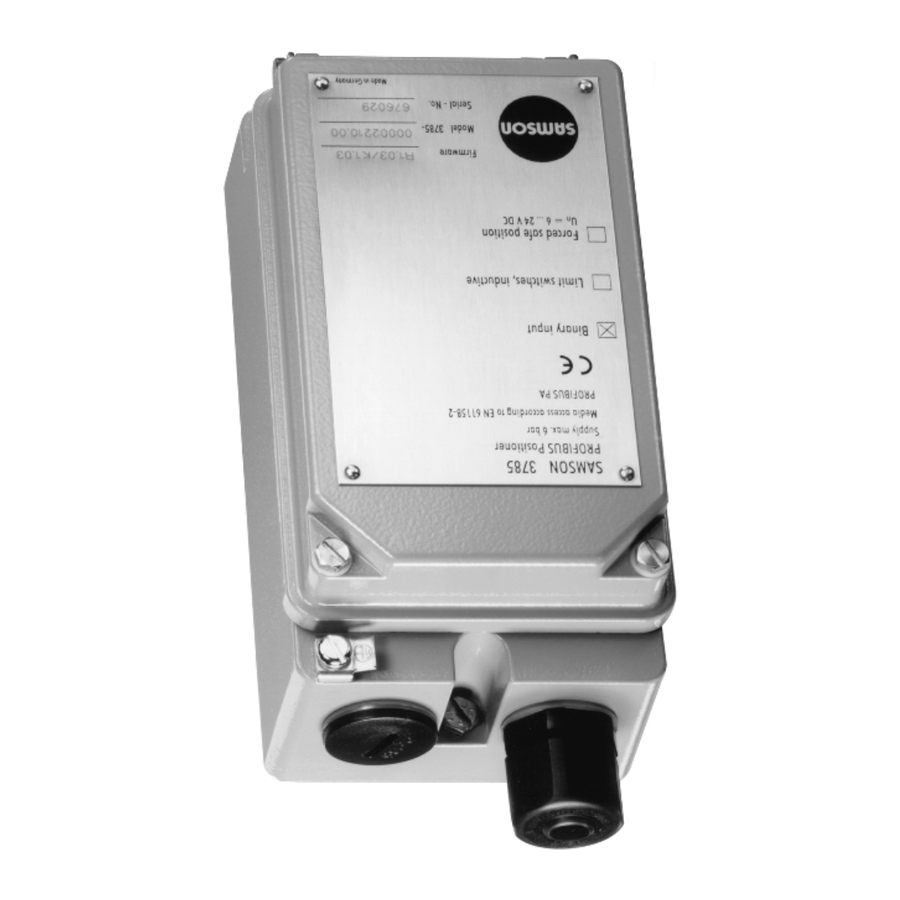
- Page 1 PROFIBUS Positioner Type 3785 PA Device Profile Version 3.0 Fig. 1 · Type 3785 Mounting and Operating Instructions EB 8382-2 EN Firmware version R 1.42/K 2.12 Edition May 2007...
-
Page 2: Table Of Contents
Contents Contents Page Design and principle of operation ....8 Options ....... . 8 Communication . - Page 3 Contents Parameter description ......42 Codes ....... . 45 7.4.1 Measured value status .
- Page 4 Safety instructions General safety instructions The positioner may only be assembled, started up or operated by trained and experienced personnel familiar with the product. According to these mounting and operating instructions, trained personnel is referred to as individuals who are able to judge the work they are assigned to and recognize possible dangers due to their specialized training, their knowledge and experience as well as their knowledge of the relevant standards.
- Page 5 Firmware modifications Modifications in the positioner firmware compared to earlier version Control R 1.23 R 1.31 Firmware adaption for new hardware version Hardware version device index .01 Control R 1.31 R 1.4 Actuator type When the actuator type is set from "linear actuator" to "rotary ac- tuator", the following applies: Initialization method .
- Page 6 Firmware modifications Initialization During initialization, the minimum control signals from 20 % to 80 % of the range of the manipulated variable are determined and saved in the EEPROM. Proportional-action The coefficients are adapted to the selected actuator type and the coefficients measured transit times.
- Page 7 POS_D is set to GOOD_MAINTENANCE_REQUIRED. X X X X X 3 X Positioner Type 3785 Not explosion protected II 2 G EEx ia IIC T6 /II 2 D IP 65 T 80 °C acc. to ATEX Ex ia FM/CSA...
-
Page 8: Design And Principle Of Operation
Design and principle of operation there is no system deviation, both the ex- Design and principle of haust and supply air valves are closed. By operation default, the positioner is equipped with a bi- nary input for floating contacts, which serves The digital PROFIBUS PA positioner is at- to signalize the switching state of an addi- tached to pneumatic control valves. - Page 9 Design and principle of operation settings are usually made on a computer. By Configuration using a segment coupler, one or more The positioner is configured and operated positioners can be connected to the PC's from the computer via the SSP interface (13) PROFIBUS segment.
-
Page 10: Technical Data
Design and principle of operation Technical data Positioner Travel, Direct attachment to Type 3277: 5 to 30 mm adjustable Attachment acc. to IEC 60534 (NAMUR): 5 to 255 mm or 30° to 120° for rotary actuators Bus connection Fieldbus interface as per IEC 61158-2 Field device acc. - Page 11 Data transmission as per PROFIBUS-PA, Profile Class B Version 3.0 acc. to DIN EN 50170 and DIN 19245 Part 4 (Version 2.0 is also available) Local interface SAMSON SSP interface for configuration and start-up Bus address Adjustable over software or microswitch, delivered state: 126...
-
Page 12: Attaching The Positioner
Direct attachment to Type 3277 Actuator The positioner can be attached either di- rectly to the SAMSON Type 3277 Actuator, Refer to Tables 1, 2 and 3 on page 15 for or according to IEC 60534-6 (NAMUR) to the required mounting parts. - Page 13 Attaching the positioner Actuator stem extends Actuator stem retracts Internal signal pressure connection Signal pressure connection over external piping Connection block Side view of connection block Venting with seal (new) with switch plate (old) Actuator stem extends Symbol Actuator stem retracts 1.2 Clamp D1 Lever...
- Page 14 Attaching the positioner associated plug included in the acces- 240, 350 and 700 cm² actuators sory kit. 6. Check whether the tongue of the seal 7. Mount the positioner so that the bore in (17) is properly aligned at the side of the distance plate (15) is aligned with the connection block with the actuator the seal located in the bore of the actua-...
- Page 15 Attaching the positioner Mounting kit Table 1 Required lever with associated clamp and distance plate Actuator size [cm Order no. D1 with stopper for Output (38) G ¼ 1400-6790 threaded connection ¼ NPT 1400-6791 D1 (33 mm in length with clamp 17 mm in height) 240 and 350 1400-6370 D2 (44 mm in length with clamp 13 mm in height)
-
Page 16: Attachment According To Iec 60534-6
Attaching the positioner Attachment according to 2.2.1 Mounting sequence IEC 60534-6 Note! Before you mount the parts, apply a signal Refer to Tables 4 and 5 on page 19 for re- pressure to the actuator so that the valve is quired accessories. - Page 17 Attaching the positioner Mounting position Attachment to NAMUR rib Lever N1, N2 Attachment to rods Plate Clamp Clamping plate Screw Pointer Shaft Lever of positioner 27a Transmission pin 27b Counter nut Bracket Studs Plate Nuts Mounting bracket Fig. 4 · Attachment according to IEC 60534-6 (NAMUR) EB 8382-2 EN...
-
Page 18: Presetting The Valve Travel
Attaching the positioner Intermediate values must be calculated. 5. Measure the distance between the center of the shaft (25) and the center of the pin (19). You will be prompted for this value later during the configuration of the positioner. 2.2.2 Presetting the valve travel 1. - Page 19 Attaching the positioner Table 4 NAMUR Valve Travel [mm] With lever Order no. attachment 7.5 to 60 N1 (125 mm) 1400-6787 Valve with cast yoke 30 to 120 N2 (212 mm) 1400-6789 20 to 25 1400-6436 NAMUR mounting kit, 20 to 25 1400-6437 Valve with 25 to 30...
-
Page 20: Attachment To Rotary Actuators
(see section 2.3.4). Actuators by other manufacturers: If the positioner is attached to SAMSON 1. Position complete intermediate piece Type 3278 Rotary Actuator, the air ex- (34, 42, 44 and 45) on the bracket (fix-... - Page 21 Attaching the positioner Attachment to SAMSON Type 3278 Attachment acc. to VDI/VDE 3845 Vent plug or filter check valve 33 Positioner 40 Cam disk 34 Intermediate piece 41 Actuator shaft 35 Lever with cam follower 42 Plate roll 43 Bracket...
-
Page 22: Aligning And Mounting The Cam Disk
Attaching the positioner 2.3.3 Aligning and mounting the In actuators with fail-safe position "Valve cam disk open" (OPEN), the actuator must therefore be loaded with the max. signal pressure In rotary actuators with spring-return mech- prior to aligning the cam disk. In springless anism, the built-in actuator springs deter- actuators, the supply air must be connected. - Page 23 Control valve opens clockwise Fig. 6 · Aligning the cam disk Rotary actuators Complete mounting parts, but without cam disk Table 6 Attachment acc. to SAMSON Type 3278 [cm Attachment to Masoneilan actuator VDI/VDE 3845, level 1 Camflex I Camflex I Camflex II DN 25...100...
-
Page 24: Reversing Amplifier For Double-Acting Actuators
Attaching the positioner 5. Replace venting plug on the reversing 2.3.4 Reversing amplifier for amplifier with the enclosed filter check double-acting actuators valve. For use with double-acting actuators, the positioner must be fitted with a reversing Signal pressure connections amplifier. The reversing amplifier is listed as A1: Output A1 leading to the signal pres- an accessory in Table 6 on page 23. - Page 25 Attaching the positioner From the positioner Control signals to the actuator Reversing amplifier 1.1 Special screws 1.2 Flat gasket 1.3 Special nuts 1.4 Rubber seal 1.5 Plug 1.6 Filter Fig. 7 · Attaching a reversing amplifier EB 8382-2 EN...
-
Page 26: Connections
Connections Connections 3.1.1 Pressure gauge To monitor the operation of the positioner, it Pneumatic connections is recommended to connect pressure gauges for supply air and signal pressure indication The air connections are either ¼ NPT or to the positioner. These parts are listed as G ¼... -
Page 27: Supply Air Pressure
Connections 3.1.2 Supply air pressure Electrical connections The required supply pressure depends on For electrical installation, you are re- the bench range and the operating direction quired to observe the relevant regu- (fail-safe action) of the actuator. The bench lations and accident prevention reg- range is indicated on the nameplate as ulations that apply in the country of spring range or signal pressure range. - Page 28 Connections Bus line Caution! The shielded PROFIBUS connecting cable The terminal assignment specified in the cer- must be routed over the EMC-proof brass tificate must be adhered to. Reversing the cable gland (standard) of the positioner to assignment of the electrical terminals may the terminals.
-
Page 29: Forced Venting
Connections At the binary input, a passive floating con- 3.2.1 Forced venting tact can be used. The positioner signals the circuit status via the bus protocol. For positioners with forced venting function, a voltage of 6 to 24 V DC must be applied to the relevant terminals. -
Page 30: Limit Switches
0 and 125. Seven micro switches lo- The TROVIS-VIEW software and the data- cated on the inside of the positioner's base module 3785 are required in version hinged cover serve to enter the bus address 2.02.The positioner can also be accessed as binary information. - Page 31 Master Class 1) elements Termination Master Class 2) Segment coupler Termination ↑ 10.1 Connection of Type 3785 Positioners ↓ 10.2 Connection of Type 3785-1 Positioners in hazardous area Controller/PLC/Control system Display and control Master Class 1) elements Termination Master Class 2)
-
Page 32: Operation
Operation Operation LED controls Two LEDs located inside the cover help mon- Warning! itor the positioner, indicating the positioner's Before putting the positioner into op- status during maintenance procedures, op- eration, carefully move the valve to eration and in the event of defects. its final position by covering the hole The colors generally indicate the following: (manual operation) on the cover... -
Page 33: Write Protection
Operation 3. Set switch to desired position: Write protection 1 ENABLED > Function activated A microswitch marked "write protection" is 2 DISABLED > Function deactivated located to the right of the seven bus address selector switches inside the hinged cover. Default settings When activated (position ON), the positioner settings are write protected, so... -
Page 34: Adjusting Mechanical Zero
Operation 4.4.1 Adjusting mechanical zero Caution! The initialization routine takes sev- eral minutes. During that time, the Note! Zero must be adjusted with the valve closed valve changes its position. Therefore, (for three-way valves with the actuator stem never initialize the positioner during extended). - Page 35 Operation Final position at a reference variable less "Reset to default values". After this, the than –2.5% (function deactivated), final Init/Zero key can be pressed to start a com- position at a reference variable larger plete initialization. than 99 % (tight closing). Electric zero calibration Set delay time to at least 30 seconds.
-
Page 36: Adjusting The Inductive Limit Switches
Operation Adjusting the inductive limit Adjusting the switching point: switches The limit switches are marked GW1 and GW2 on the inside of the case cover. Yellow The positioner version with inductive limit tags and the associated adjustment screws switches has two adjustable tags which are (Fig. -
Page 37: Maintenance
Maintenance Maintenance Servicing explosion-protected devices The positioner is maintenance free. The pneumatic connection 9/Supply contains a If a part of the positioner on which the ex- filter with a mesh size of 100 μm. If neces- plosion protection is based needs to be ser- sary, the filter can be unscrewed and viced, the positioner must not be put back cleaned. -
Page 38: How To Implement The Profibus Master Class 1
1400-7417 on a 1.44 MB disc (3½"). Alternatively, they can be downloaded from the fol- lowing sites: http://www.samson.de or http://www.profibus.com. The device database files enable the standardized implementation of the SAMSON Type 3785 Positioner in the programming and configuration environment of a Master Class 1 as PROFIBUS slave unit (example: SIEMENS Simatic Step 7, HWConfig). - Page 39 How to implement the PROFIBUS Master Class 1 Variant 2: Module = “RCAS_OUT, RCAS_IN“ 0xB4 or 0xC2, 0x84, 0x84, 0x82, 0x8C Input value (Input) Byte 0 Octet 1 Octet 2 Octet 3 Octet 4 Octet 5 Sign, Exponent, Exponent Fraction Fraction Fraction RCAS_OUT, Value...
- Page 40 How to implement the PROFIBUS Master Class 1 Variant 4: Module = “CHECKBACK, SP“ 0x92, 0xA4, or 0xC2, 0x84, 0x82, 0x82, 0x92 Input value (Input) Byte 0 Octet 1 Octet 2 Octet 3 CHECK_ CHECK_ CHECK_ BACK[0] BACK[1] BACK[2] Output value (Output) Byte 0 Octet 1 Octet 2...
- Page 41 How to implement the PROFIBUS Master Class 1 Variant 6: Module = “RCAS_OUT + CHECKBACK, RCAS_IN“ 0x97, 0xA4, or 0xC2, 0x84, 0x87, 0x82, 0x9C Input value (Input) Byte 0 Octet 1 Octet 2 Octet 3 Octet 4 Octet 5 Octet 1 Octet 2 Octet 3 Sign,...
-
Page 42: Parameter Description
How to implement the PROFIBUS Master Class 1 Output value (Output) Byte 0 Octet 1 Octet 2 Octet 3 Octet 4 Octet 5 Octet 1 Octet 2 Octet 3 Octet 4 Octet 5 Sign, Exponent, Sign, Exponent, Exponent Fraction Fraction Fraction Exponent Fraction... - Page 43 How to implement the PROFIBUS Master Class 1 The message value is encoded as follows: 0 = not initialized 1 = closed (x < 0.5 %) 2 = open (x > 99.5 %) 3 = intermediate position CHECKBACK – Device status: Detailed device information, bit-wise encoded Each bit can be hidden by the Class 2 master for cyclic communication.
- Page 44 How to implement the PROFIBUS Master Class 1 Device diagnosis messages "Slave Diagnostic Information" Each bit can be hidden by the Class 2 master for cyclic communication. This allows a specific selection to be made from the existing messages. In addition to the standard diagnosis messages, the positioner can provide other messages as "Ext_Diag_Data".
-
Page 45: Codes
How to implement the PROFIBUS Master Class 1 Codes 7.4.1 Measured value status The following status codes are used by the Type 3785 Positioner: Valid value Bad: Substatus Condition Value (decimal) configuration Error Error in device configuration, value cannot be... -
Page 46: Set Point Status
How to implement the PROFIBUS Master Class 1 Good (Non-Cascade) Valid value Substatus Condition Value Everything is ok, no further status available maintenance required Transit time monitoring active or zero point error active or total valve travel exceeded 7.4.2 Set point status Good (Non-Cascade) Substatus Condition... -
Page 47: Operating Modes
How to implement the PROFIBUS Master Class 1 Operating modes Operating modes of the AO (Analog Output) Out of Service (OS) Local Override (LO) Manual (Man) Automatic (Auto) Remote Cascade (RCAS) Out of Service (OS) The AO algorithm of the component is not executed. The control valve is moved to fail-safe posi- tion. -
Page 48: Start-Up (Warm Start)
How to implement the PROFIBUS Master Class 1 Operating modes of the Transducer Block Out of Service (OS) In this operating mode, the correction value received from the AO Function Block is not used. The control valve is moved to the fail-safe position determined via ACT_FAIL_ACTION. The positioner also switches to operating mode OS when the forced venting function has been acti- vated. - Page 49 How to implement the PROFIBUS Master Class 1 Mode Auto If the status of the reference variable (SP) is bad, the action determined via FSAFE_TYPE is exe- cuted after the fail-safe time (FSAFE_TIME) has elapsed. Mode RCAS In RCAS mode, the positioner switches to automatic mode after the fail-safe time (FSAFE_TIME) has elapsed, unless the status of the reference variable RCAS_IN is "good-cascade".
- Page 50 EB 8382-2 EN...
-
Page 51: List Of Parameters
The list of parameters following the overview is in alphabetical order and describes all parame- ters of the positioner which can be displayed or modified via PROFIBUS communication, e.g. on a PC. Manufacturer-specific parameters of the SAMSON Type 3785 PROFIBUS PA Positioner are marked with (M). Summary of parameters Device identification Loop/tag identification . - Page 52 List of parameters Additional component serial number ..ADD_GEAR_SER_NUM Additional component manufacturer ..ADD_GEAR_MAN Additional component identification ..ADD_GEAR_ID Additional component installation date .
- Page 53 List of parameters Device settings Configuration Write protection ....HW_WRITE_PROTECTION Reference variable range ....PV_SCALE Fail-safe value reference variable .
- Page 54 List of parameters Valve position feedback, discrete ..POS_D Set point deviation e ....SETP_DEVIATION Correction value .
-
Page 55: Parameters
List of parameters Parameters Clearly identifies the manufacturer of the actuator. Actuator manufacturer ACTUATOR_MAN Length: 16 characters Identifies the actuator design. Actuator type ACTUATOR_TYPE Read-only parameter, determined by the actuator. States: 0 = Electropneumatic 1 = Electric 2 = Electrohydraulic 3 = Other Default: Actuator version with/without spring return mechanism. - Page 56 VDI/VDE 3845 (NAMUR) is possible. ATTACHMENT (M) For more details on attachments, also see sections 2.1 and 2.2. 0 = Integral > attachment in combination with a SAMSON Type 3277 Actuator States: 1 = NAMUR > attachment according to IEC 60534-6 (NAMUR)
- Page 57 2 = Equal percentage reverse 3 = User-defined (supported in a future firmware version) 4 = SAMSON butterfly control valve, linear 5 = SAMSON butterfly control valve, equal percentage 6 = VETEC rotary plug valve, linear 7 = VETEC rotary plug valve, equal percentage Default: Text field (32 characters) to enter a description of the adjusted characteristic.
- Page 58 List of parameters Indicates current valve position in unit OUT_SCALE Controlled variable of Transducer Block FEEDBACK_VALUE Indicates the date of the last calibration of the field device. Date last calibration DEVICE_CALIB_DATE Indicates the date of the last configuration of the field device. Date last configuration DEVICE_CONFIG_DATE Indicates the date on which the field device was installed.
- Page 59 List of parameters Detailed device information, bit-wise encoded which enables several simultaneous Diagnosis messages, also see section 9. DIAGNOSIS Message type: A: Dynamic messages; they are automatically reset when they are read. R: Static messages; they are retained as long as the event is present in the field States: device.
- Page 60 List of parameters If the reference variable exceeds the entered limit, the valve moves towards the end Final position when reference position corresponding to 100 % of the reference variable. variable is above the limit value Hysteresis 1%. SETP_CUTOFF_INC When the value is 125 %, the function is deactivated. Default: 99 % Caution! Since the actuator will automatically be filled with air or vented when this...
- Page 61 List of parameters Method of initialization related to the nominal or maximum range. Initialization method INIT_METHOD (M) For initialization in the nominal range, only the range of the manipulated variable entered under rated travel/nominal angle is considered (e.g. globe valve with me- chanical stop on one side).
- Page 62 List of parameters Positioner operating mode Operating mode, target Firmware Version K 1.20 and lower: OS, AUTO Operating mode, current Firmware Version K 1.30 and higher: OS, LO, MAN, AUTO MODE_BLK/ Positioner operating modes: TARGET_MODE Automatic (AUTO): In this operating mode, the positioner follows the cyclic or acyclic set point entered via the parameter SP (w) according to the scale and unit entered via PV_SCALE (ref- erence variable range).
- Page 63 List of parameters The action determined by the parameter FSAFE_TYPE (fail-safe action) is triggered by the following events: • Start-up (warm start) of the positioner • Elapsing of the DP watchdog through interruption of the cyclic communication with a Master Class 1 (not applicable when communication is terminated properly).
- Page 64 List of parameters Proportional-action coefficient for exhaust air. Proportional-action coefficient KP_Y2 When writing, the value is written to KP_Y2 (exhaust air). KP_Y1 (supply air) remains SERVO_GAIN_2 unchanged. We recommend to adjust the value in increments of 0.1 when adjusting the value in the range from 0.01 to 10.0.
- Page 65 List of parameters Set point with status Reference variable w Reference variable w in "AUTO" operating mode Also see reference variable range. Set point with status Reference variable w_rcas RCAS_IN/RCAS_OUT Reference variable w in "RCAS" operating mode Also see reference variable range. Storage place for a password to be used by the host, serves to check access rights Security locking (format: 16-bit unsigned integer).
- Page 66 List of parameters Total valve travel, sum of nominal duty cycles (double up-and-down travels) Total valve travel TOTAL_VALVE_TRAVEL Maximum value: 16 500000 Total valve travel limit value. Total valve travel limit value TOTAL_VALVE_TRAVEL_LIM Range 0 to 16 500 000 Default: 1 000 000 The minimum transit time OPEN (towards the 100 % position) is the actual time in Transit time - minimum OPEN...
- Page 67 List of parameters Only for linear actuator with positioner attached according to NAMUR. Transmission pin position TRANSM_PIN_POS (M) Pin position on the positioner lever, see marking on the positioner lever. States: 0 = A 1 = B Default: Lower limitation of valve travel/angle of rotation to the entered value. Travel/angle limit Range –20.0 to 99.9 %.
- Page 68 List of parameters Describes the valve type. Valve type VALVE_TYPE States: 0 = Control valve with linear motion of the control element 1 = Control valve with rotary motion of the control element, part turn, rotary motion Default: Command to reset the device (warm start). Warm start DEVICE_RESET_CMD States:...
-
Page 69: Messages And Diagnosis
Messages and diagnosis Messages and diagnosis The Type 3785 PROFIBUS PA Positioner provides the best possibilities for diagnosis during the initialization process. In automatic mode, detailed tests are carried out to check and evaluate the attachment situation and the positioner's reaction, taking into account the preset or entered data. - Page 70 Messages and diagnosis DIA_CONF_INVAL Incorrect configuration – invalid bus address Set when the address switch is adjusted to the invalid address 127. Device starts with default address 126. DIA_WARMSTART Reset (warm start) completed Displayed when the device was reset via warm start. This reset is triggered following an electric power failure or by "DEVICE_RESET_CMD = 1".
-
Page 71: Check_Back Messages
Messages and diagnosis CHECK_BACK messages Bit no. Name Description R = Static message, remains valid while the error is present in the field device A = Dynamic message, automatically reset when read CB_FAIL_SAVE Fail-safe position The fail-safe position was activated by the device, either by se- lecting operating mode "OUT OF SERVICE", by activating the forced venting function, or by a communication failure. - Page 72 Messages and diagnosis CB_CONTR_ERR Internal control loop error Displayed when the positioner is unable to control the adjusted range of tolerance for error messages within the preset delay time. Possible sources of error: > Oscillation caused by actuator operated too rapidly (small travel volume) >...
-
Page 73: Initialization Messages
Messages and diagnosis Initialization messages Description Not defined The device has not been initialized or a cold start was performed. Automatically reset after confirmation. Aborted The initialization routine was canceled by the user. Automatically reset after confirmation. If the device has already been successfully initialized and no cold start was performed, the device returns to control operation. - Page 74 Messages and diagnosis Air leakage in pneumatic system The actuator must stall for a few seconds when the duty cycle is being determined initially. This time is used to check the pneumatic system for leaks. If the control valve moves more than 9.3 % from its resting position in 7 seconds, the relevant message is issued and additionally, an initialization warning is indicated.
-
Page 75: Dimensional Drawing
Dimensional drawing Pneumatic connection G ¼ or ¼ NPT Direct attachment Fulcrum of Attachment with distance actuator shaft piece for rotary actuators Attachment acc. to IEC 60534 w. adapter housing Pneumatic connection Reversing amplifier EB 8382-2 EN... -
Page 76: Test Certificates
EB 8382-2 EN... - Page 77 EB 8382-2 EN...
- Page 78 EB 8382-2 EN...
- Page 79 EB 8382-2 EN...
- Page 80 Messages and diagnosis EB 8382-2 EN...
- Page 81 EB 8382-2 EN...
- Page 82 SAMSON AG · MESS- UND REGELTECHNIK Weismüllerstraße 3 · 60314 Frankfurt am Main · Germany Phone: +49 69 4009-0 · Fax: +49 69 4009-1507 EB 8382-2 EN Internet: http://www.samson.de...
Need help?
Do you have a question about the 3785 and is the answer not in the manual?
Questions and answers