Advertisement
Quick Links
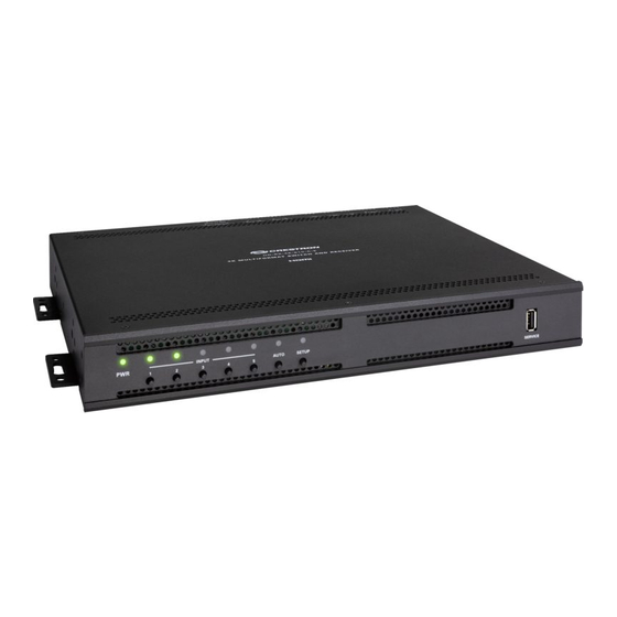
HD-RX-4K-510-C-E
DM Lite™ 4K Multiformat Switch and Receiver
The Crestron® HD-RX-4K-510-C-E is a DM Lite™ 4K multiformat switch and receiver that
provides enhanced HDMI® video switching and audio presentation capabilities in areas such as
conference rooms and classrooms. The HD-RX-4K-510-C-E can be connected to up to three
DM Lite transmitters.
Check the Box
Item
HD-RX-4K-510-C-E
Anchor, Drywall, Plastic (P/N 2053825)
Connector, 2-Pin (P/N 2003574)
Connector, 2-Pin (P/N 2044402)
Connector, 3-Pin (P/N 2003575)
Connector, 5-Pin (P/N 2003577)
Power Cord, 6 ft 7 in. (2 m) (P/N 2001134)
Screw, 8-15A x 3/4 in., Flat Head, Phillips (P/N 2053836)
Install the Device
To install the device, mount it onto drywall. Use the four included drywall anchors and the four
included 8-15A x 3/4 in. flat head Phillips screws (one screw for each keyhole slot in the four
mounting flanges of the device).
NOTE:
For safety reasons, it is recommended that the mounting height of the device be no more
than 6-1/2 ft (2 m) from the floor or any platform above which the device is mounted.
Drywall Mounting
Drywall
HD-RX-4K-510-C-E
(4) Mounting flange
(4) Screws, 8-15A x 3/4 in.
keyhole slots
(included)
(2 each side)
Connect the Device
Connect the device as required for the application.
Front Panel Connection
INPUT Selection
LEDs and
PWR
LED
push buttons
Qty
1
4
5
2
Rear Panel Connections
3
5
From balanced
1
microphone
audio sources
4
LINE L/R 1-2 :
From balanced/
unbalanced stereo line
level audio sources
DM LITE
INPUTS 5, 4, 3:
From
DM Lite™
transmitters
NOTES:
•
Cabling that connects the HD-RX-4K-510-C-E to a DM Lite transmitter is designed for
intrabuilding use only.
•
The HD-RX-4K-510-C-E can power three DM Lite transmitters simultaneously. Do not
connect power to transmitters that are to be connected to the HD-RX-4K-510-C-E.
(4) Anchors
(included)
•
The HD-RX-4K-510-C-E is grounded by connection of the included power cord to an
AC power outlet with proper grounding.
•
There are no user-serviceable parts inside this device. If repair of the device is needed,
contact an authorized Crestron dealer for return of the device to the factory.
SERVICE:
1-5
AUTO
SETUP
For firmware
LED and
LED and
and EDID
push button
push button
loading
MIC 1-2:
AUX OUT 1-2:
To balanced/
SPEAKER L/R OUT:
100-240V~2.0A
AUX:
From balanced
unbalanced
To 4-ohm or
auxiliary
auxiliary
8-ohm
audio devices
stereo speakers
audio source
HDMI
HDMI
I/O 1-2:
RLY 1-2:
INPUTS 2, 1:
OUTPUT:
To I/O
To contact
From HDMI®
To HDMI
controllable
closure
audio/video
display
devices
devices
sources
:
IR:
100BASE-TX/
To IR
1000BASE-T
controllable
Ethernet to
device
local area network
LINE 1-2 Connector Pin Assignments
The LINE 1 and LINE 2 connectors use 5-pin terminal blocks for balanced or unbalanced analog
audio inputs.
LINE 1-2 Connector
+
–
+ –
Refer to the following table and diagrams for analog audio input pin assignments and
connection information.
Signal Name
Balanced Audio Input
+
L+
–
L–
G
Shield/ground
+
R+
–
R–
50/60 Hz:
Balanced Input
Unbalanced Input
From AC
power outlet
L
R
+ - G + -
Shield
+
Source L
Source L
+
Source R
Source R
COM:
To RS-232
device
AUX OUT 1-2 Connector Pin Assignments
The AUX OUT 1 and AUX OUT 2 connectors use 5-pin terminal blocks for balanced or unbalanced
analog audio outputs.
AUX OUT 1-2 Connector
+
–
+ –
Refer to the following table and diagrams for analog audio output pin assignments and
connection information.
Signal Name
Balanced Audio Output
+
L+
–
L–
G
Shield/ground
+
R+
–
R–
Balanced Output
Unbalanced Output
L
R
L
+ - G + -
+ - G + -
Shield
Right
+
AMP
Left
+
Unbalanced Audio Input
L+ In
L– signal return, jumper to GND
Ground
R+ In
R– signal return, jumper to GND
L
R
+ - G + -
+
Jumpers
Shield
+
Shield
Unbalanced Audio Output
L+ Out
Open
Common ground
R+ Out
Open
R
+
Right
AMP
Left
+
Advertisement

Summary of Contents for Crestron DM Lite HD-RX-4K-510-C-E
- Page 1 DM Lite™ 4K Multiformat Switch and Receiver LINE 1-2 Connector Pin Assignments The Crestron® HD-RX-4K-510-C-E is a DM Lite™ 4K multiformat switch and receiver that Connect the Device provides enhanced HDMI® video switching and audio presentation capabilities in areas such as The LINE 1 and LINE 2 connectors use 5-pin terminal blocks for balanced or unbalanced analog conference rooms and classrooms.
- Page 2 CAN ICES-3 (B)/NMB-3(B) Crestron, the Crestron logo, and DM Lite are either trademarks or registered trademarks of Crestron Electronics, Inc. in the This device complies with part 15 of the FCC Rules. Operation is subject to the following conditions: (1) This device may not United States and/or other countries.


Need help?
Do you have a question about the DM Lite HD-RX-4K-510-C-E and is the answer not in the manual?
Questions and answers