Advertisement
Quick Links
Fingerprint Access Control Terminal
Quick Start Guide
UD17820B
©2019 Hangzhou Hikvision Digital Technology Co., Ltd.
It includes instructions on how to use the Product. The software
embodied in the Product is governed by the user license agreement
covering that Product.
About this Manual
This Manual is subject to domestic and international copyright
protection. Hangzhou Hikvision Digital Technology Co., Ltd.
("Hikvision") reserves all rights to this manual. This manual cannot
be reproduced, changed, translated, or distributed, partially or
wholly, by any means, without the prior written permission of
Hikvision.
Trademarks
and other Hikvision marks are the property of Hikvision
and are registered trademarks or the subject of applications for the
same by Hikvision and/or its affiliates. Other trademarks mentioned
in this manual are the properties of their respective owners. No right
of license is given to use such trademarks without express
permission.
Legal Disclaimer
TO THE MAXIMUM EXTENT PERMITTED BY APPLICABLE LAW, THE
PRODUCT DESCRIBED, WITH ITS HARDWARE, SOFTWARE AND
FIRMWARE, IS PROVIDED "AS IS", WITH ALL FAULTS AND ERRORS,
AND HIKVISION MAKES NO WARRANTIES, EXPRESS OR IMPLIED,
INCLUDING WITHOUT LIMITATION, MERCHANTABILITY, SATISFACTO-
RY QUALITY, FITNESS FOR A PARTICULAR PURPOSE, AND NON-IN-
FRINGEMENT OF THIRD PARTY. IN NO EVENT WILL HIKVISION, ITS
DIRECTORS, OFFICERS, EMPLOYEES, OR AGENTS BE LIABLE TO YOU
FOR ANY SPECIAL, CONSEQUENTIAL, INCIDENTAL, OR INDIRECT
DAMAGES, INCLUDING, AMONG OTHERS, DAMAGES FOR LOSS OF
BUSINESS PROFITS, BUSINESS INTERRUPTION, OR LOSS OF DATA OR
DOCUMENTATION, IN CONNECTION WITH THE USE OF THIS
PRODUCT, EVEN IF HIKVISION HAS BEEN ADVISED OF THE POSSIBILI-
TY OF SUCH DAMAGES.
REGARDING TO THE PRODUCT WITH INTERNET ACCESS, THE USE OF
PRODUCT SHALL BE WHOLLY AT YOUR OWN RISKS. HIKVISION SHALL
NOT TAKE ANY RESPONSIBILITIES FOR ABNORMAL OPERATION,
PRIVACY LEAKAGE OR OTHER DAMAGES RESULTING FROM CYBER
ATTACK, HACKER ATTACK, VIRUS INSPECTION, OR OTHER INTERNET
SECURITY RISKS; HOWEVER, HIKVISION WILL PROVIDE TIMELY
TECHNICAL SUPPORT IF REQUIRED.
SURVEILLANCE LAWS VARY BY JURISDICTION. PLEASE CHECK ALL
RELEVANT LAWS IN YOUR JURISDICTION BEFORE USING THIS
PRODUCT IN ORDER TO ENSURE THAT YOUR USE CONFORMS THE
APPLICABLE LAW. HIKVISION SHALL NOT BE LIABLE IN THE EVENT
THAT THIS PRODUCT IS USED WITH ILLEGITIMATE PURPOSES.
IN THE EVENT OF ANY CONFLICTS BETWEEN THIS MANUAL AND THE
APPLICABLE LAW, THE LATER PREVAILS.
1
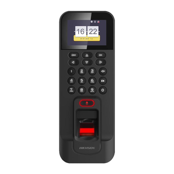
Appearance
2.4-inch LCD Display
Screen Indicator
Keypad
Door Bell
Button
Fingerprint
Reading Module
2
Installation
1. Install 120 or 86gang box into the wall.
3
Activation
Activating via Device
Power on and wire the network cable after installation.
You should activate the device before the first login.
After powering on, the interface will be displayed as
follows.
You can create the device password and confirm the
password to activate.
The default values of the terminal are as follows:
• The default IP address: 192.0.0.64
• The default port No.: 8000
• The default user name: admin
RS-485/Wiegand Wiring Terminal
Exiting Key
Direction Keys
Tamper-proof
Button
Ethernet Port
Door Lock
Wiring Terminal
12V
Alarm
Numeric Keys/
Power Interface
Wiring Terminal
Letter Keys
USB Interface/
Reset Button
Note:
Long press Key 6 for 3s to enter One-Touch Wi-Fi Settings mode. You can set Wi-Fi parameters
(Inside of the Cover)
for the device via the App on the phone. Press Key 6 again to exit the mode. (The model with "-1"
does not support One-Touch Wi-Fi Settings mode.)
2. Route the cables through the cable hole of
the mounting plate.
3. Secure the device mounting plate on the gang
box with two screws. (Supplied).
Activating via SADP
1. Download SADP Software: Get the SADP software from the supplied disk or the official website. Install and run the software.
2. Activate Device: Check the inactive device from the device list. Create a password in the right side of the interface and confirm the password.
3. Edit Device IP Address: Check the device and manually edit the device IP address, Port No., Subnet Mask, Gateway, etc.
Activating via Client Software
1. Get the client software from the supplied disk or the official website. Install and run the client software.
2. Click Device Management to enter the Device Management interface.
3. Select an inactive device from the Online Device list. Click Activate to pop up the Activation interface.
4. Create a password and confirm the new password. Click OK to activate the device.
4. Click "Modify Netinfo" to set the device IP address, mask address, gateway address, and port No.
Online Devices (2)
Add to Client
Add All
Modify Netinfo
IP
Device Type
Firmware Version
xx.xx.xx.xx
xxxxxxxxxxxxx
xxxxxxxxxxxxx
xx.xx.xx.xx
xxxxxxxxxxxxx
xxxxxxxxxxxxx
Keypad Descriptions
OK Key
ESC
OK
OK Key: Press to confirm operations. Press and hold the
key for 3s to login the main interface.
Deleting Key:
2
3
Deleting
1
1.Press to delete the letters or numbers one by one;
ABC
DEF
Key
2.Long-press to clear all contents in the textbox;
4
5
6
EN
GHI
JKL
MNO
7
8
9
0
PQRS
TUV
WXYZ
Editing Key
Editing Key: Press to enter the editing status. Shift among
numbers/lowercases, numbers/uppercases and symbols.
4. Connect the corresponding cables.
5. Align the terminal with mounting plate. Push the
terminal in the mounting plate from bottom up.
Fasten the terminal with the buckles on the plate.
STRONG PASSWORD RECOMMENDED
We highly recommend you create a strong password of your own choosing
(using a minimum of 8 characters, including upper case letters, lower case
letters, numbers, and special characters) in order to increase the security of
your product. And we recommend you reset your password regularly,
especially in the high security system, resetting the password monthly or
weekly can better protect your product.
Refresh Every 60s
Activate
Reset Password
Filter
Security
Server Port
Device Serial No.
Inactivate
8000
XX-XXXXXX
Activate
8000
XX-XXXXXX
Mounting Screw
Anticlockwise Rotation
6. Tighten the screws to fix the terminal on the
mounting plate and complete the installation.
Advertisement

Related Manuals for HIKVISION K1T804AEF


Summary of Contents for HIKVISION K1T804AEF
- Page 1 About this Manual This Manual is subject to domestic and international copyright protection. Hangzhou Hikvision Digital Technology Co., Ltd. (“Hikvision”) reserves all rights to this manual. This manual cannot be reproduced, changed, translated, or distributed, partially or Activation wholly, by any means, without the prior written permission of Activating via SADP Hikvision.
- Page 2 Note: The external power supply and the secure door control terminal should use the same GND cable. You can view the device License via the website: http://opensource.hikvision.com/Home/List?id=46 Regulatory Information This product and - if applicable - the supplied accessories too are marked with "CE"...
Need help?
Do you have a question about the K1T804AEF and is the answer not in the manual?
Questions and answers