Table of Contents
Advertisement
Quick Links
Advertisement
Table of Contents

Related Manuals for HIKVISION DS-K1T804A Series


Summary of Contents for HIKVISION DS-K1T804A Series
- Page 1 DS-K1T804A Series Fingerprint Access Control Terminal User Manual UD18256B-A...
- Page 2 MERCHANTABILITY, SATISFACTORY QUALITY, OR FITNESS FOR A PARTICULAR PURPOSE. THE USE OF THE PRODUCT BY YOU IS AT YOUR OWN RISK. IN NO EVENT WILL HIKVISION BE LIABLE TO YOU FOR ANY SPECIAL, CONSEQUENTIAL, INCIDENTAL, OR INDIRECT DAMAGES, INCLUDING, AMONG OTHERS, DAMAGES FOR LOSS OF...
- Page 3 THE APPLICABLE LAW, THE LATER PREVAILS. Data Protection During the use of device, personal data will be collected, stored and processed. To protect data, the development of Hikvision devices incorporates privacy by design principles. For example, for device with facial recognition features, biometrics data is stored in your device with encryption method;...
- Page 4 Symbol Conventions The symbols that may be found in this document are defined as follows. Symbol Description Indicates a hazardous situation which, if not avoided, Danger will or could result in death or serious injury. Indicates a potentially hazardous situation which, if not avoided, could result in equipment damage, data Caution loss, performance degradation, or unexpected...
- Page 5 Regulatory Information FCC Information Please take attention that changes or modification not expressly approved by the party responsible for compliance could void the user’s authority to operate the equipment. FCC compliance: This equipment has been tested and found to comply with the limits for a Class B digital device, pursuant to part 15 of the FCC Rules.
- Page 6 the EMC Directive 2014/30/EU, the RoHS Directive 2011/65/EU 2012/19/EU (WEEE directive): Products marked with this symbol cannot be disposed of as unsorted municipal waste in the European Union. For proper recycling, return this product to your local supplier upon the purchase of equivalent new equipment, or dispose of it at designated collection points.
- Page 7 Cet équipement doit être installé et utilisé à une distance minimale de 20 cm entre le radiateur et votre corps.
- Page 8 Safety Instruction These instructions are intended to ensure that user can use the product correctly to avoid danger or property loss. The precaution measure is divided into Dangers and Cautions: Dangers: Neglecting any of the warnings may cause serious injury or death.
- Page 9 • Improper use or replacement of the battery may result in hazard of explosion. Replace with the same or equivalent type only. Dispose of used batteries according to the instructions provided by the battery manufacturer. • You can view the device License via the website: http:// opensource.hikvision.com/Home/List?id=46. viii...
- Page 10 Available Models The fingerprint access control terminal contains the following models: Product Name Model Description Supports fingerprint DS-K1T804AF only. Fingerprint Access Supports presenting DS-K1T804AMF Control Terminal Mifare card. Supports presenting DS-K1T804AEF EM card. Use only power supplies listed in the user instructions: Model Manufacturer Standard...
-
Page 11: Table Of Contents
Contents 1 Overview ..............1 2 Features ..............1 3 Appearance Description ..........2 4 Device Wiring ............4 4.1 Terminal Description ..........4 4.2 External Device Wiring .......... 6 4.3 Secure Door Control Unit Wiring ......7 5 Installation ............... 7 6 Activation .............. - Page 12 7.6.2 Set Access Control Parameters ....20 7.6.3 Set Holiday Group ........21 7.6.4 Set Week Plan ..........22 7.6.5 Set Schedule Template ......23 7.7 Attendance Status ..........24 7.7.1 Set Auto Attendance ........24 7.7.2 Set Manual Attendance ......25 7.7.3 Set Manual and Auto Attendance .....
- Page 13 8.1.2 Add Device by IP Address or Domain Name ................41 8.1.3 Add Devices by IP Segment ....... 42 8.1.4 Add Device by EHome Account ....43 8.1.5 Import Devices in a Batch ......45 8.2 Person Management ........... 46 8.2.1 Add Organization ........
- Page 14 8.5.1 Configure Device Parameters ....59 8.5.2 Configure Remaining Open/Closed ... 63 8.5.3 Configure Custom Wiegand Rule ....64 8.5.4 Configure Card Reader Authentication Mode and Schedule ............65 8.5.5 Configure Other Parameters ...... 66 8.6 Configure Linkage Actions for Access Control ..69 8.6.1 Configure Client Actions for Access Event ................
- Page 15 9.1 View Device Information ........96 9.2 Change Device Password ........96 9.3 Time Management ..........97 9.4 System Maintenance .......... 97 9.5 Configure RS-485 Parameters ......98 9.6 Security Mode Settings ........98 9.7 Network Parameters Settings ......99 9.8 Report Strategy Settings ........
-
Page 16: Overview
1 Overview DS-K1T804A series fingerprint access control terminal is designed with a 2.4-inch LCD display screen. Offline operation, wired network (TCP/IP) and wireless network transmission modes are supported as well. (The models with -1 do not support the wireless network function.) 2 Features •... -
Page 17: Appearance Description
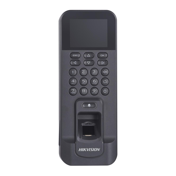
• Operates via Hik-Connect mobile client • NFC tag anti-cloning 3 Appearance Description View the device appearance and the keypad's description. Figure 3-1 Device Appearance Note The pictures here are for reference only. Some models do not support card swiping function. For details, refer to the actual product. - Page 18 Figure 3-2 Keypad Description Table 3-2 Keypad Description Description Exiting Key: Press the button to exit the menu. Note If you enable the attendance status function, the exiting key can be the shortcut key of the attendance status. Direction Keys: Use direction keys to move the cursor in the menu.
-
Page 19: Device Wiring
Description Deleting Key: Press the key to delete the letters or numbers one by one in the textbox. Editing Key: Hold the key to shift among numbers/lowercases, numbers/ uppercases and symbols. 4 Device Wiring 4.1 Terminal Description The terminal diagram are as follows. Figure 4-1 Terminal Diagram... - Page 20 Table 4-1 Wiring with Secure Door Control Unit Description Termin Cable Functio Descri Color Group ption Name 12 VDC +12 V Power Group Power Supply Input Black Yellow/ Alarm Blue Input 1 Alarm Input Yellow/ Black Group Yellow/ Purple Alarm Alarm Yellow/ Output...
-
Page 21: External Device Wiring
Termin Cable Functio Descri Color Group ption Name Tamper Gray TAMP Alarm Wiring Black White/ Purple White/ Lock Yellow Wiring White/ Door Lock Yellow/ SENSO Contac Green t Signal Group Input White/ Black Exit Yellow/ BUTTO Door Grey Wiring White/ BELL+ Doorbe Brown... -
Page 22: Secure Door Control Unit Wiring
Note The external power supply and the access control terminal should use the same GND cable. 4.3 Secure Door Control Unit Wiring The wiring diagram is as follows: Figure 4-3 Secure Door Control Unit Wiring Note • The external power supply and the secure door control unit should use the same GND cable. -
Page 23: Activation
Figure 5-2 Install Mounting Plate 4. Wire the corresponding cables. 5. Align the device with mounting plate. Push the terminal in the mounting plate from bottom up. Fasten the terminal with the buckles on the plate. Figure 5-3 Install Device 6. -
Page 24: Activate Via Device
Before You Start • Get the SADP software from the supplied disk or the official website http://www.hikvision.com/en/ , and install the SADP according to the prompts. • The device and the PC that runs the SADP tool should be within the same subnet. -
Page 25: Activate Device Via Client Software
Caution STRONG PASSWORD RECOMMENDED-We highly recommend you create a strong password of your own choosing (using a minimum of 8 characters, including upper case letters, lower case letters, numbers, and special characters) in order to increase the security of your product. And we recommend you reset your password regularly, especially in the high security system, resetting the password monthly or weekly can better protect your product. -
Page 26: Local Settings
increase the security of your product. And we recommend you change your password regularly, especially in the high security system, changing the password monthly or weekly can better protect your product. Proper configuration of all passwords and other security settings is the responsibility of the installer and/or end-user. 7. - Page 27 Note • The ID refers to the user attendance serial No. • The ID should be between 1 and 99999999 and should not start with 0. • The ID should be used for once. Name Enter the new user name. Note •...
-
Page 28: Local Login
Move the cursor and select Set and select a template from the list. Note For details about editing template, see Set Schedule Template. Auth. Select an authentication mode when verifying user's permission. Note • If you select the authentication mode as Controller, you should set the authentication mode in Set Access Control Parameters. -
Page 29: Communication Settings
Note • Press the up or down key on the keypad to change the input method. • The login page varies depending on different device model. When operation, refer to the actual device page. 7.4 Communication Settings Set device network, EHome, Hik-Connect service, etc. 7.4.1 Set Network You can set the device network parameters, including the IP address, the subnet mask, the gateway address, and the DHCP. -
Page 30: Change Verification Code
7.4.3 Change Verification Code You can change the device verification code before you add the device to the Hik-Connect mobile client. Before You Start Make sure your device has connected to a network. Steps 1. Move the cursor and select Comm. → Mobile-App . 2. -
Page 31: Set Wiegand Parameters
Note • Remember the EHome account and EHome key. You should enter the account name or the key when the device should communicate with other platforms via EHome protocol. • EHome key range: 8 to 32 characters. 7.4.5 Set Wiegand Parameters You are able to set the Wiegand direction (send/receive) and the Wiegand mode (Wiegand 26/Wiegand 34). - Page 32 password, the department, the template, the role and the authentication mode. Steps 1. Move the cursor and select User → New to enter the New page. Figure 7-5 New Page 2. Enter the new user's parameters. ID (Employee ID) By default, the ID No. will be increased in sequence. You can edit the ID according to your preference.
- Page 33 No. manually, you should enable Press Key to Input Card No.. For details, see Configure Parameters for Access Control Device. FP (Fingerprint) On the Fingerprint page, select a target finger and record according to the voice prompt. Note • The same fingerprint cannot be repeatedly added. •...
-
Page 34: Manage Person (Search/Edit/Delete)
Note • All persons can enter the main page by entering the device password to operate if there is no admin user configured. • After configuring the admin, you should authenticate the admin to enter the main page. • You can use the USB interface to import the user information. -
Page 35: Set Access Control Parameters
alarm, and the authentication times exceeded, and the super password. Holiday (Holiday Group) Configure the holiday group for the access control function. In the setting duration, the attendance will be failed and the door cannot be controlled. WK. Plan (Week Plan) Configure the week plan for the access control function. -
Page 36: Set Holiday Group
Parameter Description use multiple authentication modes. • If you adopt multiple authentication modes, you should authenticate other methods before authenticating face. Select the card reader's Sub Reader Auth authentication mode. You can select "Remain Open" or "Remain Closed" according to your Door Contact actual needs. -
Page 37: Set Week Plan
Figure 7-9 Add Holiday Group 3. Add new holiday. 1) Select New ACS Holiday. Figure 7-10 Add New Holiday 2) Set the holiday name, start and end time. 3) Set the holiday period for access. Note Up to 8 periods can be edited. During the holiday time, the attendance will be invalid and the person cannot control the door status. -
Page 38: Set Schedule Template
Figure 7-11 Week Plan List 2. Move the cursor and select New. Figure 7-12 Add New Week Plan 3. Set the week plan's parameters, including the week plan name, the week plan time,a the periods. Note The person can take attendance or control the door status according to the configured week plan. -
Page 39: Attendance Status
Figure 7-14 Add New Template 3. Configure the schedule template parameters, including the template name, the week plan and the holiday group. 4. Press ESC and select Yes to save the settings and exit the page. 5. Optional: You can also search, edit, or delete the template. 7.7 Attendance Status Set attendance mode and choose attendance status. -
Page 40: Set Manual Attendance
marked as check in. And the valid person's authentication after 17:00 on Monday will be marked as check out. 5. Press ESC and save the settings. Result Enter the initial page, the current attendance mode will be displayed on the page. When you authenticate on the initial page, the authentication will be marked as the configured attendance status according to the configured schedule. -
Page 41: Disable Attendance Mode
Before You Start Add at least one person, and set the person's authentication mode. For details, see Person Management. Steps 1. Move the cursor and select System → Att. Status to enter the Attendance Status page. 2. Move the cursor and select Attendance Mode and set the attendance mode as Manual and Auto. -
Page 42: Time And Attendance Management
Figure 7-18 Disable Attendance Mode The attendance status function is disabled, and you will not view or configure the attendance status on the initial page. 7.8 Time and Attendance Management Manage department, shift, holiday, schedule, and report. You can add, edit, delete department/shift/holiday/schedule. You can also export the attendance report. -
Page 43: Shift Management
Search Department Search the target department by entering the department name. Move the cursor to the Dept., and press OK to enter the department list. Enter the department name in the search box, and press OK to start search. Reset Department Reset all parameters of the target department to the default ones. - Page 44 The early leave threshold duration. Note The available time is from 0 to 1440 min. Set Normal Shift Set the normal shift attendance information, including the shift name and the shift period. You can also reset the normal shift after editing. Before You Start Set the attendance rule.
-
Page 45: Manage Holiday (Add/Search/Edit/Delete)
Figure 7-23 Man-Hour Shift Page 2. Select a shift from the list, and press OK . 3. Select Edit to enter the Edit Shift page. Note By default, the man-hour shift type includes 6H/Day (6 hours per day), 8H/Day (8 hours per day), and 30 custom types. 4. -
Page 46: Shift Schedule
Delete Holiday Move the cursor and select Holiday → Holiday to enter the holiday list. Select a holiday and select Delete to delete the holiday. 7.8.5 Shift Schedule Combine shift and holiday according to your actual needs. Scheduling shift by department and scheduling shift by individual are supported. -
Page 47: Export Attendance Report
4. Press ESC and select Yes to save the settings. Schedule Shift by Individual Check in/out according to individual's conditions. Before You Start • Add user before setting schedule shift by individual. For details, see Add Person. • Set the normal shift or the man-hour shift. For details, see Set Normal Shift and Set Man-Hour Shift. -
Page 48: Data Transfer
Note • The supported USB flash drive format is FAT32. • The USB flash drive memory should be from 1G to 32G. Make sure the free space of the USB flash drive is more than 512 M. 2. Move the cursor and select Report. Press OK to enter the Report page. -
Page 49: Basic Settings
Plug a USB flash drive in the device USB interface, and select Export ACS Para. or Export Attendance Data, enter the key, and press OK. The data will be exported to the USB flash drive. Note • The supported USB flash drive format is FAT32. •... -
Page 50: Manage System Data
Select to enable or disable the DST. When the DST is enabled, you can set the DST bias time, the start time and the end time. • D ST Bias: You can select 30min, 60min, 90min and 120min. • S tart: Set the start time of the DST. •... - Page 51 Figure 7-32 System Page 3. Edit the parameters. Time Format Select an appropriate time format according to your preference. Keypad Sound Enable or disable the keypad sound according to your preference. Voice Prompt Enable or disable the voice prompt according to your preference.
-
Page 52: System Upgrade
When the function is enabled, the system will remind you to delete records. The system will delete the first 3000 attendance records when the memory reaches the configured threshold, in order to save the new attendance records. By default, the function is enabled. For details, see Attendance Record Deleting Rule. -
Page 53: Log Query
All parameters, excluding the communication parameters, the remote user management, and events, will restore to the factory parameters. 4. Confirm settings in the prompt page and the device starts restoring. 7.10.6 Log Query You can search the authentication logs via the user's employee ID, name, or card. -
Page 54: Client Software Configuration
Figure 7-36 Device Page 8 Client Software Configuration 8.1 Add Device The client provides three device adding modes including by IP/ domain, IP segment, and ISUP protocol. The client also supports importing multiple devices in a batch when there are large amount of devices to be added. - Page 55 Enter the device password. Caution The password strength of the device can be automatically checked. We highly recommend you change the password of your own choosing (using a minimum of 8 characters, including at least three kinds of following categories: upper case letters, lower case letters, numbers, and special characters) in order to increase the security of your product.
-
Page 56: Add Device By Ip Address Or Domain Name
Caution The password strength of the device can be automatically checked. We highly recommend you change the password of your own choosing (using a minimum of 8 characters, including at least three kinds of following categories: upper case letters, lower case letters, numbers, and special characters) in order to increase the security of your product. -
Page 57: Add Devices By Ip Segment
Enter the device user name. By default, the user name is admin. Password Enter the device password. Caution The password strength of the device can be automatically checked. We highly recommend you change the password of your own choosing (using a minimum of 8 characters, including at least three kinds of following categories: upper case letters, lower case letters, numbers, and special characters) in order to increase the security of your product. -
Page 58: Add Device By Ehome Account
Steps 1. Enter the Device Management module. 2. Optional: Click on the right of Device Management and select Device. The added devices are displayed in the list. 3. Click Add to open the Add window. 4. Select IP Segment as the adding mode. 5. - Page 59 For access control devices supports EHome 5.0 protocol, you can add them to the client by EHome protocol after entering device ID and key, if you have configured their server addresses, port No., and device IDs. Before You Start Make sure the devices have connected to the network properly. Steps 1.
-
Page 60: Import Devices In A Batch
8.1.5 Import Devices in a Batch You can add multiple devices to the client in a batch by entering the device parameters in a pre-defined CSV file. Steps 1. Enter the Device Management module. 2. Click Device tab on the top of the right panel. 3. -
Page 61: Person Management
8. Perform the following operations after adding the devices. Remote Click on Operation column to set Configuration remote configuration of the corresponding device. Note • For some models of devices, you can open its web window. To open the original remote configuration window, press Ctrl and click •... -
Page 62: Configure Basic Information
8.2.2 Configure Basic Information You can add person to the client software one by one and configure the person's basic information such as name, gender, phone number, etc. Steps 1. Enter Person module. 2. Select an organization in the organization list to add the person. -
Page 63: Collect Fingerprint Via Client
Figure 8-1 Issue a Card by Local Mode 6. Set other related parameters. Card Enrollment Station Select the model of the connected card enrollment station. Note Currently, the supported card enrollment station models include DS-K1F100-D8, DS-K1F100-M, DS-K1F100-D8E, and DS-K1F180-D8E. Card Type This field is only available when the model is DS-K1F100-D8E or DS-K1F180-D8E. -
Page 64: Collect Fingerprint Via Access Control Device
PC running the client. The fingerprints recorded can be used as credentials of the persons to access the authorized doors. Before You Start Connect the fingerprint recorder to the PC running the client. Steps 1. Enter Person module. 2. Select an organization in the organization list to add the person and click Add. -
Page 65: Configure Access Control Information
3. In the Credential → Fingerprint panel, click +. 4. In the pop-up window, select the collection mode as Remote. 5. Select an access control device which supports fingerprint recognition function from the drop-down list. 6. Collect the fingerprint. 1) Click Start. 2) Place and lift your fingerprint on the fingerprint scanner of the selected access control device to collect the fingerprint. -
Page 66: Customize Person Information
- Click Add and New to add the person and continue to add other persons. 8.2.7 Customize Person Information You can customize the person properties which are not pre- defined in the client according to actual needs, e.g., place of birth. -
Page 67: Import Person Information
You can import the information of multiple persons to the client software in a batch. Meanwhile, you can also export the person information and save them in your PC. 8.2.10 Import Person Information You can enter the information of multiple persons in a predefined template (a CSV file) to import the information to the client in a batch. -
Page 68: Move Persons To Another Organization
If the added access control device has been configured with person information (including person details, fingerprint, and issued card information), you can get the person information from the device and import them to the client for further operations. Steps Note •... -
Page 69: Report Card Loss
3. Set the card issuing parameters. For details, refer to Set Card Issuing Parameters. 4. Click Initialize to initialize the card enrollment station or card reader to make it ready for issuing cards. 5. Click the card number column and enter the card number. - Place the card on the card enrollment station. -
Page 70: Configure Schedule And Template
Select the model of the connected card enrollment station Note Currently, the supported card enrollment station model is DS- K1F180-D8E. Card Type Select the card type as EM card or IC card according to the actual card type. Buzzing Enable or disable the buzzing when the card number is read successfully. -
Page 71: Add Template
1) Click Add in the Holiday List field. 2) Drag the cursor to draw the time duration, which means in that duration of time, the configured access group is activated. Note Up to 8 time durations can be set to one holiday period. 3) Optional: Perform the following operations to edit the time durations. -
Page 72: Set Access Group To Assign Access Authorization To Persons
5. Edit the week schedule to apply it to the template. 1) Click Week Schedule tab on the lower panel. 2) Select a day of the week and draw time duration(s) on the timeline bar. Note Up to 8 time duration(s) can be set for each day in the week schedule. -
Page 73: Configure Advanced Functions
between card number and fingerprint, linkage between card number and fingerprint, card password, card effective period, etc). 1. Click Access Control → Access Group to enter the Access Group interface. 2. Click Add to open the Add window. 3. In the Name text field, create a name for the access group as you want. -
Page 74: Configure Device Parameters
Note • For the card related functions(the type of access control card), only the card(s) with access group applied will be listed when adding cards. • The advanced functions should be supported by the device. • Hover the cursor on the Advanced Function, and then Click to customize the advanced function(s) to be displayed. - Page 75 Reserved. If enable the function, the device can recognize the ID card. You can present ID card on the device. 4. Click OK. 5. Optional: Click Copy to, and then select the access control device(s) to copy the parameters in the page to the selected device(s).
- Page 76 Create a dismiss code which can be used to stop the buzzer of the card reader (by entering the dismiss code on the keypad). Note • The duress code, super code, and dismiss code should be different. • The duress code, super password, and the dismiss code should be different from the authentication password.
- Page 77 Get card reader type and description. They are read-only. Default Authentication Mode View the default card reader authentication mode. Fingerprint Capacity View the maximum number of available fingerprints. Existing Fingerprint Number View the number of existed fingerprints in the device. 4.
-
Page 78: Configure Remaining Open/Closed
How long the alarm output will last after triggered. 4. Click OK. 5. Optional: Set the switch on the upper right corner to ON to trigger the alarm output. 8.5.2 Configure Remaining Open/Closed You can set the status of the door as open or closed. For example, you can set the door remaining closed in the holiday, and set the door remaining open in the specified period of the work day. -
Page 79: Configure Custom Wiegand Rule
4) Drag the cursor to draw the time duration, which means in that duration of time, the configured access group is activated. Note Up to 8 time durations can be set to one holiday period. 5) Perform the following operations to edit the time durations. •... -
Page 80: Configure Card Reader Authentication Mode And Schedule
5. Set the parity mode according to the property of the third party card reader. Note • Up to 80 bits are allowed in the total length. • The odd parity start bit, the odd parity length, the even parity start bit and the even parity length range from 1 to 80 bit. -
Page 81: Configure Other Parameters
Figure 8-3 Select Card Reader Authentication Mode Note PIN refers to the PIN code set to open the door. Refer to Configure Access Control Information. 2) Check the modes in the Available Mode list and they will be added to the selected modes list. 3) Click OK. - Page 82 After adding the access control device, you can set the device log uploading mode, and create EHome account via wired network. Set Log Uploading Mode You can set the mode for the device to upload logs via EHome protocol. Steps Note Make sure the device is not added by EHome.
- Page 83 Note The port number of the wireless network and wired network should be consistent with the port number of EHome. 8. Select the Protocol Type as EHome and select EHome version. Note If set the EHome version as 5.0, you should create an EHome key for the EHome account.
-
Page 84: Configure Linkage Actions For Access Control
5. Set the baud rate, data bit, the stop bit, parity type, communication mode, working mode, and connection mode in the drop-down list. Note When the connection mode is Connect Access Control Device, you can select Card No. or Person ID as the output type. 6. -
Page 85: Configure Client Actions For Access Event
• Client Actions: When the event is detected, it will trigger the actions on the client, such as the client making an audible warning.. • Device Actions: When the event is detected, it will trigger the actions of a specific device, such as buzzing of a card reader and, opening/closing of a door, .. -
Page 86: Configure Device Actions For Card Swiping
You can set the access control device's linkage actions for the access control device's triggered event. When the event is triggered, it can trigger the alarm output, host buzzer, and other actions on the same device. Steps Note It should be supported by the device. 1. -
Page 87: Configure Device Actions For Person Id
The audible warning of access control device will be triggered. Buzzer on Reader The audible warning of card reader will be triggered. 8. Click Save. When the card (configured in Step 5) swipes on the card reader (configured in Step 6), it can trigger the linked actions (configured in step 7). -
Page 88: Door Control
parameters, including event source and linkage target. 8.7 Door Control In Monitoring module, you can view the real-time status of the doors managed by the added access control device. You can also control the doors such as open/close the door, or remain the door open/closed via the client remotely. -
Page 89: Check Real-Time Access Records
Note The Capture button is available when the device supports capture function. The picture is saved in the PC running the client. For setting the saving path, refer to Set File Saving Path in the user manual of the client software. Result The icon of the doors will change in real-time according to the operation if the operation is succeeded. -
Page 90: View Real-Time Events
All the added devices display on this page. 2. In the Operation column, turn on the switch to enable auto- arming, or click Arm All to arm all the devices. Figure 8-5 Device Arming Control 3. View the arming status of each device in the Arming Status column. - Page 91 The priority of the event that indicates the urgent degree of the event. 3. Optional: Right click the table header of the event list to customize the event related items to be displayed in the event list. Figure 8-7 Customize Event Related Items to be Displayed 4.
-
Page 92: Search Historical Events
Parameters in the user manual of client software for details. 8.8.3 Search Historical Events In the Event Search module of the event center page, you can search the historical events via time, device type, and other conditions according to the specified device type, and then process the events. - Page 93 Note Click Show More to set the event type, card reader type, person name, card no., organization. Group The group of the device that occurred the event. You should set the group as condition only when you select the Device Type as All.
-
Page 94: Time And Attendance
7. Optional: Click Export to export the event log or event pictures to the local PC in CSV format. You can set the saving path manually. 8. Hover the cursor on the related picture, and then click the download icon on the upper-right corner of the picture to download it to the local PC. - Page 95 Work Hour Rate is used to calculate work hours by multiplying it by overtime. When you work for a certain period after end-work time on workday, you will reach different overtime level. You can set different work hour rates (1-10, can be a decimal) for three overtime levels. For example, your valid overtime is one hour (in overtime level 1), and the work hour rate of overtime level 1 is set as 2, then the work hours in the period will be calculated as 2...
- Page 96 4. Custom a name for the holiday. 5. Set the first day of the holiday. 6. Enter the number of the holiday days. 7. Set the attendance status if the employee works on holiday. 8. Optional: Check Repeat Annually to make this holiday setting effective every year.
- Page 97 You can customize the leave type (major leave type and minor leave type) according to actual needs. You can also edit or delete the leave type. Steps 1. Enter the Time & Attendance module. 2. Click Attendance Settings → Leave Type to enter the Leave Type Settings page.
- Page 98 • The attendance data will be written to the third-party database. • During synchronization, if the client disconnects with the third-party database, the client will start reconnection every 30 mins. After being reconnected, the client will synchronize the data recorded during the disconnected time period to the third-party database.
-
Page 99: Add General Timetable
Steps 1. Enter Time & Attendance module. 2. Click Attendance Statistics → Report Display . 3. Set the display settings for attendance report. Company Name Enter a company name to display the name in the report. Attendance Status Mark Enter the mark and select the color. The related fields of attendance status in the report will display with the mark and color. -
Page 100: Add Shift
Each Check-In/Out Each check-in time and check-out time is valid and the sum of all periods between adjacent check-in and check-out time will be recorded as the valid working duration. You need to set Valid Authentication Interval for this calculation method. For example, if the interval between card swiping of the same card is less than the set value, the card swiping is invalid. - Page 101 You can add shift for employees including setting shift period (day, week, month) and the effective attendance time. According to the actual requirements, you can adding multiple timetables in one shift for employees, which requires them to check in and check out for each timetable.
-
Page 102: Manage Shift Schedule
7. Optional: Assign the shift to organization or person for a quick shift schedule. 1) Click Assign. 2) Select Organization or Person tab and check the desired organization(s) or person(s) box. The selected organizations or persons will list on the right page. - Page 103 5. Optional: Enable Multiple Shift Schedules and select the effective time period(s) from the added timetables for the persons. Note This is only available for shift with only one timetable. Multiple Shift Schedules It contains more than one timetables. The person can check in/out in any of the timetables and the attendance will be effective.
- Page 104 Note This is only available for shift with only one timetable. Multiple Shift Schedules It contains more than one timetables. The person can check in/out in any of the timetables and the attendance will be effective. If the multiple shift schedules contains three timetables: 00:00 to 07:00, 08:00 to 15:00 and 16:00 to 23:00.
-
Page 105: Manually Correct Check-In/Out Record
Select normal or overtime level to mark the attendance status for temporary schedule. Timetable Select a timetable from drop-down list. Multiple Shift Schedule It contains more than one timetables. The person can check in/out in any of the timetables and the attendance will be effective. -
Page 106: Add Leave And Business Trip
4. Select the correction date. 5. Set the check-in/out correction parameters. - Select Check-in and set the actual start-work time. - Select Check-out and set the actual end-work time. Note You can click to add multiple check in/out items. At most 8 check-in/out items can be supported. -
Page 107: Calculate Attendance Data
7. Optional: Enter the remark information as desired. 8. Click Save. 9. Optional: After adding the leave and business trip, perform one of the following operations. View Click to view the added attendance handling information in calendar or list mode. Note In calendar mode, you need to click Calculate to get the attendance status of the person in one... -
Page 108: Attendance Statistics
4. Set other conditions, including department, name, person ID and attendance status. 5. Click Calculate. Note It can only calculate the attendance data within three months. 6. Perform one of the following operations. Correct Check- Click Correct Check-in/out to add check- in/out in/out correction. - Page 109 5. Select data source as Original Records on Device or Manual Handling Records. 6. Optional: Click Get Events from Device to get the attendance data from the device. 7. Optional: Click Reset to reset all the search conditions and edit the search conditions again.
-
Page 110: Remote Configuration (Web)
Report Name Enter a name for the report. Report Type Select one report type and this report will be generated. Report Time The time to be selected may vary for different report type. Person Select the added person(s) whose attendance records will be generated for the report. -
Page 111: View Device Information
9.1 View Device Information View and set device name, view device type, serial No., version, relay number, and lock number. Select a device from the Device for Management tab and click → System → Device Information to enter the Device Information page. -
Page 112: Time Management
Result The device password is changed. You should enter the new password on the Device for Management page to reconnect the device. 9.3 Time Management Manage device's time zone, time synchronization, and DST parameters. Time Zone and Time Synchronization On the Device for Management page, select a device and click →... -
Page 113: Configure Rs-485 Parameters
All device parameters will be restored to the default ones. The device should be activated after restoring. Upgrade On the Device for Management page, click Remote Configuration → System → System Maintenance to enter the System Maintenance tab. Select a device type from the drop-down list, click Browse and select an upgrade file from the local computer, and click Upgrade. -
Page 114: Network Parameters Settings
9.7 Network Parameters Settings Set device network parameters, including the NIC type, DHCP, and HTTP. On the Device for Management page, click → Network → Network Parameters to enter the Network Parameters Settings tab. NIC Type Select a NIC type from the drop-down list. You can select either Self-adaptive, 10M, or 100M. -
Page 115: Configure Wi-Fi
After creating the EHome information, you can add the device via EHome protocol. 9.10 Configure Wi-Fi Steps 1. On the Device for Management page, click → Network → Wi-Fi to enter the Wi-Fi Settings tab. 2. Check Enable to enable the Wi-Fi function. 3. -
Page 116: View Relay Status
• Visit the official website of our company. Then go to Support → Tool → Hikvision App Store to download the application according to your mobile phone system. • Scan the QR code below to download the application. -
Page 117: Set Door Open Duration
Figure 10-2 The Icon Representing Door 2. Control the door status. Remain Open Keep the door open. Open Door Open the door for a configurable time period. When the time period expires, the door will close. Note For details about configuring the time period, see Set Door Open Duration . -
Page 118: Change Super Password
4. Tap to confirm the selection. If you tap Open Door in the door control page, the door will open for the configured time duration. Note For details about controlling door status, see Control Door Status. 10.3 Change Super Password The Mobile Client allows you to change the super password of the access control device, which can be used to open all the access control points (e.g., doors), even when the access control point is... - Page 119 The log list will be displayed on the Log section of the page. 2. Perform the following operations. Refresh Log Swipe the log list downward to refresh it. List View All Logs Tap View All Logs to enter the Log page and view all access control device logs.
-
Page 120: Tips For Scanning Fingerprint
A. Tips for Scanning Fingerprint Recommended Finger Forefinger, middle finger or the third finger. Correct Scanning The figure displayed below is the correct way to scan your finger: You should press your finger on the scanner horizontally. The center of your scanned finger should align with the scanner center. -
Page 121: Access Control Capacity
B. Access Control Capacity View the access control data's capacity, including the card permission, door status, card reader authentication mode, and attendance data. Table B-1 Card Permission Maximum Configurable Content Parameters Up to 8 time durations are Week Schedule supported for one week schedule Up to 8 time durations are supported for one holiday... - Page 122 Table B-3 Card Reader Authentication Mode Maximum Configurable Content Parameters Week Schedule Holiday Schedule Holiday Group Schedule Template Table B-4 Attendance Maximum Configurable Content Parameters Department Normal Shift Man-Hour Shift Holiday Holiday Group Schedule by Department Schedule by Individual...
-
Page 123: Attendance Record Deleting Rule
C. Attendance Record Deleting Rule Enable Record Delete Set the percentage of the attendance record over threshold prompt. 1. When the record reaches the threshold, an alarm of the attendance record over limit value will be displayed on device screen. The alarm information is: Log will be full, export the report. -
Page 124: Attendance Report Table
D. Attendance Report Table Enter a short description of your concept here (optional). This is the start of your concept. Description of Attendance Report File Name File Name Rule: Device No. + Report Type.xls Device No.: A serial of numbers from 0 to 8. Report Type: •... - Page 125 Shift Period 1 Period 2 Period 3 Period 4 Shift Start Stop Start Stop Start Stop Start Stop Normal Shift Table: Up to 4 periods can be configured in normal shift configuration. You are able to take attendance according to the configured period.
- Page 126 • SW-EW: Up to 4 periods can be configured. It records the attendance time of each user every day. • Late Duration (min): The start-work attendance time is later than the normal start-work time. • Early Leave Duration (min): The end-work attendance time is earlier than the normal end-work time.
- Page 127 • Early Leave Times: The end-work attendance time is earlier than the normal end-work time. Early leave for no more than once every day. • Early Leave Duration (min): Total time duration for early leave. • Absence Times: Total absence times. •...
-
Page 128: Custom Wiegand Rule Descriptions
E. Custom Wiegand Rule Descriptions Take Wiegand 44 as an example, the setting values in the Custom Wiegand tab are as follows: Custom Wiegand 44 Wiegand Name Total Length Transformation Rule (Decimal byFormatRule[4]=[1][4][0][0] Digit) Parity Mode XOR Parity Odd Parity Start Length Even Parity Length... - Page 129 Even Parity Start Bit, and Length If you select Even Parity, these items are available. If the even parity start bit is 12, and the length is 12, then the system will start even parity calculation from bit 12. It will calculate 12 bits. The result will be in the last bit.
-
Page 130: Communication Matrix And Device Command
Device Command Scan the following QR code to get the device common serial port commands. Note that the command list contains all commonly used serial ports commands for all Hikvision access control and video intercom devices. Figure F-2 Device Command...
Need help?
Do you have a question about the DS-K1T804A Series and is the answer not in the manual?
Questions and answers