Table of Contents
Advertisement
Advertisement
Table of Contents

Related Manuals for Kedacom IPC Series


Summary of Contents for Kedacom IPC Series
- Page 1 KEDACOM User Manual for HD IP Camera of IPC Series V3 (Mar, 2018)
- Page 2 Trademark Kedacom™ and are trademarks of Suzhou Keda Technology Co., Ltd. in China and various other countries. All other trademarks mentioned in this document are the property of their respective holders. Suzhou Keda Technology Co., Ltd. 131 Jinshan Road New District, Suzhou, 215011 People's Republic of China http://www.kedacom.com/en...
- Page 3 Target Audience Administrators and Operators of Video Surveillance Products Document Version Applicable Models IPC1X3 series IPC185 series IPC2X51 series IPC2X52 series IPC2X53 series IPC2255 series IPC2X10 series IPC2X31, IPC2X32 series IPC2X11 series IPC2X40 series IPC2X33 series Related Document Quick Start Guide Convention Icon Convention...
- Page 4 This product is intended to be supplied by a Listed Power Unit, output rated minimum 24Vac, 50/60HZ, 0.5A or 12Vdc, 0.8A or POE,0.5A,non-energy hazards and Tma=60Deg.C. complied with LPS. the function of the ITE being investigated to IEC 60950-1 is considered not likely to require connection to an Ethernet network with outside plant routing, including campus environment;...
-
Page 5: Table Of Contents
Contents Product Brief ............................. 1 Appearance ............................2 Start Up ............................6 Client Installation Conditions ....................6 Initial Configuration ......................6 3.2.1 Modify Parameter ....................... 6 3.2.2 Login Web Client ......................8 3.2.3 Login to the Web Client Interface ................10 3.2.4 Focus ........................ - Page 6 Tampering .......................... 20 *Guard Line ........................21 *Defocus ..........................23 *Scene Change ........................23 *Enter Guard Area ......................24 *Exit Guard Area ........................ 26 *Object Left ........................26 4.10 *Object Removal ........................ 26 4.11 *Gathering .......................... 26 4.12 *Audio Surge ........................26 4.13 *Alarm Linkage ........................
- Page 7 4.19 *Playback ........................... 34 4.19.1 Playback ......................35 4.19.2 Download ......................35 4.20 Upgrade ..........................35 4.20.1 Firmware Upgrade ....................35 4.20.2 Web Client Upgrade ..................... 36 4.20.3 Restoration ......................37 Settings ............................39 Network Access ......................... 39 5.1.1 Ethernet ........................39 5.1.2 PPPoE ........................
-
Page 8: Product Brief
HD IP Camera User Manual Product Brief HD IP Camera (hereinafter referred to as Camera) is a remote video surveillance device based on IP network technology. It encodes and transmits HD video. Some features of the HD IP camera: Live View Apply high-performance progressive scan sensor, with clear image and vivid color;... -
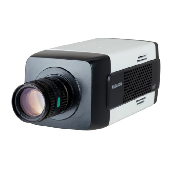
Page 9: Appearance
HD IP Camera User Manual Appearance Picture 2-1 IPC113 / IPC123 / IPC143 series Picture 2-2 IPC185 series Picture 2-3 IPC2251 series Picture 2-4 IPC2451 series... - Page 10 HD IP Camera User Manual Picture 2-5 IPC2255-GN series Picture 2-6 IPC2152 / IPC2252 / IPC2452 series...
- Page 11 HD IP Camera User Manual Note: Different sub-models may have some difference in their appearance. Device appearance is subject to the actual model. Picture 2-7 IPC2253 / IPC2453 series Picture 2-8 IPC2110 / IPC2210 series Picture 2-9 IPC2131 / IPC2132 / IPC2231 / IPC2431 series Picture 2-10 IPC2233 / IPC2433 series...
- Page 12 HD IP Camera User Manual Picture 2-11 IPC2111 / IPC2211 / IPC2411 series Picture 2-12 IPC2140/ 2240 / 2440 series...
-
Page 13: Start Up
Start Up Please refer to the Quick Start Guide in the packing for device installation and wiring. 3.1 Client Installation Conditions Requirements of PC for installing the client: Operating System: Windows XP or newer versions Browser: IE7.0 or later versions, Firefox, Google Chrome (41 and below versions) Processor: 3.3 GHz CORE®i3 series and later version or other equivalent processors RAM Memory: 4GB or above DirectX:9.0c... - Page 14 Picture 3-2 Activate camera Select a camera to be configured, click “Modify Params” or right click the mouse. Interface is shown in Picture 3-3. Modify parameters and fill admin user name (admin) and the password set when activating the device. Picture3-3 Modify Parameter Click “OK”...
-
Page 15: Login Web Client
Picture 3-4 Reboot device 3.2.2 Login Web Client After modification, camera will reboot automatically. Please wait patiently. After reboot, the button will be enabled again. Please select this device again and click “Login” or double click device name to enter web client. Interface is shown in Picture 3-5. - Page 16 Picture 3-6 First login through web client If user enters a wrong user name or password for 3 times, the camera IP will be locked up for 10 minutes, during which user cannot login to this camera. If user forgets the password, reset the password. Click “Password Reset“ and a window will pop up, as shown below.
-
Page 17: Login To The Web Client Interface
Picture 3-8 Password reset 3.2.3 Login to the Web Client Interface Enter user name and password: when login successfully for the first time, download and install the plug-in. Close browser when installing. After finishing, double-click the device in IPCSearch to open browser and enter user name and password. Interface after login is shown below. - Page 18 client and adjust focus till the image is clear. Some models also support other focusing method. Go to Settings > Camera > Image > Focus, and select “Manual” for Focus Mode. Go to Settings > Camera > Image > Focus, select “Continuous Focus” and the camera will focus automatically every time the system triggers focusing.
-
Page 19: Product Functions
Product Functions By the web client, user can not only view live video, but also perform local snapshot and recording. Note: Functions of different cameras may differ, and function with * in this Manual means only some models support. User operation is subject to the actual functions of the model. Disabled button in Web Client means the model doesn’t support the function. - Page 20 Snapshot includes Camera Snapshot and Local Snapshot . User can set picture saving path in Settings > Local Setting. Recording Click this button to start recording and click again to stop recording. Recording is saved on local PC. User can set or modify recording file saving size and path in in Settings > Local Setting.
-
Page 21: Image Adjustment
Click the button to zoom. Left click and drag toward lower right to draw an area. The pixels of this area will be amplified and will cover the whole screen. Left click and drag toward upper left to draw an area, then the image will recover. Double click a point in the image and the point will be centered. -
Page 22: White Balance
Go to Settings > Camera > Image > Exposure, user can set Shutter Mode (Auto/ Manual) and Shutter Lower Threshold or Shutter Level. Increase Gain Camera gain means photo-sensibility, the sensitivity level of a sensor to light. A high gain requires less light exposure for low light condition. Note: However, the higher the gain is, the more noise points there will be and the worse the image will be. -
Page 23: Night Cut
4.1.2.4 Night Cut Day (Night) mode means the image switches to color (B/W), thus to get optimal images for day (sufficient light source) and night (insufficient light source) conditions. Go to Settings > Camera > Image > Night Cut, select Night Cut mode. Select Day from the dropdown list of Night Cut mode and disable IR lamp (only some models support), and the image is colored. -
Page 24: Remote Zoom In
Picture 4-3 Distortion correction The range of “Distortion Sharpen” is 0~100, default 0. Note: When this function is enabled, the max resolution of the main stream is 1080P. When selecting “Standard Mode” under Effect parameters, this function will not be affected. -
Page 25: Defog
4.1.2.8 Defog This function is suitable for outdoor foggy scene and after enabling it, the camera is able to see through the fog. Go to Settings > Camera > Image > Image Enhancement, select “Defog” from the dropdown list of Image Enhancement and drag the slide bar of Defog Sensitivity. -
Page 26: Set Area
Picture 4-7 Motion Detection 4.2.1 Set Area Motion detection supports full area detection and maximum 4 user-defined areas. Go to Settings > Event > Intelligent Function > Motion Detection, and check “Enable”. Click “Clear All” and then “Edit” and the image will be divided into 16 columns and 12 lines of small squares. -
Page 27: Clear Area
toward upper left that contains the defined area, or click the defined squares one by one to clear setting, or click “Clear All” to clear setting. Drag the slide bar to adjust Sensitivity. Click the white bar behind each weekday and drag mouse to make a blue bar as the task duration for that day. -
Page 28: Guard Line
Picture 4-8 Tampering Alarm 4.4 *Guard Line Enable this function in the interface to detect specified area at real time. Once any object enters the guard line, an alarm will be triggered. Go to Settings > Event > Intelligent Function > Guard Line and configure. - Page 29 Picture 4-9 Guard Line Setting steps: Check “Enable”; Select a number from the dropdown list of Guard Line and once one number only. After saving it, user can set another one and max 4 guard lines are allowed; Select a direction from the dropdown list of Guard Line Direction, “A”, “B” or “A&&B”.
-
Page 30: Defocus
Target Filter: to set target area. Click “Edit” and drag the mouse in the scene to draw a rectangle. Click “Stop” after finishing and drag the slide bar of “Max and Min Target Ratio” (1% by default). Moving objects exceeding max and less than min will not trigger an alarm when they pass the guard line(s);... -
Page 31: Enter Guard Area
Picture 4-11 Scene Change Setting steps: Check “Enable”. Drag the slide bar of “Sensitivity” to adjust scene change sensitivity. The larger the number is, the more sensitive the scene change detection is. Duration: Click the white bar behind each weekday and drag mouse to make a blue bar as the task duration for that day. - Page 32 Picture 4-12 Enter Guard Area Setting steps: Check “Enable”; Select a number from the dropdown list of Guard Line and once only one area is allowed. After saving it, user can set another and max 4 guard areas can be set; Target Filter: to set target area.
-
Page 33: Exit Guard Area
the area, and drag the slide bar of “Sensitivity” to set the sensitivity of the guard area to moving objects; Time Threshold: The system will trigger an alarm after the target entering the guard area for a certain period of time, for example 5s. Time threshold can be configured and the default is 5s;... -
Page 34: Alarm Linkage
Drag the slide bar of Voice Intensity Threshold to adjust the detection sensitivity to voice mutation. The higher the Voice Intensity Threshold is, the more sensitive it is to Voice Mutation; Duration: Click the white bar behind each weekday and drag mouse to make a blue bar as the task duration for that day. -
Page 35: Motion Detection Alarm Linkage
Recording Linkage: when an alarm is triggered, start video recording automatically. Need to install a storage card. Text Overlay: when alarm is triggered, display alarm text on screen. Snapshot: when alarm is triggered, capture the image automatically. Need to install a storage card. -
Page 36: Alarm Input Linkage
Click “Save”. 4.13.3 Alarm Input Linkage Camera supports connecting with on-off alarm devices. If the alarm input device is always disabled, when it alarms, the circuit will become a loop and the camera will trigger alarm output by the set alarm linkage type. If the alarm input device is always enabled, when it alarms, the circuit will become open and the camera will trigger alarm output by the set alarm linkage type. -
Page 37: Abnormality Linkage
Picture 4-15 Alarm Input 4.13.4 Abnormality Linkage It is triggered when something abnormal happens. Abnormality includes Disk Full, Disk Error and Internet Disconnected. Picture 4-16 Abnormality Linkage Select Abnormality Type from the dropdown list. Check “Linkage Type”. Click “Save”. -
Page 38: Roi
4.14 Only encode specific area to ensure normal surveillance and constant resolution of key area under poor network. Picture 4-17 ROI 4.14.1 Go to Settings > Camera > Video > ROI, and check “Enable”. Click “Edit”, and drag an area as the clipping area. Select encoding grade from the dropdown list. Click “Save”... -
Page 39: Set
4.15.1 The image is divided into 16 columns and 12 rows of small squares. The maximum number of Privacy Mask area is 4. Go to Settings > Camera > Video > Privacy Mask, and check “Enable”. Click “Edit”, and the image is divided into 16 columns and 12 rows of small squares. -
Page 40: Sdi Output
Picture 4-19 Video info overlay 4.17 *SDI Output For cameras with HD-SDI output function, when the resolution is 1080P, frame rate supports 25 fps, 30 fps, 50 fps and 60 fps; when the resolution is 1080i, frame rate supports 50 fps and 60 fps;... -
Page 41: Snapshot
4.18 *Snapshot Click “Snapshot” to enter snapshot management interface. User can view or download snapshots in SD card (An SD card must be inserted in the camera). Note: If the Snapshot interface is disabled, please confirm the SD card is inserted and then login client again. -
Page 42: Playback
Picture 4-22 Recording 4.19.1 Playback Select recording duration from the calendar. If there is background color on a date, it means there is recording on that day. Select duration of the date and the video will be displayed directly in the right window. -
Page 43: Web Client Upgrade
Picture 4-23 Firmware Upgrade Select local upgrade file (<*.pkg> or <*.img> format). During upgrading, please do nothing but waiting. After upgrading, if it is necessary to upgrade the web client, the system will prompt to download the plug-in. Please refer to the Web Client Upgrade for details. -
Page 44: Restoration
Picture 4-24 Download Plug-in Method 2 After firmware upgrade, please re-login web client. The page will prompt to download a new plug-in control. After downloading, the upgrade is completed. Re-login to enter the latest web client. Note: For detailed operation instructions of Web Client, please refer to the help document. - Page 45 Picture 4-25 Restoration...
-
Page 46: Settings
Settings Some models may not support some of the functions stated below. User operation is subject to the actual models and clients. 5.1 Network Access The part of Initial Configuration has introduced how to modify parameters via IPCSearch to make camera access network. Camera accepts multiple network access methods (via Ethernet and PPPoE). -
Page 47: Register To Vms
5.2 Register to VMS Go to Settings > Network > Access Protocol > VSIP, as shown in Picture 5-3. Enter “VMS Address” and “VMS Port Number”. Click “Save” and reboot device. Picture 5-3 Register to VMS 5.3 BNC Output Camera with BNC output can output analog image directly when local display function is enabled. -
Page 48: User Security
Note: For cameras with HD-SDI output, when BNC is enabled, the web client will stop image output. 5.4 User Security 5.4.1 User Management Go to Settings > System > User Security > User. Add: Click “Add”, and enter user name and password in the popup interface. Select user type from the dropdown list, and assign operation rights to newly added user from the Authorization List. -
Page 49: Security Service
Add Black/White List: After select filter method, click “Add” and input IP address in the popup interface, and click “Confirm”. Modify Black/White List: Select the IP address from the list and click “Modify” to modify the IP address in the popup interface, and click “Confirm”. -
Page 50: Video Encoding
Check the options in “Content” and preview the result in the window below. For example, if user checks “Time”, time will be displayed in the window. Edit positions: drag the items in the window with mouse to change their positions. Edit OSD texts: for example, if user checks OSD1, double click OSD1 textbox and input characters in the popup interface. - Page 51 Picture 5-9 Advanced Configuration Click “Save” and reboot camera to make setting take effect. After reboot, re-login; Go to Settings > Camera > Video > Encoding Format, as shown in Picture 5-10. In Multi-stream option, select Single Stream, Dual-stream, Triple-stream or Quad-stream from the dropdown list, and the selection takes effect after reboot.
-
Page 52: Appendix: Glossary Of Terms
Appendix: Glossary of Terms Term Explanation High Definition QXGA Resolution of 2048*1536 pixels (4:3) UXGA Resolution of 1600*1200 pixels (4:3) 1080P Resolution of 1920*1080 pixels 720P Resolution of 1280*720 pixels Resolution of 352*288 pixels QCIF Resolution of 176*144 pixels Personal Computer Internet Protocol MPEG4 Moving Pictures Experts Group...
Need help?
Do you have a question about the IPC Series and is the answer not in the manual?
Questions and answers