Table of Contents
Advertisement
Quick Links
Included Items
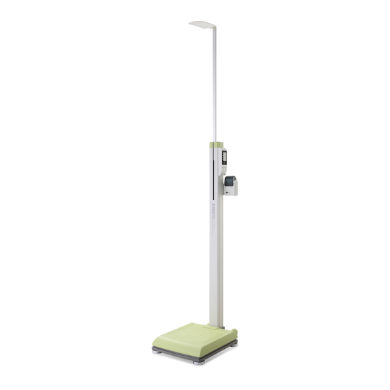
❶ BSM370
❷ Quick Reference
❸ User's manual CD
❹ Adapter (12V, 3.33A) 1EA
❺ Power cord
(AC 250V, 10A, 1.8m( 5ft. 10in.)) 1EA
❻ S crew
❼ Joint cover
Optional
❽ Thermal printer 1EA , Thermal printer base
Screw (M4 × 8) 6EA, Cable (95cm (3ft. 1in.))
❾ Remote control device, Cable (2m (6ft. 7in.),10cm (4in.))
❿ Cable - Y type
❽
❾
Remote control device is provided with thermal printer which is attached on.
NOTE
2. Raise the stand of the BSM370
❶ Raise the stand of the BSM370 carefully until it stands upright.
Tighten the joint screw connecting stand body and foot plate.
In case of a loose connection between the stand body and the foot plate,
measurement process cannot be performed properly.
CAUTION
Fix the stand perpendicular on the foot plate.
❷ After the upper part of the BSM370 is fixed,
close the joint cover.
4. Balance the BSM370
Use the bubble level indicator on the BSM370 to check it is level. Use the
leveling screw underneath the foot plate of the BSM370 if it is not level.
Bubble level indicator
Leveling screw
<Un-leveled state>
<Leveled state>
If the equipment is not horizontally level, adjust the leveling screw on the
opposite side of the bubble to place it at the center of the level indicator.
NOTE
Quick Reference
❶
❷
❸
❹
❺
❻
❼
❿
<Raising>
<Lowering>
Workplace requirements
Location: Indoor use only. Any outdoor area where the equipment is to be
•
located should meet all the conditions below.
Operation environment: 10~40 ℃ (50~104
•
Adapter: Power Input 100~240V, 50/60Hz, 1.2A
•
Power Output DC 12V, 3.33A
Please check the height from the ground to the ceiling before installing
BSM370. It should be at least as tall as 2156mm ( 84.9in.).
CAUTION
BSM370's height is 2126mm (83.7in.).
Note on Unpacking & Assembling
(1) Place the BSM370 on level ground.
(2) Do not move by holding the head bar or operation part with LCD.
1. Open the box
Open the packing box and remove the wrapping.
Take out all contents.
Save the wrapping material after unpacking in the event of relocation.
NOTE
3. Fixed the head bar
Unscrew the fixed screw at the head bar
part and uplift it by 90 degree.
Screw tightly.
Do not lift the head bar to prevent any malfunctioning.
WARNING
5. Power Connection
❶ Connect the power adapter for the BSM370 which is placed on the
back of the foot plate.
Make sure you use the power adapter and main cable provided by
InBody.
WARNING
❷ Turn on the power switch. The head bar will move up automatically.
Head bar of BSM370 will be automatically went up after turning the
device on.
Be careful not to put any weight on the foot plate. If you step on the foot plate
or put a heavy object on the foot plate, it will affect the calibration and
CAUTION
measurements will not be accurate.
When pressure or weight is applied to the foot plate during self-calibration,
message appears. Turn the BSM370 off and on again after removing
NOTE
the material from the foot plate. Please do not apply pressure or weight to the
foot plate during self-calibration.
), 30~75%RH, 70~106kPa
℉
screw
Advertisement
Table of Contents

Subscribe to Our Youtube Channel
Related Manuals for inbody BSM 370


Summary of Contents for inbody BSM 370
- Page 1 Make sure you use the power adapter and main cable provided by Bubble level indicator InBody. WARNING ❷ Turn on the power switch. The head bar will move up automatically. Head bar of BSM370 will be automatically went up after turning the device on.
- Page 2 Website: https://www.inbody.com E-mail: info@inbody.com by pressing the ‘ENTER’ button. InBody reserves the right to modify the dimensions or exterior of BSM370 to improve the The default measurement mode is set as BMI when the system is quality of the products, without consent of the customer.
Need help?
Do you have a question about the BSM 370 and is the answer not in the manual?
Questions and answers