Advertisement
phyCORE
-STM32MP1
®
phyBOARD
-Sargas / SBC Kit
®
Get your phyCORE-STM32MP1 / SBC Kit powered up and connected
in just a few simple steps.
1 | PREPARING THE HARDWARE
1. Have the included connection cables on hand: two USB-A to USB-B Micro cables,
a standard Ethernet cable and the 24 V power adapter (+24 V / 1 A).
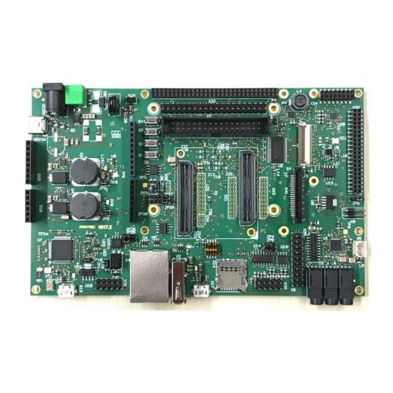
2. Insert the micro SD Card into the uSD Card connector (X14).
3. Set the DIP-Switch (S7) to SD Card (Figure 1).
4. Power up the phyCORE-STM32MP1 by connecting the power adapter (+24 V DC)
to the power supply connector (X9).
F igur e 1:
Boot Switch (S7) SD Card Setting
p hy B OA R D
-S ar ga s
®
with phyCORE
-STM32MP1
®
C O NNEC T O R S
Germany
France
PHYTEC Messtechnik GmbH
PHYTEC France SARL
D-55129 Mainz
F-72140 Sillé le Guillaume
t +49 6131 9221-32
t +33 2 43 29 22 33
f +49 6131 9221-33
f +33 2 43 29 22 34
www.phytec.de
www.phytec.fr
www.phytec.eu
USA
India
PHYTEC America LLC
PHYTEC Embedded Pvt. Ltd.
Bainbridge Island, WA 98110
Bangalore
t +1 206 780 9047
560102
f +1 206 780 9135
t +91 80 40867046
www.phytec.com
www.phytec.in
China
PHYTEC Information Technology Co. Ltd.
Nanshan District, Shenzhen
518026 PRC
t +86 755 6180 2110
www.phytec.cn
Kit Contents
phyBOARD-Sargas + phyCORE-STM32MP1
PCM-068-025113I.A0
L ED s | J U M P ER S / SW I TC HE S
Quick
Quick
Start
Start
Guide
Guide
Power Adapter +24 V
2x5 header to
DB-sub 9 male (x2)
Ethernet Cable
USB flash drive
with Virtual Machine
Micro Cables (2x)
SD Card
USB-A to USB-B
Advertisement
Table of Contents

Subscribe to Our Youtube Channel
Related Manuals for Phytec phyCORE-STM32MP1


Summary of Contents for Phytec phyCORE-STM32MP1
- Page 1 2. Insert the micro SD Card into the uSD Card connector (X14). 3. Set the DIP-Switch (S7) to SD Card (Figure 1). 4. Power up the phyCORE-STM32MP1 by connecting the power adapter (+24 V DC) to the power supply connector (X9).
- Page 2 • Set the DIP-Switch (S7) to UART/USB (Figure 2) • Power up the phyCORE-STM32MP1. The RED LED on the SOM should start blinking RED 2. Plug the second micro-AB USB into the USB OTG connector (X12) and your host PC (that F igur e 2 : contains the BSP image).
Need help?
Do you have a question about the phyCORE-STM32MP1 and is the answer not in the manual?
Questions and answers