Advertisement
phyCORE
-i.MX 8M
®
Azure Edge / AI Kit
Get your Edge Computing / AI Kit powered up and connected
in just a few simple steps.
P R EPA R I N G T H E H A R DWA R E
1. Connect the following components and cables (found in your kit):
• Connect camera assembly via ribbon cable to CSI-1 (X10) (Figure A)
• Screw camera lens into camera assembly (Figure B)
• Connect the Ethernet cable to your preferred Ethernet source and X1
• Insert the SD card into the SD card slot. Ensure the boot jumper is set to SD Card (Figure C).
2. Connect a USB cable to your host PC and the Debug FTDI (X30)
3. Connect display adapter and display to board
(see enclosed documentation LAN-085e.A0 Connecting the Touchscreen to i.MX 8M)
4. Connect the +24 V power adapter (SV042) to power up the kit and begin the booting process.
Please note that all cable and devices need to be connected for the demo to function properly.
F igur e A :
Connecting the Camera Assembly
1
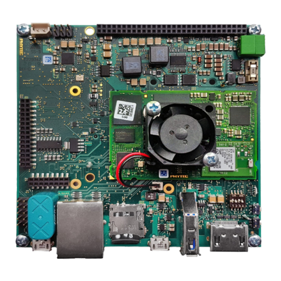
p hy B OA R D
- Polari s
®
with phyCORE
®
-i.MX 8M
F RO N T
Germany
France
PHYTEC Messtechnik GmbH
PHYTEC France SARL
D-55129 Mainz
F-72140 Sillé le Guillaume
t +49 6131 9221-32
t +33 2 43 29 22 33
f +49 6131 9221-33
f +33 2 43 29 22 34
www.phytec.de
www.phytec.fr
www.phytec.eu
USA
India
PHYTEC America LLC
PHYTEC Embedded Pvt. Ltd.
Bainbridge Island, WA 98110
Bangalore
t +1 206 780 9047
560102
f +1 206 780 9135
t +91 80 40867046
www.phytec.com
www.phytec.in
2
3
China
PHYTEC Information Technology Co. Ltd.
Nanshan District, Shenzhen
518026 PRC
t +86 755 6180 2110
www.phytec.cn
Kit Contents
phyBOARD-Polaris with phyCORE-i.MX 8M
PB-02820-001.A1
Color Camera with Sensor Board
(VM-016-COL-M-M12.A1)
F igur e B :
Camera Assembly
Camera
Assembly
(Backside)
B AC K
Quick
Quick
Guide
Guide
USB-A to USB-B Micro Cable
(WK345)
Camera Ribbon Cable (WK114)
Ethernet Cable
(WK114)
Figure C:
SD Boot Mode
Start
Start
Power Adapter 24 V
(SV055)
10" LVDS Display Kit
(KPEB-AV-10-100.A0)
Advertisement
Table of Contents

Subscribe to Our Youtube Channel
Related Manuals for Phytec phyCORE-i.MX 8M


Summary of Contents for Phytec phyCORE-i.MX 8M
- Page 1 -i.MX 8M ® Kit Contents Azure Edge / AI Kit phyBOARD-Polaris with phyCORE-i.MX 8M USB-A to USB-B Micro Cable Power Adapter 24 V PB-02820-001.A1 (WK345) (SV055) Get your Edge Computing / AI Kit powered up and connected in just a few simple steps.
- Page 2 This displays the result of the AI analysis and how confident the analysis is. 2 | TRY THE DEMO The PHYTEC Azure Edge / AI kit enables you to work with the latest AI functionalities in the Microsoft Azure environment. The kit comes with a camera module and a pre- installed connection to the Microsoft Azure cloud.
Need help?
Do you have a question about the phyCORE-i.MX 8M and is the answer not in the manual?
Questions and answers