Table of Contents
Advertisement
Quick Links
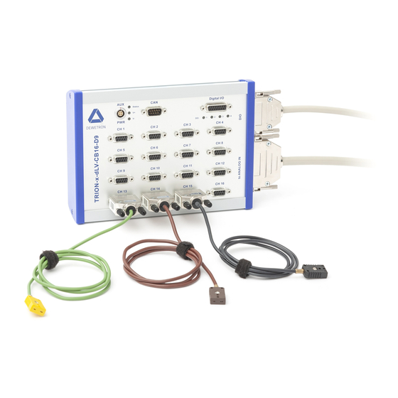
TRION-x-dLV-CB16-D9 / MSI series
TECHNICAL REFERENCE MANUAL
WELCOME TO
THE WORLD OF
DEWETRON!
Congratulations on your new device! It will
supply you with accurate, complete and
reproducible measurement results for your
decision making.
Look forward to the easy handling and the
ISO9001
flexible and modular use of your
DEWETRON product and draw upon more
than 30 years of DEWETRON expertise in
measurement engineering.
EN ISO 14001
THE MEASURABLE DIFFERENCE.
Advertisement
Table of Contents

Related Manuals for Dewetron MSI Series


Summary of Contents for Dewetron MSI Series
- Page 1 Look forward to the easy handling and the ISO9001 flexible and modular use of your DEWETRON product and draw upon more than 30 years of DEWETRON expertise in measurement engineering. EN ISO 14001 THE MEASURABLE DIFFERENCE.
- Page 2 Copyright © DEWETRON GmbH This document contains information which is protected by copyright. All rights are reserved. Reproduction, adaptation, or translation without prior written permission is prohibited, except as allowed under the copyright laws. All trademarks and registered trademarks are acknowledged to be the property of their owners.
-
Page 3: Preface
This guide includes important startup notes, as well as safety notes and information about keeping your DEWETRON system in good working condition over time. However, this manual cannot and is not intended to replace adequate training. -
Page 4: Trion-X-Dlv-Cb16-D9 Specifications
Preface TRION-x-dLV-CB16-D9 specifications TRION-x-dLV-CB16-D9 Sensor excitation – Voltage ±5V ±0.2%; balance around GND; remote sense support – Maximum current 40 mA per channel – Protection Continuous short to ground; short circuit limit is 70 mA Auxiliary sensor supply Depending on external power supply; maximal 4 A –... -
Page 5: Table Of Contents
General MSI functionality ........ 15 Simplified power schematic ........16 Dimensions* ............17 Optional accessory ..........17 Signal connection ......19 Direct signal connection ........19 Voltage ............. 19 Potentiometric sensor ........20 TRION-x-dLV-CB16-D9 / MSI series • Technical reference • Printing version 1.0.5 • March 17, 2021... - Page 6 TABLE OF CONTENTS...
-
Page 7: Safety
Failure to comply with these precautions or with specific warnings elsewhere in this manual violates safety standards of design, manufacture, and intended use of the product. DEWETRON GmbH assumes no liability for the customer’s failure to comply with these requirements. -
Page 8: Electrical Safety Instructions
Safety Electrical safety instructions ` With this product, only use the power cable delivered or defined for the host country. ` DO NOT connect or disconnect sensors, probes or test leads, as these parts are connected to a voltage supply unit. ` The system is grounded via a protective conductor in the power supply cord. -
Page 9: Safety Notices During Operation
` DO NOT use the system in rooms with flammable gases, fumes or dust or in adverse environmental conditions. ` Direct exposure of any DEWETRON product to strong sunlight or other heat radiation shall be prevented, as this could excessively heat up the product and lead to permanent damage of the product. -
Page 10: Notices
Safety Notices NOTICE This text indicates situations or operation errors which could result in property damage or data loss. INFORMATION This text indicates important information or operating instructions. Not observing these instructions could inhibit or impede you from successfully completing the tasks described in this documentation. Symbols Denotes a warning that alerts you to take precautions to avoid injury. -
Page 11: General Information
This product has been classified as Monitoring and Control equipment, and is outside the scope of the 2011/65/EU RoHS Directive. This product is known to contain lead. Warranty information A copy of the specific warranty terms applicable to your DEWETRON product and replacement parts can be obtained from your local sales and service office. Legal information Restricted rights legend Use Austrian law for duplication or disclosure. -
Page 12: Printing History
Printing history Refer to the page bottom for printing version. Copyright © DEWETRON GmbH This document contains information which is protected by copyright. All rights are reserved. Reproduction, adaptation, or translation without prior written permission is prohibited, except as allowed under the copyright laws. -
Page 13: System Setup
There is a 4 A self-resetting fuse for every channel row: CH 1 to 4, CH5 to 8, CH9 to 12, CH 13 to 16. Tab. 2: Connections and ports TRION-x-dLV-CB16-D9 TRION-x-dLV-CB16-D9 / MSI series • Technical reference • Printing version 1.0.5 • March 17, 2021... - Page 14 SyStem SetuP Element Description Status indicator LEDs – Green: Application software connected – OFF: Not connected V+, V- – Green: ±5 V MSI supply OK – OFF: ±5 V MSI supply missing or overload CAN interface con- Pin assignment nector 1.
-
Page 15: Connection With Msis
For traceability, important data, such as serial number or calibration date, are also read out and if necessary addition- ally stored with the measurement data file. TRION-x-dLV-CB16-D9 / MSI series • Technical reference • Printing version 1.0.5 • March 17, 2021... -
Page 16: Simplified Power Schematic
SyStem SetuP Simplified power schematic Fig. 2: Simplified power schematic... -
Page 17: Dimensions
SyStem SetuP Dimensions* *) Dimensions in mm (1 inch = 25.4 mm) Fig. 3: Dimensions Optional accessory Wall mounting assembly: CB16-D9-WALLMOUNT Fig. 4: Wall mounting assembly TRION-x-dLV-CB16-D9 / MSI series • Technical reference • Printing version 1.0.5 • March 17, 2021... - Page 18 SyStem SetuP Notes...
-
Page 19: Signal Connection
Mode Voltage +5 V EXC EXC+ Range Input type Differential GNDi GNDi -5 V EXC EXC- housing Fig. 6: Different output sensor powered by TRION module TRION-x-dLV-CB16-D9 / MSI series • Technical reference • Printing version 1.0.5 • March 17, 2021... -
Page 20: Potentiometric Sensor
SiGnal connection Single-ended sensor powered by the TRION module D-SUB Sensor with Simplified schematic CONNECTOR differential output Mode Voltage EXC+ EXC+ Range Input type Differential GNDi GNDi EXC- EXC- housing Fig. 7: Single-ended sensor powered by the TRION module Potentiometric sensor D-SUB Potentiometer Simplified schematic TRION-x-dLV-CB16-D9... -
Page 21: Signal Connection Using Msi
12.5 50 kS/s -16.1 100 kS/s -15.6 200 kS/s -15.1 100 dB @ 100 Hz Typcial CMRR 60 dB @ 10 kHz Tab. 4: Signal connection MSI-BR-V-200 TRION-x-dLV-CB16-D9 / MSI series • Technical reference • Printing version 1.0.5 • March 17, 2021... - Page 22 SiGnal connection Isolated Sensor MSI-BR-V-200 Simplified schematic TRION-x-dLV-CB16-D9 Self powered sensor Battery measurement Sense+ 22 pF Mode Voltage Sensor with differential +5 V EXC output EXC+ 20 kΩ Range 200 V 1 MΩ SHIELD 1 MΩ 20 kΩ 22 pF EXC- -5 V EXC Sense-...
-
Page 23: Msi2-V-600
15.7 50 kS/s 15.0 100 kS/s 14.6 200 kS/s 14.1 74 dB @ 100 Hz Typcial CMRR 50 dB @ 10 kHz Tab. 5: Signal connection MSI2-V-600 TRION-x-dLV-CB16-D9 / MSI series • Technical reference • Printing version 1.0.5 • March 17, 2021... - Page 24 SiGnal connection AC/DC MSI2-V-600 Simplified schematic PU[REC] voltage Sense+ 100 pF Mode Voltage +5 V EXC EXC+ 10 kΩ Range 1000 V 2.5 MΩ SHIELD 2.5 MΩ 10 kΩ 100 pF EXC- -5 V EXC Sense- Fig. 10: Signal connection MSI2-V-600 CAUTION Risk of injury Voltage measurement up to 600 V must only be carried out with safety banana plug cords.
-
Page 25: Msi2-Stg
The signal is immediately amplified by a factor of 50. This reduces the impact of electromagnetic disturbances by the same factor. The maximum cable length between MSI and the TRION is 50 meters. TRION-x-dLV-CB16-D9 / MSI series • Technical reference • Printing version 1.0.5 • March 17, 2021... - Page 26 SiGnal connection up to 50 m Sensor MSI2-STG Fig. 11: MSI2-STG cable length Isolated Sensor MSI-BR-V-200 Simplified schematic TRION-x-dLV-CB16-D9 Self powered sensor Battery measurement Sense+ 22 pF Mode Voltage Sensor with differential +5 V EXC output EXC+ 20 kΩ Range 200 V 1 MΩ...
- Page 27 7. MSI2-STG is detected automatically. Sensor scaling can be applied. INFORMATION For more information refer to chapter MSI in OXYGEN on page 43. The sensor is now connected. TRION-x-dLV-CB16-D9 / MSI series • Technical reference • Printing version 1.0.5 • March 17, 2021...
- Page 28 SiGnal connection Full bridge 6-wire 10 V 5 V Strain gauge sensor MSI2-STG Simplified schematic TRION-x-dLV-CB16-D9 Sense+ Mode Bridge +5 V EXC 120 Ω 350 Ω Range 10 mV/V EXC: -5 V EXC 10 V (±5 V) Sense- Housing Fig. 14: Full bridge 6-wire Full bridge 4-wire 10 V 5 V Strain gauge sensor...
- Page 29 Mode Bridge +5 V EXC 120 Ω 350 Ω Range 10 mV/V EXC: -5 V EXC 10 V (±5 V) Sense- Housing Fig. 17: Quarter bridge 3-wire TRION-x-dLV-CB16-D9 / MSI series • Technical reference • Printing version 1.0.5 • March 17, 2021...
-
Page 30: Msi-Br-Acc
SiGnal connection MSI-BR-ACC IEPE® MSI-BR-ACC Input range ± 10V Sensor excitation 4 mA ±10 % Compliance voltage >23 V Accuracy 30 Hz to 30 kHz: 0.2 % Power consumption Max. 380 mW Input coupling AC 1.4 Hz Bandwidth 70 kHz limited by TRION-1802 DC accuracy ±0.2 % of reading ±5 μV/V Bandwidth (-3 dB) -
Page 31: Msi2-Ch-X
Sensor connection TEDS For adapter identification Tab. 8: Signal connection MSI2-CH-x Charge sensor MSI2-CH-x TRION-x-dLV-CB16-D9 Mode Charge Range 5000 pC SHIELD 50 Ω 1 MΩ Fig. 19: Signal connection MSI2-CH-x TRION-x-dLV-CB16-D9 / MSI series • Technical reference • Printing version 1.0.5 • March 17, 2021... -
Page 32: Msi2-Th-X
SiGnal connection MSI2-TH-x Thermocouple MSI2-TH-x Thermocouple types Type K, J, T, C Sensor connection 1 m cable with standard miniature thermocouple connector according to TC type Preamplifier Integrated; cable drive capability 50 m Open thermocouple detection 100 MΩ pullup; broken sensor shows positive full scale CJC accuracy 1.0 °C Input impedance... - Page 33 Tab. 10: Accuracy incl. CJC error Functional description The MSI2-TH-x series is the improved version of the previous MSI series. The accuracy is approximately 3 times higher than at the previous version. A calibrated high precision cold junction compensation is included in the adapter. It comes with an integrated preamplifier that boosts the tiny thermocouple voltage up to a few volts.
-
Page 34: Msi-Br-Rtd
SiGnal connection MSI-BR-RTD ` Support of Pt100, Pt200, Pt500, Pt1000, Pt2000 ` 2-, 3- or 4 wire connection MSI-BR-RTD Supported sensors Resistance, Pt100, Pt200, Pt500, Pt1000, Pt2000 Temperature range -200 °C to 850 °C Constant current 1.25 mA Constant current accuracy ±0.02 % from calibrated value Constant current drift 22 ppm/ °C... - Page 35 +5 V Mode Temperature 4 mA Sensor type Pt100 -200 to 850 °C Range -328 to 1562 °F 1 kΩ -5 V Fig. 24: RTD 3-wire sensor TRION-x-dLV-CB16-D9 / MSI series • Technical reference • Printing version 1.0.5 • March 17, 2021...
- Page 36 SiGnal connection RTD 2-wire sensor Pt100 MSI-BR-RTD TRION-x-dLV-CB16-D9 +5 V Mode Temperature 4 mA Sensor type Pt100 -200 to 850 °C Range -328 to 1562 °F 1 kΩ -5 V external solder bridge Fig. 25: RTD 2-wire sensor...
-
Page 37: Msi2-Lvdt
Gain potentiometer DO NOT JUMPER H M L THESE PINS! H = 18 kHz M = 5 kHz L = 2.5 kHz Fig. 26: Sensor connector MSI2-LVDT (1) TRION-x-dLV-CB16-D9 / MSI series • Technical reference • Printing version 1.0.5 • March 17, 2021... - Page 38 SiGnal connection LVDT MSI2-LVDT TRION-x-dLV-CB16-D9 EXC1 2.5/5/18 kHz Mode LVDT EXC2 Range VA - VB VA + VB Gain Fig. 27: Sensor connector MSI2-LVDT (2) Connecting a sensor In order to connect a sensor proceed as follows: 1. Check the sensor datasheet and determine the correct connection. 2.
- Page 39 8. Fine adjust sensor with sensor scaling. INFORMATION For more information refer to chapter MSI in OXYGEN on page 43. The sensor is now connected. TRION-x-dLV-CB16-D9 / MSI series • Technical reference • Printing version 1.0.5 • March 17, 2021...
-
Page 40: Msi2-La-250R-20Ma
SiGnal connection MSI2-LA-250R-20mA 4 to 20 mA sensor MSI2-LA-250R-20mA Supported sensors 4 to 20 mA, loop powered sensors Sensor connection Push-in spring connection, 0.14 to 0.5 mm², AWG 26 to 20 Input range ±25 mA Accuracy 0.05 % of reading ±4 μA Excitation voltage AUX power, refer to simplified power schematic Shunt resistor... - Page 41 AUX power input connector LEMO 1B MSI2-LA-250R-20mA TRION-x-dLV-CB16-D9 Current output sensor AUX PWR Mode Current AUX PWR Range 25 mA 250 Ω Fig. 30: Current output sensor TRION-x-dLV-CB16-D9 / MSI series • Technical reference • Printing version 1.0.5 • March 17, 2021...
- Page 42 SiGnal connection Notes...
-
Page 43: Msi In Oxygen
When the MSI is connected to the device it will get detected and displayed in the Data Channel List. The plugged-in MSI is displayed in the Overview and the mode, range etc. are applied accordingly (see Fig. 31: OXYGEN overview). Fig. 31: OXYGEN overview TRION-x-dLV-CB16-D9 / MSI series • Technical reference • Printing version 1.0.5 • March 17, 2021... - Page 44 mSi in oXyGen This behavior can also be seen for other MSI types (see Fig. 32: Automatic detection of MSIs in OXYGEN). Fig. 32: Automatic detection of MSIs in OXYGEN By clicking on the small gear button of the channel (see Fig. 33: Channel settings), the channel settings can be opened. Since all the according information is set automatically for MSIs, limited settings are available here, depending on the type of MSI (see the examples below).
- Page 45 INFORMATION For a detailed explanation of the OXYGEN software and other software functionalities refer to the OXYGEN Technical Reference Manual available on our website (www.dewetron.com) or the CCC portal (https://ccc. dewetron.com). TRION-x-dLV-CB16-D9 / MSI series • Technical reference • Printing version 1.0.5 • March 17, 2021...
- Page 46 mSi in oXyGen Notes...
-
Page 47: Maintenance And Service
Austria have a very large and professional conference and seminar center, where training classes are conducted on a regular basis starting with sensors and signal conditioning, A/D technology and software operation. Dewetron Inc. in the USA also has a dedicated training facility connected to its headquarters, located in Rhode Island. For more information about training services visit https://www.dewetron.com/academy. -
Page 48: Support
Service and repairs Only the team of DEWETRON is allowed to perform any kinds of repairs to your system to assure a safe and proper op- eration in future. For information regarding service and repairs please contact your local distributor first or DEWETRON directly. -
Page 49: Certificate Of Conformity
EN 55011 Class B Immunity EN 61000-6-2 Group standard Graz, August 23, 2019 Place / Date of the CE-marking Ing. Thomas Propst / Manager Total Quality TRION-x-dLV-CB16-D9 / MSI series • Technical reference • Printing version 1.0.5 • March 17, 2021... - Page 50 CERTIFICATE OF CONFORMITY Notes...
Need help?
Do you have a question about the MSI Series and is the answer not in the manual?
Questions and answers