Table of Contents
Advertisement
Quick Links
Original instructions
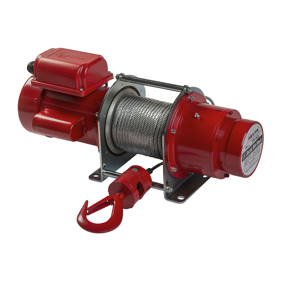
OPERATIONS MANUAL
ELECTRIC WINCHES 230/400 VOLT
[CP.0.DPS / DPT series]
CP.0.DPS SERIES 230 VOLT
CP.0.DPT SERIES 400 VOLT
All of the information reported herein is based on data available at the moment of
NOTE:
printing. We reserve the right to modify our own products at any moment without
notice. Please read the operating instructions carefully before using this product.
Always keep a copy of this instruction manual at hand. Failure to read and comply
with the contents of this manual can result in serious body injury or death, and
property damage.
THIS IS THE SAFETY ALERT SYMBOL. WHEN YOU SEE THIS SYMBOL
ON YOUR
PRODUCTS OR IN THIS MANUAL, BE ALERT FOR
DANGEROUS SITUATIONS.
FOLLOW RECOMMENDED AND SAFE
OPERATING INSTRUCTIONS AT ALL TIMES.
If any doubt remains, please contact your supplier.
Advertisement
Table of Contents

Summary of Contents for Delta CP.0.DPS Series
- Page 1 Original instructions OPERATIONS MANUAL ELECTRIC WINCHES 230/400 VOLT [CP.0.DPS / DPT series] CP.0.DPS SERIES 230 VOLT CP.0.DPT SERIES 400 VOLT All of the information reported herein is based on data available at the moment of NOTE: printing. We reserve the right to modify our own products at any moment without notice.
- Page 2 PRECAUTION – SAFETY WARNINGS The user of the electric pulling winch must always check if guidelines are followed, which you can find in this manual. Also he/she needs to understand the manual and user instructions completely for safety purposes. Please note that if not followed or understood correctly, potential risks are even greater and can lead to severe injuries or equipment damage.
-
Page 3: Table Of Contents
CONTENTS Introduction Page 4 Mark definition Page 4 Safety instructions Page 4 General rules Page 4 Check before operation Page 5 Warnings during operation Page 5 Finished operation Page 6 Inspection and maintenance Page 6 Technical data Page 6 Operation condition and environment Page 6 Technical parameters Page 7... -
Page 4: Introduction
INTRODUCTION electric pulling winches are designed for pulling and lifting load in a safe working environment. The user is responsible for correct operation and must always make sure that the load weight doesn't exceed the rated capacity. If used for lifting purposes, please contact a professional and carry out a risk analysis. -
Page 5: Check Before Operation
2.2 Check before operation This manual is formulated for winch operators. Before the operator start to work, he should know all the contents of safety and operation instructions. If the CAUTION products has deformation or cracks problem on the hook, wire rope, winch please do not use, You should contact your dealer and change parts, please do not use any non-spare parts. -
Page 6: Finished Operation
2.4 Finished operation After operation, please make sure the weight is completely resting on a flat WARNING service to avoid the load from dropping. When the operation finished, cut off the control pendant in order to avoid WARNING wrong operations by others. Emergency procedure: In the event of a blocked steel wire or any other malfunction of electric pulling winch, immediately stop the... -
Page 7: Technical Parameters
3.2 Technical parameters 3.2.1 electric pulling winch specifications Model DPS-200 DPS-250 DPS-300 DPS-500 Capacity (kg) Pulling range (m) Standard Control cable (m) 230V 230V 230V 230V Operation voltage / single phase Cycle (hz) 50 Hz 50 Hz 50 Hz 50 Hz 1500 Power output (watt) 14.1... -
Page 8: Electric Winch Capacity Per Layer
3.2.2 electric pulling winch capacity per layer... -
Page 9: Electric Winch Dimensions
3.2.3 electric winch dimensions Model DPS-200 DPS-250 DPS-300 DPS-500 DPT-30075 DPT-30151 DPT-30375 DPT-30750 DPT-31500 DPT-34000... -
Page 10: Main Characteristics
3.3 Main Characteristics DPS / DPT winches are suitable for pulling applications. If used for lifting purposes, please contact a professional and carry out a risk analysis. Also any modifications made on the electric pulling winch is the sole responsibility of the user / owner. will not be responsible for any problems caused by modifications, wrong use, or any other abnormal situation. -
Page 11: Safe Operation
4. Safe operation 4.1 Declaration Exceeding the rated capacity of the electric pulling winch will lead to dangerous situations. Before operation, please read all the contents of this manual, please make sure that you understand all items, if so then you may operate the winch. Before operating the electric winch, please make sure the work space, structures meet all the safety requirements. -
Page 12: Installation
5. Installation 5.1 Pre installation check CAUTION Check electric winch for transit damage. Check that all fasteners and joints on the electric winch are tight and WARNING secure. Always make sure that the capacity of the bottom hooks corresponds with the WARNING electric winch. -
Page 13: Mounting Holes Of Electric Winch
5.3 Initial lubrication The following lubrication guidelines must be carried out before the electric winch is put into use. (or use an equivalent.) Model DPS.200 DPS.250 DPS.300 DPS.500 DPT.30075 Lifting capacity (kg) Duty Cycle Voltage (v) IP rating Lubricant of gearbox Recommended SHELL Gadus S3 V220C 2 grease or equilavant Lubricant quantity gearbox 0.5 lt... -
Page 14: Operation
6. Operation 6.1 Selection and qualification of operating personnel For independent operation or maintenance of electric puling winch, the operator must meet the following requirements: At least 18 years of age. CAUTION Mentally and physically capable. WARNING WARNING Have been instructed in the operation or maintenance of the electric winch and have proven their qualification in this aspect(In addition to theoretical training, instruction should also include sufficient practical operating... - Page 15 To pull a load, press up button Uneven winding of the wire rope will cause load to swing and in result damaging the wire rope. To release a load, press down button When the weight is near the rated capacity, the user should test the brake each DANGER time when such load is handled.
-
Page 16: Maintenance
7. Maintenance 7.1 Maintenance Schedule Time interval Inspection or maintenance Brake – functioning Motor – functioning Pendant control – functioning Daily or start of each Wire rope – kinks, abrasions, corrosion, broken wires, improper shift (Visual) spooling Wiring- fraying, defective insulation Hook block –... -
Page 17: Wire Rope Replacement
7.3 Wire rope replacement Wire rope needs to be replaced immediately when one of the following is detected. 1. Wire rope has kinks 2. Wire rope shows distortion 3. Wire rope shown signs of corrosion 4. Wire rope shows signs of excessive wear where 1 of the strands is damaged and has more than 3 of the 19 wires damaged. -
Page 18: Malfunctions And Solutions
7.5 Malfunctions and solutions Malfunction Cause Solution Winch will not Power failure Check circuits breakers, switches and connection operate in power supply line. Wrong voltage or Check voltage and frequency of power supply frequency against the rating on the name plate. Improper connection in Check all connections at line connectors and winch or push button... - Page 19 Load drifts Overload. Reduce loading to rated load, as shown on excessively when nameplate. winch is stopped Motor brake not holding With No Load, check winch for drift. If drifting is excessive, inspect motor brake and adjust it. Winch operates Loose connections Check all wiring for loose connections intermittently...
-
Page 20: Spare Parts & Diagram
8 Spare parts & Diagram CP.0.DPS.200 Exploded view Screw Fix pin Screw Motor Bolt Wire rope Rack of motor cable Bearing R-type pin Plastic box rack Gear component Hook Terminal plate Output shaft Fix pin Screw Shaft Power cable Rectifier Screw Plastic box rack Bearing... - Page 21 CP.0.DPS.200 Control Circuit...
- Page 22 CP.0.DPS.250 Exploded view Screw Fix pin Screw Motor Bolt Wire rope Rack of motor cable Bearing R-type pin Plastic box rack Gear component Hook Terminal plate Output shaft Fix pin Screw Shaft Power cable Rectifier Screw Plastic box rack Bearing Base of plastic tube Screw Bearing...
- Page 23 CP.0.DPS.250 Control Circuit...
- Page 24 CP.0.DPS.300 Screw Fix pin Screw Motor Bolt Wire rope Rack of motor cable Bearing R-type pin Plastic box rack Gear component Hook Terminal plate Output shaft Fix pin Screw Shaft Power cable Rectifier Screw Plastic box rack Bearing Base of plastic tube Screw Bearing Plastic tube...
- Page 25 CP.0.DPS.300 Control Circuit...
- Page 26 CP.0.DPS.500 Screw Base of gear Spring Plastic box Blot Brake spring Screw Bearing Brake cover Terminal plate Out put shaft Screw Rectifier Fix pin Screw Screw Bearing Plastic tube base Plastic box rack Gear Plastic tube Power cable Bearing Pendant switch Switch cable Switches Motor...
- Page 27 CP.0.DPS.500 Control Circuit...
- Page 28 CP.0.DPT.30075 Screw Fix pin Screw Motor Bolt Wire rope Rack of motor cable Bearing R-type pin Plastic box rack Gear component Hook Terminal plate Output shaft Fix pin Screw Shaft Power cable Rectifier Screw Plastic box rack Bearing Base of plastic tube Screw Bearing Plastic tube...
- Page 29 CP.0.DPT.30075 Control Circuit...
- Page 30 CP.0.DPT.30151 Screw Base of gear Spring Plastic box Blot Brake spring Screw Bearing Brake cover Terminal plate Out put shaft Screw Rectifier Fix pin Screw Screw Bearing Plastic tube base Plastic box rack Gear Plastic tube Power cable Bearing Pendant switch Switch cable Switches Motor...
- Page 31 CP.0.DPT.30151 Control Circuit...
- Page 32 CP.0.DPT.30375 Gear cover Spring Fix pin Screw Hexagon brake Bearing Solenoid valve Screw Screw Hexagon brake disc Main body of Gear Screw Base of gear Fix bar Base of solenoid Valve 20 Gear component Drum Brake component 20-1 Bearing 37-1 Bearing Screw 20-2 Bearing...
- Page 33 CP.0.DPT.30375 Control Circuit...
- Page 34 CP.0.DPT.30750 Gear cover Spring Fix pin Screw Hexagon brake Bearing Solenoid valve Screw Screw Hexagon brake disc Main body of Gear Screw Base of gear Fix bar Base of solenoid Valve 20 Gear component Drum Brake component 20-1 Bearing 37-1 Bearing Screw 20-2 Bearing...
- Page 35 CP.0.DPT.30750 Control Circuit...
- Page 36 CP.0.DPT.31500 Gear cover Bearing Spring Brake component Gear ass'y stage 2 Solenoid valve brake Brake Shaft Magnet plate w/ coil link Solenoid valve 23-1 Bolt Brake component Base of solenoid Valve 24-1 Bearing Screw Main body of Gear Motor cover Brake component 25-1 Bearing...
- Page 37 CP.0.DPT.31500 Control Circuit...
- Page 38 CP.0.DPT.34000 Gear cover Bearing Spring Brake component Gear ass'y stage 2 Solenoid valve brake Brake Shaft Magnet plate w/ coil link Solenoid valve 23-1 Bolt Brake component Base of solenoid Valve 24-1 Bearing Screw Main body of Gear Motor cover Brake component 25-1 Bearing...
- Page 39 CP.0.DPT.34000 Control Circuit...
-
Page 40: Derived Certificate Of Test & Declaration Of Ce Conformity
9. Derived certificate of test & Declaration of CE conformity. - Page 41 Address: Uiterdijk 6-7 1505 GW Zaandam The Netherlands Typesetting and printing errors reserved. All rights reserved. No part of this publication may be reproduced without prior written consent of SE&O...
Need help?
Do you have a question about the CP.0.DPS Series and is the answer not in the manual?
Questions and answers