Table of Contents
Advertisement
Advertisement
Table of Contents

Related Manuals for VeriFone C18


Summary of Contents for VeriFone C18
- Page 1 Hardware Installation Guide P/N: DOC182-001-01-A Revision: 2...
- Page 3 - without written permission of the publisher. The content of this document is subject to change without notice. The information contained here in does not represent a commitment on the part of Verifone. All features and specifications are subject to change without notice.
- Page 4 2. THIS EQUIPMENT IS NOT INTENDED TO BE REPAIRED BY THE USER. Renseignements importants Avant d'installer le C18, veuillez lire les renseignements importants qui suivent : 1. LES MODIFICATIONS NON EXPRESSÉMENT APPROUVÉES PAR VERIFONE, INC. POURRAIENT ANNULER LE DROIT D'UTILISER CET APPAREIL.
- Page 5 Do not apply liquid or aerosol cleaners directly on the unit. Use only damp cloth for cleaning. Do not use any attachments not specifically recommended by Verifone as they can result in the risk of fire, electric shock, or injury.
- Page 6 24VCD, 5.4 A, el cual ha sido calificado como Transformador de Fuente de Energía Limitada/Clase 2, fuente de salida SELV, energía no peligrosa. No usar ningún aditamento no específicamente recomendado por Verifone, ya que estos pueden resultar en un riesgo de incendio, shock eléctrico o daño.
- Page 7 Revision History C18 Hardware Installation Guide Revision History Revision Date Description March 23, 2020 Initial Documentation Release June 10, 2020 Added Battery Pack Instructions warning.
-
Page 9: Table Of Contents
C18 Rear Panel ......... 10 C18 Workstation Installation ....... . 11 Cable Cover . -
Page 11: Introduction
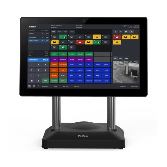
Some features of the C18 Workstation may or may not be utilized by all versions of the software. The C18 has a 18.5-inch color touchscreen with a 16:9 aspect ratio. The screen can be tilted up or down. -
Page 12: Product Warranty
An intranet infrastructure, or Cable/DSL Ethernet router, or network. The number of workstations determines the number of network switch ports required. Cables • Ethernet cable from each C18 to the network switch and/or router • If a network switch is used, an additional Ethernet cable to the router •... -
Page 13: Unpacking
C18 Workstation, P/N 182-001-01-NAA • C18 Power Supply, P/N PWR182-001-01-A • AC Power Cord, P/N CBL000-008-02-A • Cable Cover (attached to back of C18), P/N PPL182-001-01-A • C18 Hardware Installation Guide • Software Licenses The cash drawer, customer display pole, thermal printer,... -
Page 15: Installation
Installing one or two C18 workstations requires Ethernet cables to connect the C18 to the router to create an in-store LAN. The printers, customer display poles, and cash drawers use RS-232 cables to connect to the C18, and an additional Ethernet cable to connect the router to a corporate WAN/Intranet. -
Page 16: Configuring More Than Two C18 Workstations
Configuring More Than Two C18 Workstations Installing more than two C18 workstations may require a network switch and a Router. The C18 workstations use Ethernet cables to connect to the network switch. Network switches are available in various sizes and usually support four or more workstations. The network switch connects to the router using an Ethernet cable. -
Page 17: Choosing A Location
Electrical “noise” or devices that cause excessive voltage variations such as air conditioners, fans, or high frequency security systems To reduce the risk of fire, do not place the C18 near objects that produce excessive heat. Pour réduire le risque d'incendie, placer le C18 loin des objets produisant une chaleur excessive. -
Page 18: Diagnostic Panel
Diagnostic Panel The Diagnostic Panel is located on the right side of the C18 and can be accessed by lifting the cover. From left to right, this panel contains the following: • COM Port LEDs (RX/TX): These LEDs will be used for future configurations. - Page 19 PRECAUCIÓN: Existe riesgo de explosión si la batería se reemplaza por un tipo incorrecto. • Power LED: Displays Green when powered on. • System Heartbeat LED: Pulses on and off to indicate that the C18 is operating normally.
-
Page 20: C18 Rear Panel
Ethernet COM Ports Cash Drawers (2) DC Power Microphone (in) USB (6) Printer Power The rear panel of the C18 workstation has the following connections: • Printer Power • DC Power • 2 Cash Drawer Ports (Solenoid) • 1 Display Port •... -
Page 21: C18 Workstation Installation
Thermal Receipt Printer. 2. Plug the other end of the RS-232 cable into COM4 on the C18 workstation. 3. Plug the printer power cable into the printer with the flat side facing up. - Page 22 Serial RS-232 cables and Ethernet cables do not have the same pin outs and are NOT interchangeable. 6. Plug the other end of the Ethernet cable into the router (one to two C18 workstations) or to the network switch (more than two C18 workstations).
-
Page 23: Cable Cover
Cable Cover Attach or remove the Cable Cover onto the C18 using the following steps. 1. Lift up the corners of the Cable Cover to remove it. Cable Cover... - Page 24 2. Push down on the corners of the Cable Cover to attach it. Cable Cover...
-
Page 25: Keyboard
The Keyboard feature is application dependent and may not be included with your unit. Install the Keyboard Plate (P/N MET182-101-01-A) and Keyboard (PCA182-020-01-A) onto the C18 using the following steps. 1. Attach the Keyboard Plate to the C18 Base using two screws. Keyboard Plate Two Screws... - Page 26 2. Remove the Mylar covering or rubber plug from the RJ9 Port on the front of the C18 base. RJ9 Port 3. Connect the RJ9 Cable to the RJ9 Port on the Keyboard and to the RJ9 on the C18 base. Keyboard RJ9 Port 4.
-
Page 28: Biometric Reader Holder
Install the Bio Reader Plate and Bio Reader Holder either to the Keyboard or to the base of the C18 using the following steps. Keyboard Attachment Install the Bio Reader Plate and Bio Reader to the Keyboard using the following steps. - Page 29 Bio Reader Plate Screws Bio Reader Holder Keyboard Bio Reader Holder...
-
Page 30: C18 Base Attachment
C18 Base Attachment Install the Bio Reader Plate and Bio Reader Holder to the C18 base using the following steps. 1. Attach the Bio Reader Plate to the Bio Reader Holder using two screws. Bio Reader Bio Reader Plate Holder... - Page 31 2. Attach the Bio Reader Plate with Bio Reader Holder to the C18 base using two screws. C18 Base Bio Reader Holder Bio Reader Plate Screws...
-
Page 33: Service And Parts
ARTS Service Do not attempt to repair, service, or adjust the C18. Contact the Verifone Technical Support Center at 800-777-3536 with any questions related to installation or troubleshooting. Support is available 24 hours a day, seven (7) days a week. -
Page 34: Cleaning
For routine cleaning to remove dust or dirt, use a clean, damp cloth and mild soap or detergent. Use a cloth dampened with isopropyl alcohol for more stubborn stains. Parts List The table below gives the part numbers associated with the C18 workstation. Verifone P/N Description 182-001-01-NAA Unit, C18 18.5 Display... -
Page 35: Specifications
Specifications The table below gives the power requirements, dimensions, and other specifications of the C18 workstation. Specification Description Safety UL, cUL FCC Class A (USA) and CISPR22 Class A (Europe) IEC 1000 4-2 (8 KV contact, 4 KV air) Temperature Operating range: 0-40°...
Need help?
Do you have a question about the C18 and is the answer not in the manual?
Questions and answers
How do you get it working
To set up the VeriFone C18:
1. Go to the CSR Function.
2. Select Configuration Manager.
3. Press OK when the message appears.
4. Enter your username and password.
5. When prompted to set up a challenge question, press No.
6. Go to Store Operation, then PL.
7. Select TRIW PL US.
8. Find the department and price.
9. Add tax if needed.
10. Press the flu number, scan the item, and the UPC number will appear.
This completes the basic item setup process.
This answer is automatically generated