Table of Contents
Advertisement
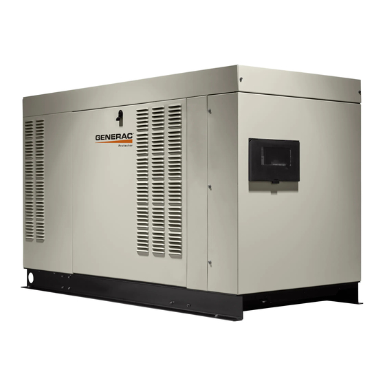
Spark-Ignited Stationary Generators
Para español , visita:
http://www.generac.com/service-support/product-support-lookup
Pour le français, visiter :
http://www.generac.com/service-support/product-support-lookup
SAVE THIS MANUAL FOR FUTURE REFERENCE
Installation Guidelines
Protector Series 48 kW
WARNING
Loss of life. This product is not intended to
be used in a critical life support application.
Failure to adhere to this warning could result
in death or serious injury.
Register your Generac product at:
WWW.GENERAC.COM
1-888-GENERAC
(888-436-3722)
(000209b)
®
Advertisement
Table of Contents

Subscribe to Our Youtube Channel
Related Manuals for Generac Power Systems Protector Series


Summary of Contents for Generac Power Systems Protector Series
- Page 1 ® Installation Guidelines Spark-Ignited Stationary Generators Protector Series 48 kW WARNING Loss of life. This product is not intended to be used in a critical life support application. Failure to adhere to this warning could result in death or serious injury.
- Page 2 Use this page to record important information about this generator. Record the information found on the unit data label on this page. For location of the unit data label, see owner’s Model: manual. The unit has a label plate affixed to the back of the control panel, inside the engine compartment.
-
Page 3: Table Of Contents
Table of Contents Section 1: Safety Rules & General Water Ingress Avoidance ......... 13 Information Proximity to Utilities .......... 13 Introduction ............1 Transportation Recommendations ....13 Read This Manual Thoroughly ........1 Site Preparation ..........13 Safety Rules ............1 Generator Foundation ..........13 How to Obtain Service ..........1 Concrete Pad ............13 General Hazards ..........2... - Page 4 Section 5: Electrical System Section 7: Installation Checklists General Information ...........29 Safety Checklist ..........43 Connecting Generator Feeder Conductors ..29 Installation Planning Checklist ......43 Connecting Control Circuit Wires ....30 Foundations and Mounting Checklist ..... 43 Removing Rear Panel and Stub-Up Cover ..30 Ventilation System Checklist ......
-
Page 5: Section 1: Safety Rules & General Information
Safety Rules & General Information Section 1: Safety Rules & General Information Introduction Safety Rules Thank you for purchasing this compact, high perfor- The manufacturer cannot anticipate every possible cir- mance, liquid-cooled, engine-driven generator. It is cumstance that might involve a hazard. The alerts in this designed to automatically supply electrical power to oper- manual, and on tags and decals affixed to the unit, are ate critical loads during a utility power failure. -
Page 6: General Hazards
Safety Rules & General Information General Hazards WARNING DANGER Moving Parts. Do not wear jewelry when starting or operating this product. Wearing Loss of life. Property damage. Installation must always jewelry while starting or operating this product comply with applicable codes, standards, laws and could result in death or serious injury. -
Page 7: Exhaust Hazards
Safety Rules & General Information Exhaust Hazards DANGER DANGER Electrocution. Verify electrical system is properly grounded before applying power. Asphyxiation. Carbon monoxide can kill Failure to do so will result in death or serious in minutes. Operate this unit outdoors only. injury. -
Page 8: Explosion Hazards
Safety Rules & General Information WARNING WARNING Fire hazard. Use only fully-charged fire Risk of Fire. Hot surfaces could ignite extinguishers rated “ABC” by the NFPA. Discharged or combustibles, resulting in fire. Fire could improperly rated fire extinguishers will not extinguish result in death or serious injury. -
Page 9: General Rules
Safety Rules & General Information General Rules DANGER DANGER Electrocution. Do not wear jewelry while working on this equipment. Doing so will Loss of life. Property damage. Installation must always result in death or serious injury. comply with applicable codes, standards, laws and (000188) regulations. -
Page 10: Standards Index
Safety Rules & General Information and local codes for minimum distances from other This list is not all-inclusive. Check with the Authority Hav- structures. ing Local Jurisdiction (AHJ) for any local codes or stan- dards which may be applicable to your jurisdiction. The •... -
Page 11: Section 2: Installation Planning
Installation Planning Section 2: Installation Planning Introduction Inspection Carefully inspect generator and all contents of cartons for any damage that may have occurred during shipment. DANGER See shipping documentation for any provisions or guid- Electrical backfeed. Use only approved switchgear to ance when damage is incurred. -
Page 12: Generator Location
Installation Planning Use a spreader bar to prevent damage to unit. Failure to • Verify installation site permits sufficient air flow for use a spreader bar will result in scratches and dam- cooling and ventilation. Consider proximity of any age to painted surfaces. walls, fences, or other noise abatement or security barriers. -
Page 13: Section 3: Site Selection And Preparation
Site Selection and Preparation Section 3: Site Selection and Preparation Site Selection Carbon Monoxide Site selection is critical for safe generator operation. It is DANGER important to discuss these factors with the installer when selecting a site for generator installation: Asphyxiation. -
Page 14: Potential Co Entry Points
Site Selection and Preparation Potential CO Entry Points Protect the Structure Figure 3-1. Generator exhaust can enter a structure Verify structure itself is correctly caulked and sealed to through large openings, such as windows and doors. prevent air from leaking in or out. Voids, cracks, or open- However, exhaust and CO can also seep into the struc- ings around windows, doors, soffits, pipes, and vents can ture through smaller, less obvious openings. -
Page 15: Fire Prevention
Site Selection and Preparation Fire Prevention The generator must be installed at a safe distance away Distance Requirements from combustible materials. Engine, alternator, and Figure 3-2. Minimum clearances must be main- exhaust system components become very hot during tained around the generator enclosure. These clear- operation. -
Page 16: Fire Codes, Standards, And Guidelines
Site Selection and Preparation Fire Codes, Standards, and Guidelines generator enclosure would not pose any ignition risk to nearby combustibles or structures, with or without fire Generator installation must comply strictly with ICC service personnel response. IFGC, NFPA 37, NFPA 54, NFPA 58, and NFPA 70 stan- dards. -
Page 17: Fresh Air For Ventilation And Cooling
Site Selection and Preparation Fresh Air for Ventilation and Cooling Site Preparation Install unit where air inlet and outlet openings will not Generator Foundation become obstructed by leaves, grass, snow, etc. If prevail- Install the generator on a concrete pad or base slab able ing winds will cause blowing or drifting, consider using a to support its weight and accessories. -
Page 18: Stub-Up Area
Site Selection and Preparation Placement on Roofs, Platforms, and Stub-Up Area Other Supporting Structures For load conduit, auxiliary power conduit (high voltage), and control wiring conduit (low voltage), see unit installa- Where required to place generator on a roof, platform, tion drawings for location and dimensions of the stub-up deck, or other supporting structure and an oil contain- area. -
Page 19: Section 4: Gaseous Fuel Systems
Gaseous Fuel Systems Section 4: Gaseous Fuel Systems Fuel Requirements and Piping strength and connections should be given special consideration when installation takes place in areas at Recommendations risk for; flooding, tornadoes, hurricanes, earthquakes, and unstable ground. DANGER NOTE: Use an approved pipe sealant or joint compound Explosion and fire. -
Page 20: Liquid Propane Gas
Gaseous Fuel Systems Liquid Propane Gas LP gas is heavier than air. The LP gas vapors are explo- liquid volume in the tank, and can be over 200 psi (1,379 sive and can be ignited by the slightest spark. LP gas is kPa). -
Page 21: Gaseous Fuel Systems
Gaseous Fuel Systems Gaseous Fuel Systems NG System Primary Regulator Outlet The utility gas provider will provide the gas meter. Con- Primary regulator outlet and generator connection point tact utility gas provider to verify they offer a gas meter must be sized correctly to provide generator with that will deliver a sufficient fuel supply. - Page 22 Gaseous Fuel Systems 009908 Manual fuel shutoff valve Primary regulator Sediment trap Flexible fuel line Figure 4-1. Typical NG System Installation Guidelines For Spark-Ignited Stationary Generators...
-
Page 23: Lp Gas System
Gaseous Fuel Systems LP Gas System Figure 4-2. LP gas uses vapors formed above liquid Fuel pressure from the primary regulator (supplied by propane in fuel supply tank (A). The maximum fuel tank installing contractor) to generator's fuel shutoff valve (B) fill capacity is 80% and a minimum of approximately 20% should be between 7–14 in water column (1.74–3.48 of fuel tank capacity is needed for fuel expansion from liq-... -
Page 24: Fuel Pressure Regulators
Gaseous Fuel Systems Fuel Pressure Regulators • Seasonal supply pressure changes to primary pressure regulator can affect correct operation of the generator. Fuel supply pressure to unit must General remain within specified operating parameters as A common cause of a generator not operating correctly is stated in the unit specification sheet. -
Page 25: Fuel Pressure Regulator Sizing
Gaseous Fuel Systems Fuel Pressure Regulator Sizing increases. It is stated as a percent, in inches of water col- umn, or in kPa, and indicates the difference between out- Fuel pressure regulators are designed to automatically let pressure at low flow rates and outlet pressure at the adjust flow to meet downstream demand at a required published maximum flow rate. -
Page 26: Pipe Sizing Considerations
Gaseous Fuel Systems Pipe Sizing Considerations General • Install supplied or recommended length of flexible fuel line between generator connection point and Contact a local fuel distributor or licensed installer when the rigid supply piping. Do not install flexible fuel sizing and installing piping for any gaseous fuel supply line underground or in contact with the ground. -
Page 27: Sizing Lp Tanks For Lp Gas Withdrawal
Gaseous Fuel Systems Table 4-2. LP Gas Pipe Sizing LP Gas 7–14 in of Water Column (1.74–3.48 kPa) Table values are maximum pipe run in ft (m) 0.75 in 1 in 1.25 in 1.5 in 2 in 2.5 in 3 in (1.9 cm) (2.5 cm) (3.2 cm) - Page 28 Gaseous Fuel Systems 4. See Table 4-3. Using both Minimum Operating Temperature and Tank Vaporization Capacity col- umns, find the BTU/hr vaporization rate of the gen- erator at 100% load corresponding to the lowest expected operating temperature. 5. See column 2, and note the Available Tank Capac- ity.
- Page 29 Gaseous Fuel Systems Table 4-3. Vaporization Rates Minimum Total Tank Available Tank Tank Vaporization Operating Length Diameter Capacity Capacity Capacity Temperature in (cm) in (cm) gal (L) gal (L) BTU/hr (MJ/hr) °F (°C) See Note 1 See Note 2 See Note 3 250 (946.4) 150 (567.8) 40 (4.4)
-
Page 30: Final Operating Test
Gaseous Fuel Systems Final Operating Test Fuel Pressure Test Port Location 1. See Figure 4-5. Using a suitable pressure gauge A correctly configured and sized fuel system provides the or water manometer, measure fuel pressure to the fuel volume and fuel pressure required for the generator generator at a test port located at the fuel solenoid set to operate correctly in all modes of operation. -
Page 31: Final Test Procedure
Gaseous Fuel Systems Gauge Adapter 1/8 Inch Diameter Probe Part No. 0K2341 009107 Figure 4-5. Fuel Pressure Test Points Final Test Procedure The following test must be performed at startup to docu- incorrectly sized, or mounted too close to the gen- ment and validate fuel system operation. - Page 32 Gaseous Fuel Systems This page intentionally left blank. Installation Guidelines For Spark-Ignited Stationary Generators...
-
Page 33: Section 5: Electrical System
Electrical System Section 5: Electrical System General Information Tighten terminal lugs to torque values noted on decal located on the inside of the door. Carefully wipe away All wiring must be correctly sized, routed, supported, and any excess corrosion inhibitor after tightening terminal connected. -
Page 34: Connecting Control Circuit Wires
Electrical System Connecting Control Circuit Wires Table 5-1. Frame Breakers Frame Generac 225 Generac 225 Generac 400 AF Generac 400 AF Control system interconnections may consist of N1, N2, Breaker AF 2 Pole AF 3 Pole 2 Pole 3 Pole and T1, and leads 23 and 194. -
Page 35: Control Wiring Connections
Electrical System in both generator and transfer switch. For general infor- (5) (6) Connect 23 in TB3 to 23 in transfer switch. Con- mation regarding wire type, temperature rating, size nect 194 in TB3 to 194 in transfer switch. These are range, and wire lug torque specifications, see Table 5-1 transfer switch control wires. -
Page 36: Two-Wire Start
Electrical System Two-Wire Start To convert control panel to two-wire start transfer switch mode of operation, see dealer for panel conversion and connection of terminals 178 and 183 in TB3. Use a 120 volt generator protected circuit from the panel board to power the battery charger circuit (dedicated 15/20 amp circuit). -
Page 37: Optional Accessory Power
Electrical System NOTE: The following table is provided for reference pur- See latest NEC, state, and local AHJ requirements poses only. See latest NEC, state, and local AHJ require- for details. ments for correct sizing. • Install power and control wires as per NEC require- ments. -
Page 38: Battery Requirements
Electrical System 1. See Figure 5-6. Install rubber protective cover (A) WARNING over positive (+) battery terminal. 2. Grasp battery strap (B) and lift battery. Environmental Hazard. Always recycle batteries at an 3. Set battery onto battery tray. official recycling center in accordance with all local laws and regulations. -
Page 39: Section 6: Control Panel Startup / Testing
Control Panel Startup / Testing Section 6: Control Panel Startup / Testing Control Panel Interface to generator output does not occur during exercise cycle unless utility power is lost. The control panel interface is located behind the door on NOTE: If installer tests generator prior to installation, the alternator end of the enclosure. -
Page 40: Before Starting, Complete The Following
Control Panel Startup / Testing Before starting, complete the following: 1. Verify generator is OFF. 2. Set generator MLCB (generator disconnect) to OFF (OPEN). 3. Turn off all breakers supplied by generator. 4. Check engine crankcase oil level and, if necessary, fill to oil dipstick FULL mark with recommended oil. - Page 41 Control Panel Startup / Testing Figure 6-2. Install Wizard Menu Map Installation Guidelines For Spark-Ignited Stationary Generators...
-
Page 42: Activate Unit
Control Panel Startup / Testing Activate Unit Display Reads: Generator Active is displayed on If the wrong language is selected, it may be the LCD screen when the unit is first changed later using the Edit menu. Up Arrow = (+) powered up. -
Page 43: Checking Manual Transfer Switch Operation
Control Panel Startup / Testing Checking Manual Transfer Switch 7. Turn off utility power supply to transfer switch when utility supply voltage is compatible with transfer Operation switch and load circuit ratings. 8. Verify both auxiliary shutdown switches are ON (I). DANGER 9. -
Page 44: Testing Auxiliary Shutdown Switch Operation
Control Panel Startup / Testing 9. Turn on circuit breaker/electrical loads to be sup- • If engine does not stop, auxiliary shutdown switch plied by generator. Loads are now powered by is not functioning correctly. Stop generator through standby generator. control panel, and inspect wiring installation. -
Page 45: Shutting Generator Down While Under Load Or During A Utility Outage
Control Panel Startup / Testing Shutting Generator Down While Under Load or During a Utility Outage DANGER Automatic start-up. Disconnect utility power and render unit inoperable before working on unit. Failure to do so will result in death or serious injury. (000191) IMPORTANT NOTE: If user finds it necessary to turn generator OFF during prolonged utility outages to... - Page 46 Control Panel Startup / Testing This page intentionally left blank. Installation Guidelines For Spark-Ignited Stationary Generators...
-
Page 47: Section 7: Installation Checklists
Installation Checklists Section 7: Installation Checklists Safety Checklist Foundations and Mounting Checklist NOTE: See Safety Rules & General Information NOTE: See Site Selection and Preparation for more more information. information. Are manuals, wiring diagrams, and other documenta- Is generator installed on a concrete pad capable of tion readily available? supporting its weight and accessories? ... -
Page 48: Ventilation System Checklist
Installation Checklists Ventilation System Checklist Is fuel regulator sized to have a fuel flow delivery rat- ing (CFH) at least 10% greater than the 100% rated NOTE: See Site Selection and Preparation for more kW fuel consumption requirement of the generator? information. -
Page 49: Electrical System Checklist
Installation Checklists Electrical System Checklist Is manual operation of transfer switch smooth and non-binding? NOTE: See Electrical System for more information. Do these parameters meet all applicable codes and Is all wiring correctly sized for load and length of run? local jurisdiction? ... - Page 50 Installation Checklists This page intentionally left blank. Installation Guidelines For Spark-Ignited Stationary Generators...
-
Page 51: Section 8: Troubleshooting/Quick Reference Guide
Troubleshooting/Quick Reference Guide Section 8: Troubleshooting/Quick Reference Guide Troubleshooting Problem Cause Correction Correct short circuit condition by replacing 7.5 Blown fuse. amp fuse in generator control panel. Loose, corroded, or faulty battery cables. Tighten, clean, or replace as necessary. Con- Faulty starter contact. -
Page 52: Quick Reference Guide
Troubleshooting/Quick Reference Guide Quick Reference Guide To clear an active alarm, press the ENTER button twice and then press AUTO. If the alarm reoccurs, contact an IASD. Active Alarm Problem Action Solution Unit running in AUTO but Check MLCB (genera- Check MLCB. - Page 53 Troubleshooting/Quick Reference Guide Active Alarm Problem Action Solution Clear alarm. Check battery option in con- Yellow LED illuminated in See screen for addi- trol menu. If it states battery is GOOD, con- LOW BATTERY YELLOW any state. tional information. tact an IASD. If it states CHECK BAT- TERY, replace battery.
- Page 54 Troubleshooting/Quick Reference Guide This page intentionally left blank. Installation Guidelines For Spark-Ignited Stationary Generators...
-
Page 55: Section 9: Accessories
Accessories Section 9: Accessories Performance enhancing accessories are available for liquid-cooled generators. Item Description Part Number Cold Weather Kit G0079920 Recommended in areas where temperatures fall below 32 °F (0 °C). Extreme Cold Weather Kit G0079900 Engine block heater. Used in conjunction with the appropriate Cold Weather Kit. - Page 56 Accessories This page intentionally left blank. Installation Guidelines For Spark-Ignited Stationary Generators...
-
Page 57: Section 10: Installation Drawings
Installation Drawings Section 10: Installation Drawings A0000293718 Rev B Page 1 of 2 SERVICE ITEM 4.5L WEIGHT DATA NOTES: OIL FILL CAP LEFT SIDE WEIGHT WEIGHT ENCLOSURE SHIPPING WEIGHT ENGINE/KW GENSET ONLY SHIPPING SKID OIL DIP STICK LEFT SIDE 1. MINIMUM RECOMMENDED CONCRETE PAD SIZE IS 6" OFFSET OF OVERALL LENGTH MATERIAL KG [LBS] KG [LBS]... -
Page 58: A0000293718 Rev B
Installation Drawings A0000293718 Rev B Page 2 of 2 13.5 X 29.5 [.53] [1.2] *NOTE: MOUNTING SLOTS STUB-UP AREA FOR HIGH AND LOW VOLTAGE CONNECTIONS, CIRCUIT BREAKER, NEUTRAL AND CUSTOMER CONNECTION OPENING. HIGH AND LOW VOLTAGE STUB-UP AREA [30.9] [6.4] STUB-UP AREA [1.7]... -
Page 59: Alternator Ac Lead Connections
Installation Drawings Alternator AC Lead Connections Alternator Power Winding Connections The electrical wires in the unit’s AC connection (lower) panel should be installed according to number of leads Three-Phase Alternators (“Y” Configuration) and voltage/phase required for the application. The volt- age and phase are described on the generator data label. -
Page 60: Three-Phase Alternators ("Delta" Configuration)
Installation Drawings Three-Phase Alternators (“Delta” Configuration) The Stationary Emergency Generator is designed to sup- ply three-phase electrical loads. Electric power is pro- duced in the alternator power windings. These windings were factory-connected to the main circuit breaker with a “Delta” configuration as shown in Figure 10-7 Fig- 10-8. -
Page 61: Alternator Wiring Diagram
Installation Drawings Alternator Wiring Diagram (1 of 4) Installation Guidelines For Spark-Ignited Stationary Generators... - Page 62 Installation Drawings Alternator Wiring Diagram (2 of 4) Installation Guidelines For Spark-Ignited Stationary Generators...
- Page 63 Installation Drawings Alternator Wiring Diagram (3 of 4) Installation Guidelines For Spark-Ignited Stationary Generators...
- Page 64 Installation Drawings Alternator Wiring Diagram (4 of 4) Installation Guidelines For Spark-Ignited Stationary Generators...
- Page 65 Installation Drawings This page intentionally left blank. Installation Guidelines For Spark-Ignited Stationary Generators...
- Page 66 Installation Drawings This page intentionally left blank. Installation Guidelines For Spark-Ignited Stationary Generators...
- Page 68 ©2019 Generac Power Systems, Inc. Generac Power Systems, Inc. All rights reserved. S45 W29290 Hwy. 59 Specifications are subject to change without notice. Waukesha, WI 53189 No reproduction allowed in any form without prior written 1-888-GENERAC (1-888-436-3722) consent from Generac Power Systems, Inc. www.generac.com...
Need help?
Do you have a question about the Protector Series and is the answer not in the manual?
Questions and answers