Advertisement
Quick Links
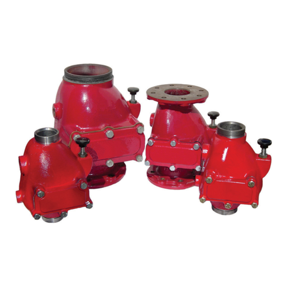
Model DPV-1 Dry Pipe Valve
External Resetting
General
Description
The TYCO Model DPV-1 Dry Pipe
Valves are differential valves used to
automatically control the flow of water
into dry pipe fire protection sprinkler
systems upon operation of one or more
automatic sprinklers. The DPV-1 also
provides for actuation of fire alarms
upon system operation. The Model
DPV-1 features are as follows:
• External reset.
• 250 psi (17,2 bar) pressure rating.
• Unique offset single clapper design
enabling a simple compact valve to
minimize installation labor.
• Ductile iron construction to ensure
a lightweight valve to minimize ship-
ping cost.
• A variety of inlet and outlet
connections.
• Compact, Pre-Trimmed, and Semi-
Assembled, easy to operate valve
trim.
• Simple reset procedure through the
elimination of priming water.
Dry pipe sprinkler systems are used
in unheated warehouses, parking
garages,
store
windows,
spaces, loading docks, and other
areas exposed to freezing tempera-
tures, where water filled pipe cannot
be utilized. When set for service, the
dry pipe sprinkler system is pressur-
ized with air (or nitrogen). The loss of
pressure through an operated auto-
matic sprinkler in response to heat
from a fire permits the DPV-1 Dry
Pipe Valve to open and allow a flow of
water into the sprinkler system piping.
Table B establishes the minimum
required system air pressure that
includes a safety factor to help prevent
false operations that might occur due
to water supply fluctuations.
IMPORTANT
Refer to Technical Data Sheet
TFP2300 for warnings pertaining to
regulatory and health information.
Page 1 of 20
End Connection
Flange x Flange
Flange x Groove
Groove x Groove
• = Available
N/A = Not Available
NOTICE
attic
The Model DPV-1 Dry Pipe Valves
described herein must be installed
and maintained in compliance with
this document, as well as with the
applicable standards of the National
Fire Protection Association, in addition
to the standards of any other authori-
ties having jurisdiction. Failure to do so
may impair the performance of these
devices.
The owner is responsible for main-
taining their fire protection system
and devices in proper operating con-
dition. Contact the installing contrac-
tor or product manufacturer with any
questions.
Technical Data
Approvals
UL and C-UL Listed
FM Approved
NYC Approved
MAY 2020
Worldwide
Contacts
Available Sizes and End Connections
Nominal Valve Size
2-1/2 in.
3 in.
(DN65)
(DN80)
N/A
N/A
N/A
N/A
•
•
Dry Pipe Valve
The TYCO Model DPV-1 Dry Pipe
Valves shall be installed in the verti-
cal orientation only (supply at bottom
flowing upward) and are rated for use at
a maximum service pressure of 250 psi
(17,2 bar). Valve and trim dimensions
are shown in Figure 6.
Flanged connections are available and
drilled per ANSI, ISO, AS, and JIS spec-
ifications, see Table A. The grooved
outlet connections, as applicable, are
cut in accordance with standard groove
specifications for steel pipe. They are
suitable for use with grooved end pipe
couplings that are listed or approved
for fire protection system service.
Available combinations of inlet and
outlet connections are described in
the Ordering Procedure section and in
the Available End Connection and Sizes
table on page 1.
Trim port connections of valves having
flanges drilled to ANSI, AS, or JIS spec-
www.tyco-fire.com
4 in.
6 in.
(DN100)
(DN150)
•
•
•
•
•
•
TFP1020
Advertisement

Related Manuals for Johnson Controls TYCO DPV-1


Summary of Contents for Johnson Controls TYCO DPV-1
- Page 1 Worldwide www.tyco-fire.com Contacts Model DPV-1 Dry Pipe Valve External Resetting General Description The TYCO Model DPV-1 Dry Pipe Valves are differential valves used to automatically control the flow of water into dry pipe fire protection sprinkler systems upon operation of one or more automatic sprinklers.
- Page 2 TFP1020 Page 2 of 20 NO. DESCRIPTION QTY. REF. Valve Body ..Air and Water Seat ... . Handhole Cover . . . Handhole Cover Gasket .
- Page 3 TF1020 Page 3 of 20 NO. DESCRIPTION QTY. REP. PART NO. DESCRIPTION QTY. REP. PART NO. DESCRIPTION QTY. REP. PART Valve Body ..Socket Head Cap Hex Head Cap Screw Air and Water Screw 5/8-11 UNC x 1"...
- Page 4 TFP1020 Page 4 of 20 Flange Drilling Specification Dim. A Nominal Dimensions in Inches and (mm) Bolt Circle Nominal ANSI B16.1 ISO 7005-2 JIS B 2210 AS 2129 Valve Diameter (Class 125) (PN16) (10K) (Table E) Size Dim. B Dim. Dim.
-
Page 5: Operation
TF1020 Page 5 of 20 FLOW RATE IN LITRES PER MINUTE (LPM) Maximum System Air (1 GPM = 3.785 LPM) Water Supply Pressure Pressure Range 500 700 1000 2000 3000 5000 10000 0,60 0,50 15 - 23 0,40 20 - 28 0,30 25 - 33 30 - 38... -
Page 6: Installation
TFP1020 Page 6 of 20 Installation • Care must be taken to make sure • It is best practice to install an appro- that components such check valves, priately rated and listed relief valve strainers, and globe valves are upstream of the Model DPV-1 Dry General Instructions installed with the flow arrows in the Pipe Valve, between the inlet of the... - Page 7 TF1020 Page 7 of 20 Valve Setting Step 5. As necessary, replace all sprin- to the Care and Maintenance section klers that have operated. Replacement under Automatic Drain Valve Inspection Procedure sprinklers must be of the same type to determine/correct the cause of the and temperature rating as those which leakage problem.
- Page 8 TFP1020 Page 8 of 20 AIR PRESSURE WATERFLOW TO SYSTEM TO SYSTEM CLAPPER CLAPPER ASSEMBLY ASSEMBLY 1" NPT IN SET FULLY OPEN AIR SUPPLY POSITION PORT CLAPPER LATCH PIVOTS TO ALLOW 1/2" NPT CLAPPER ASSEMBLY WATER TO FULLY OPEN SUPPLY PRESSURE 3/4"...
- Page 9 TF1020 Page 9 of 20 AIR PRESSURE WATERFLOW TO SYSTEM TO SYSTEM CLAPPER ASSEMBLY FULLY OPEN 1" NPT CLAPPER LATCH AIR SUPPLY PIVOTS TO ALLOW PORT CLAPPER ASSEMBLY TO FULLY OPEN 3/4" NPT ALARM PORT OPEN TO CLAPPER ATMOSPHERE ASSEMBLY IN SET POSITION 1/2"...
- Page 10 TFP1020 Page 10 of 20 NOTES: 1. SEE FIGURE 3 PART 3 FOR TRIM ARRANGEMENT WITH BILL OF MATERIALS LOW AIR AND COMPONENT PART NUMBERS. PRESSURE ALARM TRIM SHOWN FULLY ASSEMBLED; COMPONENTS SUCH AS GAUGES AND SYSTEM SWITCH SWITCHES MAY REQUIRE ASSEMBLY IN TRIM AT INSTALLATION. AIR SUPPLY CONTROL VALVE 1 INCH NPT...
- Page 11 TF1020 Page 11 of 20 DESCRIPTION DESCRIPTION DESCRIPTION 250 psi/ 1750 kPa 3/32" Vent 1" x 1" x 1/2" Air Pressure Fitting ... 92-032-1-002 Reducing Tee ..Gauge .
- Page 12 TFP1020 Page 12 of 20 1. SEE FIGURE 4 PART 3 FOR TRIM ARRANGEMENT WITH BILL OF MATERIALS LOW AIR AND COMPONENT PART NUMBERS. PRESSURE ALARM TRIM SHOWN FULLY ASSEMBLED; COMPONENTS SUCH AS GAUGES AND SYSTEM SWITCH SWITCHES MAY REQUIRE ASSEMBLY IN TRIM AT INSTALLATION. AIR SUPPLY CONTROL VALVE 4 INCH (DN100)
- Page 13 TF1020 Page 13 of 20 NOTES: 1. SEE FIGURE 2 FOR VALVE PORT IDENTIFICATION. ROUTE 1/4" TUBING, ITEM 16, TO DRIP FUNNEL, ITEM 14. (GREEN SLOPE 3/4" ANGLE VALVE, TINT) ITEM 9, DOWN TOWARD BACK OF VALVE TO SLOPE FACILITATE SUFFICIENT DOWN LOW BODY DRAINAGE.
- Page 14 TFP1020 Page 14 of 20 NOTES: 1. SEE FIGURE 5 PART 3 FOR TRIM ARRANGEMENT WITH BILL OF MATERIALS LOW AIR AND COMPONENT PART NUMBERS. PRESSURE ALARM TRIM SHOWN FULLY ASSEMBLED; COMPONENTS SUCH AS GAUGES AND SYSTEM SWITCH SWITCHES MAY REQUIRE ASSEMBLY IN TRIM AT INSTALLATION. AIR SUPPLY CONTROL VALVE SYSTEM...
- Page 15 TF1020 Page 15 of 20 BACK OF NOTES: SEE FIGURE 2 FOR VALVE ALL FITTINGS AND NIPPLES VALVE PORT IDENTIFICATION. ARE GALVANIZED. ROUTE 1/4" TUBING, ITEM 16, CH: COMMON HARDWARE TO DRIP FUNNEL, ITEM 14. ITEMS 45−48 INCLUDED ONLY IN PRE-TRIMMED SLOPE 3/4"...
- Page 16 TFP1020 Page 16 of 20 7-1/8" 8-3/8" 14-7/8" 9-1/4" (180 mm) (213 mm) (380 mm) (235 mm) 2-1/2 & 3 INCH (DN65 & DN80) VALVE 20-7/16" (520 mm) 16-1/8" (409,6 mm) 2-1/2 or 3 INCH VALVES 12" 9-5/8" 12" 14" (300 mm) (245 mm) (300 mm)
- Page 17 TF1020 Page 17 of 20 6-3/4" 8" 14-7/8" 9-1/4" (170 mm) (200 mm) (380 mm) (235 mm) 2-1/2 & 3 INCH 16-9/16" (DN65 & DN80) (420,7 mm) VALVE 12-1/4" (311,2 mm) 2-1/2 or 3 INCH VALVES 6" (150 mm) 12" 6"...
-
Page 18: Care And Maintenance
TFP1020 Page 18 of 20 4" 6" MODEL DPV-1 VALVE MODEL DPV-1 VALVE WITH TRIM WITH TRIM INSTALL DRAIN KIT SUB-ASSEMBLIES IN ALPHABETICAL ORDER, REUSE ITEM C DRIP FUNNEL INCLUDED WITH STANDARD VALVE TRIM REMOVE AND DISCARD DRIP FUNNEL BRACKET REMOVE AND DISCARD 3/4"... - Page 19 TF1020 Page 19 of 20 Automatic Drain Valve Inspection Step 3. Disassemble the Clapper The Automatic Drain Valve should be Facing Retainer from the Clapper Nominal Torque Valve Sizes inspected monthly (per NFPA 25) by so that the Clapper Facing can be lb-ft depressing the plunger and check- removed and inspected.
- Page 20 1400 Pennbrook Parkway, Lansdale, PA 19446 | Telephone +1-215-362-0700 © 2020 Johnson Controls. All rights reserved. All specifications and other information shown were current as of document revision date and are subject to change without notice. NATIONAL FIRE PROTECTION ASSOCIATION and NFPA are registered trademarks of National Fire Protection Association;...
Need help?
Do you have a question about the TYCO DPV-1 and is the answer not in the manual?
Questions and answers