Advertisement
Quick Links
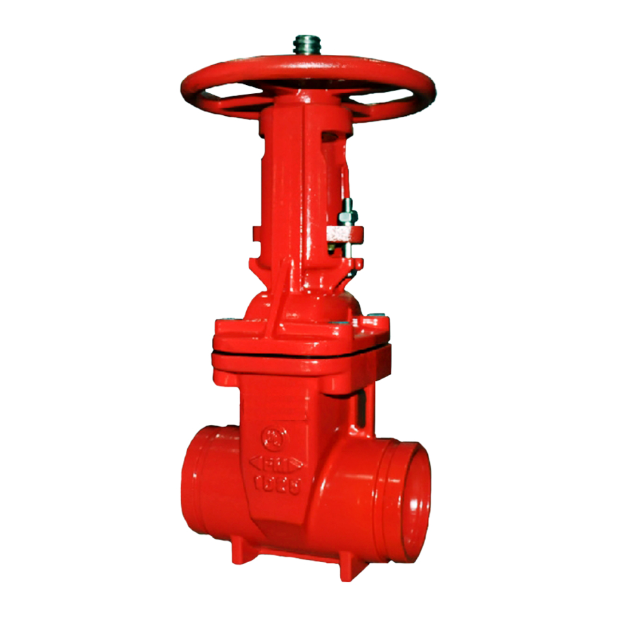
Resilient-Seated Gate Valves
with Vertical or Cross Wall Post Indicator
General
Description
TYCO Resilient-Seated Gate Valves
with Vertical and Cross Wall Indicators
are used in fire protection systems for
on/off operation. End connection con-
figurations including Flange by Flange,
Flange by Groove, and Groove by
Groove are available.
The ductile iron body weighs approx-
imately 50% less than conventional
cast iron valves, which allows easier
handling on site and reduced shipping
costs.
The fully encapsulated EPDM ductile
iron wedge ensures drop-tight sealing.
Valve components are either inher-
ently corrosion-resistant or protected
with fusion-bonded epoxy resin coating
for a long, reliable service life and
enhanced UV protection in exposed
installations.
This valve is one of the lightest, most
durable gate valves on the market
today. Its design features and material
selection criteria fulfill the need for a
reliable, long life and easy to operate
gate valve.
These valves are available with either
Vertical Indicators for underground
water supplies or Cross Wall Indicators
for interior water systems. Both indica-
tors provide external visual indication
of the open or shut valve condition as
well as a locking mechanism to secure
a particular wedge position.
IMPORTANT
Refer to Technical Data Sheet
TFP2300 for warnings pertaining to
regulatory and health information.
Page 1 of 16
NOTICE
Never remove any piping component
nor correct or modify any piping defi-
ciencies without first de-pressurizing
and draining the system. Failure to do
so may result in serious personal injury,
property damage, and/or impaired
device performance.
It is the designer's responsibility
to select products suitable for the
intended service and to ensure that
pressure ratings and performance data
are not exceeded. Material and gasket
selection should be verified for com-
patibility with the specific application.
Always read and understand the instal-
lation instructions.
TYCO Gate Valves described herein
must be installed and maintained in
compliance with this document, in
addition to the standards of any other
authorities having jurisdiction. Failure
to do so may result in serious personal
injury or impair the performance of
these devices.
The owner is responsible for main-
taining their mechanical system and
devices in proper operating condition.
The installing contractor or device man-
ufacturer should be contacted with any
questions.
MAY 2021
Worldwide
www.tyco-fire.com
Contacts
TFP1546
Advertisement

Related Manuals for Johnson Controls Tyco TJPX0500003


Summary of Contents for Johnson Controls Tyco TJPX0500003
- Page 1 Worldwide www.tyco-fire.com Contacts Resilient-Seated Gate Valves with Vertical or Cross Wall Post Indicator General Description TYCO Resilient-Seated Gate Valves with Vertical and Cross Wall Indicators are used in fire protection systems for on/off operation. End connection con- figurations including Flange by Flange, Flange by Groove, and Groove by Groove are available.
- Page 2 TFP1546 Page 2 of 16 No. Description Qty. Material 1 Body..1 ASTM A536 65-45-12 2 Wedge ..1 EPDM 3 Stem..1 AISI SS240 4 Bonnet .
- Page 3 TFP1546 Page 3 of 16 Nominal Dimen- Nominal Nominal sions Approx. Approx. Approx. Valve Size Pipe Size in. (mm) Tapping Weight Weight Weight Boss Size F x F F x G G x G ANSI in. ANSI O.D. (kg) (kg) (kg) (mm) 2.375...
- Page 4 TFP1546 Page 4 of 16 No. Description Qty. Material 1 Locking Wrench..1 ASTM A126B 2 Operating Nut ..1 SUS304 3 Hex Cap Screw ..2 ASTM A105 4 Hex Nut .
- Page 5 TFP1546 Page 5 of 16 SUPERVISORY SWITCH (NOT INCLUDED) INDICATOR WINDOW Nominal Valve CL to WRENCH LOCK Valve Finished Grade (NOT INCLUDED) Post Size Type (mm) (mm) (mm) WRENCH Minimum Maximum 29.25 63.50 UPPER POST DN50 (744) (1614) 31.13 65.38 DN100 (791) (1661)
-
Page 6: Installation
TFP1546 Page 6 of 16 Installation Vertical Indicator Post, 4 in. to 12 in. (DN100 to DN300) Valves Step 1 Step 2 Step 3 Step 1. Rotate gate valve top cap Step 2. Remove indicator wrench and Step 3. Remove cap assembly from clockwise to fully open gate valve. - Page 7 TFP1546 Page 7 of 16 Step 10 Step 11 Step 12 LINE Step 10. Remove connection tube from Step 11. Temporarily detach indica- Step 12. Secure indicator to gate valve body and cut at cut line. tor from gate valve and raise to gain with bolts and nuts.
- Page 8 TFP1546 Page 8 of 16 Installation Vertical Indicator Post, 14 in. to 24 in. (DN350 to DN600) Valves Step 1 Step 2 Step 3 Step 1. Rotate gate valve top cap Step 2. Remove top cap from gate Step 3. Remove indicator wrench and clockwise to fully open gate valve.
- Page 9 TFP1546 Page 9 of 16 Step 10 Step 11 Step 12 1-1/2" (40 mm) LINE LINE Step 10. Mark cut line on connection Step 11. Remove connection tube from Step 12. Temporarily detach indica- tube 1 1/2 in. (40 mm) above top flange body and cut at cut line.
- Page 10 TFP1546 Page 10 of 16 No. Description Qty. Material No. Description Qty. Material No. Description Qty. Material 1 Lifting Eye 10 Target ..4 ASTM B108 18 Connection Bolt..1 ASTM A307B Tube .
- Page 11 TFP1546 Page 11 of 16 Nominal Nominal Valve CL to Valve CL to Valve Valve Exterior Wall Exterior Wall Size Size (mm) (mm) Minimum Maximum Minimum Maximum 10.75 98.36 20.19 107.81 DN50 (273) (2500) DN200 (513) (2738) 12.75 100.36 24.25 111.81 DN100 (325)
- Page 12 TFP1546 Page 12 of 16 Installation Wall Indicator Post, 2 in. to 12 in. (DN100 to DN300) Valves Step 1 Step 2 Step 3 Step 1. Rotate gate valve top cap Step 2. Remove indicator cap bolts Step 3. Remove cap assembly from clockwise to fully open gate valve.
- Page 13 TFP1546 Page 13 of 16 Step 10 Step 11 Step 12 Step 10. Insert connection tube Step 11. Insert cap assembly into body Step 12. Secure cap to body with bolts through body and standpipe and cavity, aligning carrier yoke keyway and nuts.
-
Page 14: Technical Data
TFP1546 Page 14 of 16 FLOW RATE IN LITRES PER MINUTE (LPM) (1 GPM = 3,785 LPM) 1000 2000 3000 4000 6000 10000 20000 30000 0.30 0,020 0.20 0,010 0,009 0,008 0,007 0.10 0.09 0,006 0.08 0,005 0.07 0.06 0,004 0.05 800 1000 2000... - Page 15 TFP1546 Page 15 of 16 Nominal Nominal Valve Pipe Part Number Size Size Flange x Flange x Flange x Flange x Flange x ANSI O.D. Flange Flange Groove Groove Flange Groove x Inches Inches ANSI ISO 7005-2 ANSI ISO 7005-2 AS 2129 Groove (mm)
- Page 16 1400 Pennbrook Parkway, Lansdale, PA 19446 | Telephone +1-215-362-0700 © 2021 Johnson Controls. All rights reserved. All specifications and other information shown were current as of document revision date and are subject to change without notice. NATIONAL FIRE PROTECTION ASSOCIATION and NFPA are registered trademarks of National Fire Protection Association;...
Need help?
Do you have a question about the Tyco TJPX0500003 and is the answer not in the manual?
Questions and answers