
Related Manuals for Kirisun DP580


Summary of Contents for Kirisun DP580
- Page 1 Professional wireless communication system solution supplier DP580 SERVICE MANUAL ShenZhen Kirisun Communications Co.,Ltd. V190312...
-
Page 2: Table Of Contents
DP580 Service Manual Contents Overview ..................................1 1.1. Range of Application ..............................1 1.2. Safety Precaution ................................1 1.3. Maintenance Service ..............................1 2 External View and Keys ............................... 2 2.1. External View ................................. 2 2.2. Programmable Keys ............................... 3 2.3. - Page 3 Figure 3 Schematic Diagrams of Main Board DP580-05......................109 Figure 4 Top-Layer Layout Drawing of Main Board DP580-01....................121 Figure 5 Bottom-Layer Layout Drawing of Main Board DP580-01 ..................122 Figure 6 Top-Layer Layout Drawing of Main Board DP580-02 ....................123 Figure 7 Bottom-Layer Layout Drawing of Main Board DP580-02 ..................
-
Page 4: Overview
This manual is intended for the maintenance of DP580 frequency-modulated handheld two-way radio, and can be used only by the engineers and professional technicians trained by Kirisun. The parameters in this manual are subject to change because of technology improvement. For the latest information, please contact Kirisun or your local dealer. -
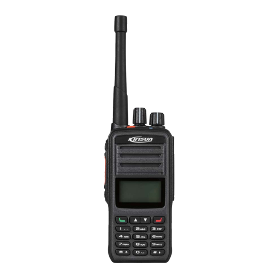
Page 5: External View And Keys
DP580 Service Manual No provision of a valid warranty card or an original invoice Malfunction due to unpermitted disassembly, repair or modification Damage of the product due to wear, mechanical damage, burn or inlet of water ... -
Page 6: Programmable Keys
DP580 Service Manual Part Name Part Name Output voice. Channel Knob Rotate it to select one from the channels 1 to Belt Clip Power/Volume Knob Turn it clockwise until a click is heard to power on the radio. Turn it counterclockwise Battery Latch until a click is heard to power off the radio. -
Page 7: Led Indicator
DP580 Service Manual NO. Programming Function Function Description Call 1 to Call 6 Press the key to call CALL 1 to CALL 6. Encryption Digital encryption GPS switch Enable/ disable GPS function. 2.3.LED Indicator LED Indication Radio State Red light on Transmitting signals. -
Page 8: Receiving A Call
DP580 Service Manual 3.5.Receiving a Call When the radio receives RF signals on the selected channel and the squelch level is reached, the green LED glows to indicate that carrier is received. When the selected channel is digital channel and when it received individual call, group call or all call, the radio will output the voice from the channel. -
Page 9: Circuit Description
DP580 Service Manual 4.Circuit Description 4.1.Main Board... -
Page 10: Tx Circuit
DP580 Service Manual 4.2.Tx Circuit The Tx channel circuit includes an RF power amplification circuit, a low pass filter circuit and an automatic power control circuit. RF Power Amplification Circuit Transmitting signals TX LO are buffered and amplified by the Q8 and Q9, enter the pre-drive amplifier (Q10) for amplification, and output strong enough drive power signals, and then power is amplified by the end-level amplifier (Q11). -
Page 11: Rx Circuit
DP580 Service Manual 4.3.Rx Circuit The receiving circuit mainly consists of an RF circuit, an MF circuit and MF signal processing, which are described as below. RF Circuit Signals from the antenna are filtered through a low-pass filter circuit, transmitted by the RX/TX switch (D14. -
Page 12: Audio Amplification Circuit
DP580 Service Manual 4.4.Audio Amplification Circuit The master chip LT1901 processes signals to get differential audio signals, which are amplified by an audio power amplifier and output via the speaker or the headset. 4.5.Frequency Synthesis Circuit The frequency synthesis circuit consists of the phase-locked loop (PLL) chip LMX2571, a loop filter (LPF), a voltage-controlled oscillator (VCO) and a feedback network. -
Page 13: Other Circuits
DP580 Service Manual and the TX VCO for modulation. 4.6.Other Circuits If required, such functions as Bluetooth, GPS and Man Down can be provided by adding corresponding circuits. 4.7.Power Supply The radio is powered by a 7.4V lithium battery. The RF amplifier and the audio amplifier are powered by the B+ connected to a fuse. - Page 14 DP580 Service Manual Pin NO. Port NO. Net Label Description level) Enable transmitting power amplification GPIO_D50 TXENABLE (valid at high level) AB16 Enable GPS receiving (valid at high GPIO_D104 GPSENABLE level) RXD1 RXD1 Output GPS module data TXD1 TXD1 Input GPS module data...
- Page 15 DP580 Service Manual Pin NO. Port NO. Net Label Description Switch to internal/external microphone GPIO_D109 MICSELECT (external at high level) Switch to internal/external speaker AA15 GPIO_D30/D93 PASELECT (external at high level) AC16 GPIO_D110 MUTE Speaker mute (mute at low level)
-
Page 16: Feature Description And Parameter Setting
DP580 Service Manual Pin NO. Port NO. Net Label Description GPIO_D13 KC_R3 Key pad GPIO_D100 KEYPAD_BL Backlight of key pad USB_DM USB_DM USB port USB_DP USB_DP USB port HPL_OUT MODE1 Output of crystal modulation HPR_OUT MODE2 Output of VCO modulation... -
Page 17: Scan
DP580 Service Manual 5.2.Scan Enabling Scan Press the Scan programmable key to enable Scan and listen to activities on other channels. Press Scan key again to exit Scan. Scan List Each channel can be related to one “Scan List” though dealer programming. The radio can only start Scan on channels related with “Scan List”. -
Page 18: Tot (Time-Out-Timer)
DP580 Service Manual interference there will be and the harder to receive weak signals. Alert Tone You can enable or disable various alert tones via the PC Tool. Microphone Gain Microphone gain is the value based on which an audio level is amplified. You can adjust volume by setting a microphone gain. -
Page 19: Settings
The radio has been set before delivery. However, to meet customers’ requirements, it may be necessary to set such digital functions as operating frequencies, channels, DT/DQT and automatic scan. This can be achieved by the programming software CPSM V3.xx developed by Kirisun. It is user-friendly and easy to operate, and supports Chinese and English. -
Page 20: Upgrade
DP580 Service Manual Step 4.After successful connection, [USB OK] will be displayed in the title bar, and a USB connection symbol will be displayed in the upper right corner of the screen of the radio. Step 5.In the software interface, select Program Read Data. In the prompted dialog box, click Read. The radio parameters will be read. -
Page 21: Installing And Uninstalling The Antenna
DP580 Service Manual Uninstalling the Battery Step 1. Power off the radio. Step 2. Slide the latch in the indicated direction, and the battery will go up. (Figures ① and ②) Step 3. Slice the battery in the indicated direction to take it down. (Figure ③) If the belt clip is installed, please first press the upper part of it so that it goes up. -
Page 22: Using An Earphone
DP580 Service Manual 6.4.Using an Earphone To connect an earphone, remove the earphone cover at the upper part of the right side of the radio and keep it well for further use, plug the earphone connector into the jack. 6.5.Detaching Housing from the Base Step 1. -
Page 23: Explosion Diagram
DP580 Service Manual After disassembly is finished, you can repair and modulate the radio. 6.7.Explosion Diagram Material Code Material Name Specification Nameplate for radio Aluminum-alloy, wire drawing, 7PLJ-4230-E01A DP585 silver text, lead free 7MHP-4245-02A-W8 Front shell cover PC1414, gray, etched... - Page 24 DP580 Service Manual Material Code Material Name Specification Side key cap (up) for radio PC1414, black, etched 7MHP-4207-05A-W0 DP586 (cover die 1) Plastic PTT key for radio PC1414, co-molding dual-color, 7MHP-4207-01A-W0 DP586 pantone 172c+, black Silicon PTT key for radio...
- Page 25 DP580 Service Manual Material Code Material Name Specification R M2*4 cross recessed Hardened iron, Φ2mm*4mm, 7SMF-020040M-SZY mushroom-head machine nickel plated screw Silicon rubber, outer diameter 8 7MHR-4072-05A-W0 O-shaped ring mm, wire diameter 1.5 mm Main board M2.0*3.7 cross recessed 7SMF-020037M-SZC...
-
Page 26: Debugging
T=0.2mm, 2-layer PC1414, black, etched, screen 7MHP-4245-01A-W0 Front housing print Transparent PC, screen print 7PLJ-4245-E01A Model sticker “DP580”, grayish white text Dual-sided adhesive for 7MHJ-4245-01A-W 3M9448 key PCB SMD nesting of key PCB 6SS2-4245-HK1A of radio DP580 Metal dome array of SUS301, Φ5mm, four-point... -
Page 27: Modulation In Pc Test Mode
DP580 Service Manual 7.1.2.Modulation in PC Test Mode Tx Frequency Run the debugging software on the PC, set the all-purpose tester to adjustment mode, select [Frequency Stability], and adjust to a maximum transmitting frequency of 100Hz above the rated frequency and a minimum one of 100Hz below the rated frequency. -
Page 28: General Specification
DP580 Service Manual Tx Part 1. Output power: High (3.5W---4.5W), low (0.7W---1.5W) 2. Transmitting Current: High-power (<= 1.7A), low-power (<=1.2A) 8.General Specification Model DP580 Frequency Range 136~174 MHz, 350~400 MHz, 400~470 MHz Channel Capacity 16 partitions*16 channels Channel Spacing 25 kHz/20KHz/12.5kHz Operating Voltage 7.4V, cathode grounded... -
Page 29: Troubleshooting
DP580 Service Manual Digital multimeter Regulated DC power supply Dummy load 16Ω 10.Troubleshooting Failure Description Troubleshooting Startup fails A. Check the battery. If it is low, charge or replace it. B. The Power key does not work well. Replace the key. -
Page 30: Appendix 1 Abbreviations
DP580 Service Manual Appendix 1 Abbreviations Amplify, amplifier Antenna Automatic power control Band-pass filter CTCSS Continuous tone control squelch system Digital code squelch DEMOD Demodulation E2PROM Electrically Erasable Programmable Read-Only Memory High-pass filter Instantaneous deviation control Intermediate frequency Light-emitting diode... -
Page 31: Appendix 2 Material List (Electronic Part)
DP580 Service Manual Appendix 2 Material List (Electronic Part) Table 1 Material List of Main Board DP580-01 Part NO. Part Name Specification QTY Position C1,C6,C10,C29,C81,C82,C83,C84,C123,C125,C127,C140,C 2CC1-10-C0G500-15 R multi-layer chip 1005, 150P±5%, 50V, C0G 142,C153,C172,C182,C189,C196,C198,C219,C221,C226,C2 capacitor 50,C251,C252,C255,C61 C2,C7,C11,C20,C25,C26,C30,C105,C108,C157,C383,C193, C235,C239,C245,C280,C282,C295,C297,C304,C169,C330,C 337,C339,C551,C49,C369,C372,C379,C389,C390,C396,C40 2CC1-10-X7R500-10... - Page 32 DP580 Service Manual Part NO. Part Name Specification QTY Position C21,C183,C188,C195,C197,C218,C220,C224,C225,C232,C2 2CC1-10-X7R500-10 R multi-layer chip 1005,10nF±10%, 50V, X7R 33,C238,C253,C293,C55,C326,C327,C328,C329,C331,C356 capacitor ,C357 C24,C48,C73,C91,C92,C95,C96,C103,C104,C110,C111,C12 6,C128,C139,C141,C143,C152,C155,C156,C158,C159,C161 ,C234,C244,C249,C260,C264,C281,C283,C294,C296,C298, C475,C333,C334,C340,C346,C349,C359,C437,C549,C550,C 2CC1-10-X7R160-10 R multi-layer chip 1005, 100nF±10%, 16V, X7R 67,C68,C423,C424,C425,C426,C427,C428,C440,C441,C455 capacitor ,C456,C544,C545,C433,C435,C442,C449,C450,C453,C454, C457,C458,C461,C386,C387,C436,C451,C478,C479,C485,C 491,C492,C498,C499,C505,C506,C507,C42,C459,C460,C46 6,C518,C519 C32,C35,C39,C307,C393,C398,C403,C404,C448,C527,C530 2012, 10uF±10%, 16V, TAIYO,...
- Page 33 DP580 Service Manual Part NO. Part Name Specification QTY Position FB38,FB39,FB40,FB17,FB20,FB41,FB47,FB48,FB5,FB6,FB7 1005,1KΩ [Made in China] 5FE1-CB100505-102 R SMD EMI filter ,FB8,FB9,FB10,R38,FB14,FB15,FB18,FB46,R222,R246,R25 4,R255,R256,R271,R272,R273 SMD switch power supply MP2359, 6PIN, 1.2A 24V, 1IS1-MP2359 1.4MHz, TSOT-23-6 1IS1-XC6209B552MR SMD voltage regulator IC 5.5V, SOT-23-5 encapsulation...
- Page 34 DP580 Service Manual Part NO. Part Name Specification QTY Position R146,R155,R262,R264,R57,R58,R59,R94,R106,R107,R115, 2RS1-10-104J R chip resistor 1005, 100K±5% R116,R307,R29,R228 1005, 470Ω±5% 2RS1-10-471J R chip resistor R154,R261,R263,R231,R306,R259,R260,R301 2CC1-10-C0G500-2R R multi-layer chip 1005, 2.5P±0.1P, 50V, C0G C69,C70,C71,C477,C173 capacitor 2CC1-10-C0G500-2R Multi-layer chip capacitor 1005, 2P±0.1P, 50V, C0G...
- Page 35 DP580 Service Manual Part NO. Part Name Specification QTY Position 1608, 10nH±5% 2LL1-16-10NJA Multi-layer chip inductor (SDCL1608C10NJTDF), SunLord 2LG1-VLS3012ET-10 VLS3012ET-100M, 10uH+20%, SMD power inductor 3*3*1.2MM 1608, 8.2nH±0.5nH 2LL1-16-8N2DA Multi-layer chip inductor (SDCL1608C8N2JTDF), SunLord 2RS1-10-473J R chip resistor 1005, 47K±5% R12,R18,R52,R119,R123,R226,R227,R153,R302...
- Page 36 DP580 Service Manual Part NO. Part Name Specification QTY Position 3216, 0.1μF±20%, 35V, TS 2CT1-TS32-350-R10 R SMD Tantalum capacitor C114 series (Encapsulation A) 2CC1-32-X7R500-10 R multi-layer chip 3216, 1000P±10%, 50V, X7R C115 capacitor 2CC1-10-C0G500-12 R multi-layer chip 1005, 12P±5%, 50V, C0G...
- Page 37 DP580 Service Manual Part NO. Part Name Specification QTY Position 2CC1-10-X7R500-47 R multi-layer chip 1005, 470P±10%, 50V, X7R C150,C151,C181,C229,C230,C231,C385 capacitor 2012, 4.7μF±20%, 10V, TP 2CT1-TP20-100-4R7 R SMD Tantalum capacitor C402 series (Encapsulation P) 1DV1-1SV325 R SMD varactor 1SV325 (V8) D4,D5,D6,D7,D8,D9,D10,D11...
- Page 38 DP580 Service Manual Part NO. Part Name Specification QTY Position 1608, 18nH±2% 2LL1-16-18NG Multi-layer chip inductor (ELJRE18NGFA) 1608, 180nH±5%, ceramic core 2LW1-16UC-181J SMD wire wound inductor L27,L31,L47 (C1608CB-R18J) BFU550A, NXP, SOT23 1TT1-BFU550A RF triode Q3,Q104,Q9,Q12 encapsulation 1TT1-2SC4617-R R SMD triode...
- Page 39 DP580 Service Manual Part NO. Part Name Specification QTY Position oscillator ±37ppm, -40℃~85℃, 3225 encapsulation 2CC1-16-C0G500-47 R multi-layer chip 1608, 47P±5%, 50V, C0G capacitor 2CC1-16-C0G500-33 Multi-layer chip capacitor 1608, 33P±5%, 50V, C0G 2CC1-16-C0G500-68 R multi-layer chip 1608, 68P±5%, 50V, C0G...
- Page 40 DP580 Service Manual Part NO. Part Name Specification QTY Position 2CC1-16-C0G500-20 R multi-layer chip 1608, 20P±5%, 50V, C0G C213 capacitor 2CC1-16-C0G500-11 R multi-layer chip 1608,11P±5%,50V,C0G C214 capacitor 2CC1-16-C0G500-22 R multi-layer chip 1608, 22P±5%, 50V, C0G C215 capacitor 2CC1-10-C0G500-27 Multi-layer chip capacitor 1005, 270P±5%, 50V, C0G...
- Page 41 DP580 Service Manual Part NO. Part Name Specification QTY Position 1608, 56Ω±5% 123 2RS1-16-560J R chip resistor (SC) wire diameter φ 0.40, inner 2LH1-R401R5-R08-0 diameter φ 1.5, 8-wind, forward R SMD air core inductor winding, long pin Wire diameter φ 0.30, inner diameter φ...
- Page 42 DP580 Service Manual Part NO. Part Name Specification QTY Position Wire diameter φ 0.30, inner diameter φ 1.2, 5-wind, reverse 134 2LH1-R301R2-L05-05 SMD air core inductor winding, long pin 2012, 220nH±5%, ceramic core R SMD wire wound 135 2LW1-20UC-221J (LQN21AR22J/LQW2BHNR22J...
- Page 43 DP580 Service Manual Part NO. Part Name Specification QTY Position 151 2RS1-10-393J R chip resistor 1005, 39K±5% R100,R132 152 2RS1-10-823J R chip resistor 1005, 82K±5% R101,R129,R304 1005, 51Ω±5% 153 2RS1-10-510J Chip resistor R102,R118 154 2RS1-10-333J R chip resistor 1005, 33K±5% R103,R250,R251 1608, 100Ω±5%...
- Page 44 DP580 Service Manual Part NO. Part Name Specification QTY Position Schottky barrier diode 166 1DS1-RB706F-40 R SMD switch diode RB706F-40, SOT-323 encapsulation 1608, 18nH±2%, ceramic core 167 2LW1-16UC-180G SMD wire wound inductor L22,L58,L60,L74,L75,L76,L77 (C1608CB-18NG) R SMD wire wound 2012, 22nH±5%, ceramic core...
- Page 45 DP580 Service Manual Part NO. Part Name Specification QTY Position 179 2RS1-10-182J R chip resistor 1005, 1.8K±5% R122,R126 180 2RS1-10-684J R chip resistor 1005, 680K±5% R130 181 2RS1-10-184J R chip resistor 1005, 180K±5% R133 1005, 15Ω±5% 182 2RS1-10-150J R chip resistor...
- Page 46 DP580 Service Manual Part NO. Part Name Specification QTY Position 32.768KHZ, MC-146, 12.5PF, 196 5XT1-MC146-32R76K E SMD ceramic resonator X301 20PPM, lead free 0805L035 350mA, PTC, 197 3FW1-0805L035 Fuse FB49 Littlefuse 1ID1-TS3A24159DGS Single-pole double-throw TS3A24159DGSR, lead free analog electronic switch 1005, 4.7Ω±5%...
- Page 47 DP580 Service Manual Part NO. Part Name Specification QTY Position ESD9B5.0ST5G, 5V, SOD923, 1DR1-ESD9B5 TVS diode D26,D27,D28,D32,D33,D34,D35 lead free ADS105IRUGT, 10-pin, QFN 212 1IS1-ADS1015 A/D converter IC encapsulation, Texas Instruments, lead free D/A converter chip (for DAC104S085, VSSOP 213 1IS1-DAC104S085...
- Page 48 DP580 Service Manual Part NO. Part Name Specification QTY Position (for DP586) 21.3*11.45*2.2, Chuanghong brand, lead free Copper-Nickel-Zinc alloy, 0.2 Power shield cover (for 223 7MDC-4207-04A-W mm thick, square, 16.2*15.1*2.3, P4,P5 radio DP586) Chuanghong brand, lead free Copper-Nickel-Zinc alloy, 0.2...
- Page 49 DP580 Service Manual Table 2 Material List of Main Board DP580-02 Part NO. Part Name Specification QTY Position ED08C03O-FE18C9.0-A16-100 3SE3-ED08C03O-FE Encoder switch 2, Changtaier brand, axial 18C9 diameter 4.75mm, M6 thread ED08E42S-FE15C7.0-A16-1020 3SE3-ED08E42S-FE , with location column, axial Power encoder switch 15C7 diameter 4.75mm, axial length...
- Page 50 DP580 Service Manual Part NO. Part Name Specification QTY Position C4,C9,C13,C18,C19,C22,C28,C33,C34,C36,C37,C38,C40,C 2CC1-10-X5R100-47 R multi-layer chip 41,C45,C52,C308,C528,C529,C531,C532,C534,C536,C313, 1005, 470nF±10%, 10V, X5R capacitor C314,C316,C317,C318,C319,C320,C321,C322,C323,C100,C 102,C87,C90,C162,C53,C54 C3216X5R1C226K 3216, 2CC1-32-X5R160-22 22μF±10%, 16V, X5R SMD ceramic capacitor C16,C17,C23 (C3216X5R1C226KTJ00N C21,C93,C97,C98,C178,C183,C188,C195,C197,C218,C220, 2CC1-10-X7R500-10 R multi-layer chip 1005, 10nF±10%, 50V, X7R...
- Page 51 DP580 Service Manual Part NO. Part Name Specification QTY Position 1DZ1-PESD12VS1U SMD voltage regulator PESD12VS1UB, lead free diode 1DR1-1SR154-400 R SMD rectifier diode 1SR154-400, 4532 (SC) 429003/433003/466003, 3FW1-42932-302320 R SMD fuse 3216, 3A/32V 1608, 5FE1-BLM11A601S R SMD EMI filter BLM11A601S/BLM18AG601S...
- Page 52 DP580 Service Manual Part NO. Part Name Specification QTY Position R1,R28,R32,R39,R50,R51,R214,R109,R229, R175,R176,R177,R178,R10,R11,R291,R292, 2RS1-10-103J R chip resistor 1005, 10K±5% R293,R294,R192,R195,R224,R269,R298,R197,R200,R203,R 204,R205,R206,R210,R230,R242,R243,R244,R245,R265,R2 66,R267,R268,R277,R278,R279 2RE1-10-6802 Precise SMD resistor 1005, 68K±1% 2RE1-10-1602 Precise SMD resistor 1005, 16.2K±1% R5,R6,R8,R147,R258,R78,R97,R144,R127,R128,R182,R201 2RS1-10-102J R chip resistor 1005, 1K±5%...
- Page 53 DP580 Service Manual Part NO. Part Name Specification QTY Position C480,R170,R171,R173,R311,R313,R308,R34,R61,R140,R14 2,R80,R137,R220,C358,R169,FB21,FB22,FB23,R157,R179, R183,R184,R185,FB24,FB25,FB26,FB27,R186,R187,R281,R 1005, 0Ω 2RS1-10-000O R chip resistor 282,R283,R284,FB28,FB29,FB30,FB31,FB32,FB33,FB34,FB 35,FB36,FB37,R22,R152,R232,R233,R234,R235,R257,R274 ,R275,R276,R300 C482,C483,C486,C488,C489,C493,C495,C496,C350,C351,C 2CC1-10-Y5V160-10 Multi-layer chip capacitor 1005, 1uF+80%/-20%, 16V, Y5V 26 363,C364,C365,C366,C367,C306,C413,C414,C416,C542,C4 84,C490,C497,C504,C401,C463 3.3V, SOT-23-5 encapsulation, 1IS1-XC6209F332M SMD voltage regulator IC...
- Page 54 DP580 Service Manual Part NO. Part Name Specification QTY Position SMD temperature 5OT1-26R0-DSB221 26MHz±0.5ppm, -30℃~+85℃, compensated crystal X101 1.8V, 2.5*2.0, lead free oscillator 5XT1-TFX02S-32R76 32.768KHZ, TFX-02S, 7PF, SMD ceramic resonator 3215, 20PPM, lead free 5FT1-LFB212G45CG SMD ceramic filter Bluetooth filter...
- Page 55 DP580 Service Manual Part NO. Part Name Specification QTY Position 3216, 0.47μF±20%, 25V, TS 2CT1-TS32-250-R47 R SMD Tantalum capacitor C114 series (Encapsulation A) 2CC1-32-X7R500-10 R multi-layer chip 3216, 1000P±10%, 50V, X7R C115 capacitor 2CC1-10-C0G500-7R Multi-layer chip capacitor 1005,7P±0.25P,50V, C0G C117,C118,C120,C285,C292...
- Page 56 DP580 Service Manual Part NO. Part Name Specification QTY Position 2CC1-10-C0G500-18 R multi-layer chip 1005, 18P±5%, 50V, C0G C164,C169,C194 capacitor 2CC1-10-C0G500-27 Multi-layer chip capacitor 1005, 270P±5%, 50V, C0G C165,C166,C222,C227 2CC1-10-C0G500-30 Multi-layer chip capacitor 1005, 30P±5%, 50V, C0G C168,C170,C265,C266,C289 2012, 2.2μF±20%, 10V, TP...
- Page 57 DP580 Service Manual Part NO. Part Name Specification QTY Position 1608, 180nH±5%, ceramic core 2LW1-16UC-181J SMD wire wound inductor L15,L47 (C1608CB-R18J) R SMD wire wound 2012, 39nH±2%, ceramic core 2LW1-20UC-390GA inductor (C2012C-39NG) 2012 (0805) 12nH±2%, sagami, 2LW1-20UC-120GA SMD wire wound inductor ceramic core 1608, 12nH±2%, ceramic core...
- Page 58 DP580 Service Manual Part NO. Part Name Specification QTY Position 1005, 12Ω±5% 2RS1-10-120J Chip resistor 2RS1-10-822J R chip resistor 1005, 8.2K±5% R42,R55,R202 100 2RS1-10-392J R chip resistor 1005, 3.9K±5% R43,R46,R48,R56,R108 101 2RS1-10-562J R chip resistor 1005, 5.6K±5% 102 2RS1-10-123J R chip resistor 1005, 12K±5%...
- Page 59 DP580 Service Manual Part NO. Part Name Specification QTY Position 2CC1-16-C0G500-13 R multi-layer chip 1608, 13P±5%, 50V, C0G C202 capacitor 2CC1-16-C0G500-33 Multi-layer chip capacitor 1608, 33P±5%, 50V, C0G C203 2CC1-16-C0G500-6R R multi-layer chip 1608, 6P±0.5P, 50V, C0G C204 capacitor 2CC1-16-C0G500-12 R multi-layer chip 1608, 12P±5%, 50V, C0G...
- Page 60 DP580 Service Manual Part NO. Part Name Specification QTY Position 127 1DS1-1SS390 SMD switch diode 1SS390, 1608 D14,D15,D16,D17 2012, 128 5FE1-BLM21P300S R SMD EMI filter BLM21P300S/BLM21PG300S FB12 (0149-05) Operational amplifiers 129 1IL1-NJM2904V R SMD linear IC IC13 NJM2904V and TSSOP-8 1608, 33nH±5%...
- Page 61 DP580 Service Manual Part NO. Part Name Specification QTY Position 03L) 1TF1-RD01MUS2-50 ER SMD field effect Mitsubishi, RD01MUS2-T513 transistor tray package, lead free 1TF1-RD07MUS2B-5 ER SMD field effect Mitsubishi, RD07MUS2B-T512 transistor tray package, lead free 1005, 39Ω±5% 141 2RS1-10-390J Chip resistor 1005, 150Ω±5%...
- Page 62 DP580 Service Manual Part NO. Part Name Specification QTY Position 2CC1-10-C0G500-22 R multi-layer chip 1005, 220P±5%, 50V, C0G C270,C274,C275,C278,C303 capacitor 2CC1-10-X7R500-33 R multi-layer chip 1005, 330P±10%, 50V, X7R C271,C65,C66 capacitor 2CC1-10-C0G500-16 Multi-layer chip capacitor 1005,16P±5%,50V,C0G C284,C287,C301 2CC1-10-C0G500-15 R multi-layer chip 1005, 15P±5%, 50V, C0G...
- Page 63 DP580 Service Manual Part NO. Part Name Specification QTY Position SunLord Low power consumption, low noise, NPN type, AT-32011, 172 1TT1-AT32011 Silicon bipolar transistor SOT-143 encapsulation, AVAGO, lead free 173 1TT1-2SC5108-Y R SMD triode 2SC5108-Y (MC), NPN Q15,Q16,Q28 174 2RS1-10-302J R chip resistor 1005, 3K±5%...
- Page 64 DP580 Service Manual Part NO. Part Name Specification QTY Position SunLord 189 2RE1-10-4702 Precise SMD resistor 1005, 47K±1% R158 190 2RS1-10-154J R chip resistor 1005, 150K±5% R159,R13 191 2RS1-10-683J R chip resistor 1005, 68K±5% R163,R7,R9 1005, 820Ω±5% 192 2RS1-10-821J R chip resistor...
- Page 65 DP580 Service Manual Part NO. Part Name Specification QTY Position capacitor 206 2RS1-10-204J R chip resistor 1005, 200K±5% C464,R253,R299 1608, red light, 207 4PE1-16-F2 R SMD light emitting diode 19-21SUR/S530-A2/TR8 1608, green light, 208 4PE1-16-F5 R SMD light emitting diode H19-213SYGC ESD9B5.
- Page 66 DP580 Service Manual Part NO. Part Name Specification QTY Position Hynix, MCP, 1Gb (128Mb x8) 1IM1-H8ACS0PG0AB H8ACS0PG0ABR IC NAND Flash+512Mb (32Mb x16) IC20 mobile SDR DP586_MAIN_180201, 1.2mm 220 6PM7-4207-HMD Main board DP586-02 thick, FR-4, 106X46mm, 6-layer, lead free Copper-Nickel-Zinc alloy, 0.2...
- Page 67 1005, 22nF±10%, 16V, X7R C223 capacitor 2CC1-10-X7R160-82 R multi-layer chip 1005, 8200P±10%, 16V, X7R C229 capacitor Table 3 Material List of Main Board DP580-05 Part NO. Part Name Specification QTY Position C229,C1,C6,C10,C29,C81,C82,C83,C84,C125,C127,C140,C 2CC1-10-C0G500-15 R multi-layer chip capacitor 1005, 150P±5%, 50V, C0G...
- Page 68 DP580 Service Manual Part NO. Part Name Specification QTY Position 2CC1-10-X7R100-224 R multi-layer chip capacitor 1005, 220nF±10%, 10V, X7R C3,C8,C12,C31,C332,C352 C4,C9,C13,C18,C19,C22,C28,C33,C34,C36,C37,C38,C40,C 2CC1-10-X5R100-474 R multi-layer chip capacitor 1005, 470nF±10%, 10V, X5R 41,C45,C52,C308,C528,C529,C531,C532,C534,C536,C87,C 90,C162,C53,C54,C55,C56 3216, 22μF±10%, 16V, 2CC1-32-X5R160-226 SMD multi-layer chip CC06W226KYSH X5R, Torch...
- Page 69 DP580 Service Manual Part NO. Part Name Specification QTY Position SMD voltage regulator 1DZ1-PESD12VS1UB PESD12VS1UB, lead free diode 1DR1-1SR154-400 SMD rectifier diode 1SR154-400, 4532 (SC)429003/433003/466003, 3FW1-42932-302320 R SMD fuse 3216, 3A/32V 1608, 5FE1-BLM11A601S R SMD EMI filter BLM11A601S/BLM18AG601S L43,FB1,FB4,FB11,FB49 (0138-05) FB38,FB39,FB40,FB3,FB5,FB6,FB7,FB8,FB9,FB10,R38,FB1 1005, 1KΩ...
- Page 70 DP580 Service Manual Part NO. Part Name Specification QTY Position R1,R28,R32,R35,R39,R50,R51,R214,R109,R229,R175,R176 ,R177,R178,R7,R9,R10,R11,R291,R292,R293,R294,R192,R1 2RS1-10-103J R chip resistor 1005, 10K±5% 95,R269,R298,R197,R200,R203,R204,R205,R206,R210,R23 0,R242,R243,R244,R245,R265,R266,R224,R267,R268,R277, R278,R279 2RE1-10-6802 Precise SMD resistor 1005, 68K±1% 2RE1-10-1602 Precise SMD resistor 1005, 16.2K±1% R5,R6,R8,R147,R258,R97,R144,R127,R128,R182,R199,R20 2RS1-10-102J R chip resistor 1005, 1K±5%...
- Page 71 DP580 Service Manual Part NO. Part Name Specification QTY Position 3.3V, SOT-23-5 encapsulation, 1IS1-XC6209F332M SMD voltage regulator IC 300mA, XC6209F332MR 1608, 3.9nH±0.3nH 2LL1-16-3N9SA Multi-layer chip inductor (SDCL1608C3N9STDF), L2,L3 SunLord 1608, 10nH±5% 2LL1-16-10NJA Multi-layer chip inductor (SDCL1608C10NJTDF), SunLord 1608, 22nH±5% 2LL1-16-22NJB...
- Page 72 DP580 Service Manual Part NO. Part Name Specification QTY Position 2CC1-32-X7R251-473 3216, 47nF±10%, 250V, X7R, Multi-layer chip capacitor C112 GRM31CR7272E473K 3216, 3.3μF±20%, 16V, TS 2CT1-TS32-160-3R3 R SMD Tantalum capacitor C113 series (Encapsulation A) 3216, 0.47μF±20%, 25V, TS 2CT1-TS32-250-R47 R SMD Tantalum capacitor...
- Page 73 DP580 Service Manual Part NO. Part Name Specification QTY Position 2CC1-16-C0G500-2R Multi-layer chip capacitor 1608, 2P±0.1P, 50V, C0G C208,C209 1DV1-1SV305 R SMD varactor 1SV305 D4,D5,D6,D7,D8,D9,D10,D11,D13,D18,D19,D21,D22,D29 1DS1-DA2S10100L R SMD switch diode DA2S10100L Texas Instruments, model Phase-locked loop IC (for 1IS1-LMX2571NJKT LMX2571NJKT, 36-pin WQFN...
- Page 74 DP580 Service Manual Part NO. Part Name Specification QTY Position 1608, 12nH±2%, ceramic core 2LW1-16UC-120G SMD wire wound inductor L21,L58,L60 (C1608CB-12NG) 1608, 4.7μH±10% 2LL1-16-4R7KA Multi-layer chip inductor (SDFL1608Q4R7KTFB01), SunLord 1608, 1μH±10% 2LL1-16-1R0KB Multi-layer chip inductor (SDFL1608Q1R0KTFB02), L25,L54 SunLord 1TT1-L2SC3356LT1 SMD triode...
- Page 75 DP580 Service Manual Part NO. Part Name Specification QTY Position 1XTV16800CFA, 16.8MHz, 3225 5XC1-16R8-6800CFA Crystal oscillator encapsulation, VC-TCXO, KDS 2CC1-10-C0G500-12 R multi-layer chip capacitor 1005, 12P±5%, 50V, C0G C184 2CC1-10-X7R160-473 R multi-layer chip capacitor 1005, 47nF±10%, 16V, X7R C191 2CC1-10-C0G500-33 R multi-layer chip capacitor 1005, 33P±5%, 50V, C0G...
- Page 76 DP580 Service Manual Part NO. Part Name Specification QTY Position 2CC1-16-C0G500-10 R multi-layer chip capacitor 1608, 10P±0.5P, 50V, C0G C213 2CC1-16-C0G500-6R R multi-layer chip capacitor 1608, 6P±0.25P, 50V, C0G C214 2CC1-16-C0G500-2R R multi-layer chip capacitor 1608, 2.5P/2.4P±0.1P, 50V, C0G 1 C215 1SS381, on-resistance 0.6 Ohm,...
- Page 77 DP580 Service Manual Part NO. Part Name Specification QTY Position Wire diameter φ0.40, inner 2LH1-R401R5-R04-0 diameter φ1.5, 4-wind, forward R SMD air core inductor L38,L39,L40,L41 winding, 0.5mm long pins 2012, 8.2nH±5%, ceramic core 2LW1-20UC-8R2J SMD wire wound inductor (C2012C-8N2J) 2012, 220nH±5%, ceramic core...
- Page 78 DP580 Service Manual Part NO. Part Name Specification QTY Position 1608, 270Ω±5% 132 2RS1-16-271J R chip resistor R104 2CC1-10-C0G500-7R Multi-layer chip capacitor 1005, 7P±0.25P, 50V, C0G C241,C246,C257,C261,C285,C292,C472 2CC1-10-C0G500-68 R multi-layer chip capacitor 1005, 68P±5%, 50V, C0G C243,C248,C259,C263,C474 2CC1-10-C0G500-22 R multi-layer chip capacitor 1005, 22P±5%, 50V, C0G...
- Page 79 DP580 Service Manual Part NO. Part Name Specification QTY Position 0603, 390nH±2%, Murata 145 2LI1-1608-R39G Radial choke inductor LQW18ANR39G00 1608,18nH±5%(SDCL1608C18N 146 2LL1-16-18NJA Multi-layer chip inductor L72,L29,L31 JTDF),SunLord Low power consumption, low noise, NPN type, AT-32011, 147 1TT1-AT32011 Silicon bipolar transistor...
- Page 80 DP580 Service Manual Part NO. Part Name Specification QTY Position SunLord 161 2RE1-10-4702 Precise SMD resistor 1005, 47K±1% R158 162 2RS1-10-154J R chip resistor 1005, 150K±5% R159,R12,R13,R14,R15 163 2RS1-10-683J R chip resistor 1005, 68K±5% R163 1005, 820Ω±5% 164 2RS1-10-821J R chip resistor...
- Page 81 DP580 Service Manual Part NO. Part Name Specification QTY Position 1608, red 175 4PE1-16-F2 R SMD light emitting diode light,19-21SUR/S530-A2/TR8 176 4PE1-16-F5 R SMD light emitting diode 1608, green light, H19-213SYGC 1 ESD9B5.0ST5G,5V, SOD923, 177 1DR1-ESD9B5 TVS diode D26,D27,D28,D32,D33,D34,D35 lead free...
- Page 82 DP580 Service Manual Part NO. Part Name Specification QTY Position For SEPURA DMR device, High-temperature barcode 187 7PLJ-025006-T01A supplier: Xiamen Kangyang 1.05 sticker brand 188 1IS1-LTJIAMI Encryption chip LTJIAMI, for radio DP585 IC18 2012, 2.2μF±20%, 10V, TP 2CT1-TP20-100-2R2 R SMD Tantalum capacitor...
- Page 83 DP580 Service Manual Part NO. Part Name Specification QTY Position Self-recovery, 250mAm, 9V, auto 196 3FW1-0603L025 Fuse R248 power-off at 550mA 197 2RE1-10-1003 Precise SMD resistor 1005, 100K±1% R85,R86,R88,R90 198 2RS1-10-202J R chip resistor 1005, 2K±5% R225 1005, 18Ω±5% 199 2RS1-10-180J...
-
Page 84: Appendix 3 Material List (Structural Section)
DP580 Service Manual Part NO. Part Name Specification QTY Position 1608, 4.7nH±0.3nH 212 2LL1-16-4N7SA Multi-layer chip inductor (SDCL1608C4N7STDF), SunLord 213 2RS1-10-273J R chip resistor 1005, 27K±5% R100 ED08C03O-FE18C9.0-A16-1002 3SE3-ED08C03O-FE Encoder switch , Changtaier brand, axial 18C9 diameter 4.75mm, M6 thread ED08E42S-FE15C7.0-A16-1020... - Page 85 DP580 Service Manual Part NO. Part Name Specification Silicon rubber, outer diameter 4 mm, wire diameter 1.0 mm, 7MHR-4072-06A-W0 O-shaped ring Xincheng brand, lead free Silicon rubber, black, 3*6*9mm, softer than Level-A one, lead free, 7MHR-7042-06B-W0 R heat-conducting silicon pad...
- Page 86 DP580 Service Manual Part NO. Part Name Specification 7GCB-445285-W0A Speaker dust screen Nylon net, 44.5*28.5mm, 0.1mm thick, Xinlongda brand, lead free 7MBP-4230-01B-W0 Front housing PC1414, black, etched, screen print, mending etching, Santai brand 7MBP-4230-02A-W8 Front shell cover PC1414, black, etched, Santai brand, lead free...
-
Page 87: Appendix 4 Accessory List
DP580 Service Manual Part NO. Part Name Specification Stainless steel (SUS304),1.00THK, bright nickel plated, Ping’an 7MJS-7013-01B-N R holder of KBJ-19 belt clip Hardware, lead free R torsion spring of KBJ-09 belt clip φ1.00 stainless steel wire, lead free 7MJS-7013-02A-W (universal) -
Page 88: Appendix 5 Schematic Diagrams And Layout Drawings
DP580 Service Manual Appendix 5 Schematic Diagrams and Layout Drawings Figure 1 Schematic Diagrams of Main Board DP580-01 HOLE HOLE HOLE HOLE HOLE Hole Hole Hole Hole Hole HOLE9 HOLE10 HOLE11 HOLE12 HOLE14 BB4.2V 4.7uH MP2359 BLM11A601S 3A/32V BATDET R147... - Page 89 DP580 Service Manual UBX-M8030 U-BLOX G7 X101 C476 26MHz C480 0Ω 8.2nH GPS_LNA LNA_IN XTAL_I 0Ω C477 XTAL_O R311 2.5P 4 VDD LDO_X_OUT R312 C496 T_SENSE DIGITAL RESET_N GPS_VCC PIO8/DDC_SCL R314 PIO9/DDC_SDA PIO0 R315 PIO1 PIO2 U2 AT2659 PIO3 RFOUT...
- Page 90 DP580 Service Manual IC16 CSR8670 LFB212G45CG1C18 BT_RF RST# VSS_SMPS_1V8 MM9329-2700 XTAL_IN VSS_SMPS_1V35 XTAL_OUT VSS_DIG CB100505 VSS_DIG RXD0 UART_TX CB100505 FB44 VSS_DIG TXD0 UART_RX VSS_DIG UART_RTS VSS_DIG R310 1.5K UART_CTS VSS_BT_RF R309 VSS_BT_RF BTUSBD+ USB_P VSS_BT_LO_AUX BTUSBD- R308 USB_N R289 VSS_AUDIO_DRV...
- Page 91 DP580 Service Manual CB100505 PLL_3V3 SSM3J15FS 2SC4617 CB100505 CB100505 XC6209F332M IC10 UMC4 5.6K 100R TXRX R140 C144 10pF RXLO C132 5.6pF C135 1SV325 11pF BFU550A C133 5.6pF 1SV325 C138 CB100505 120pF 180R PLL_3V3 18nH C383 1000pF C148 10pF 3.9K 100R...
- Page 92 DP580 Service Manual C236 10uF/16V C233 C237 10uF/16V C234 C235 IC14 C238 R144 UMC4 R105 TXENABLE C239 IC13-B NJM2904 IC13-A NJM2904 100K 1% R93 36K R92 2.2K R91 270R R94 20K 100K 1% C223 12nF C227 270pF C231 C230 TP14...
- Page 93 DP580 Service Manual R135 R136 R137 18nH 18nH C286 15pF C289 30pF C303 220pF RXLO 2SC5108 2SC5108 C299 10pF C300 FB15 R111 R127 R128 CB100505 C272 C276 C250 150pF 18nH R112 C255 150pF C256 220pF C258 39pF C262 390nH 100R 49.95MHz...
- Page 94 DP580 Service Manual C311 2365_PDN R164 450KIF R165 2365_RSTN R166 SPI_2365_CS R167 SPI_CLK R168 SPI_DATA RSSI FB46 FB19 R161 220K CB100505 R162 100K C337 C358 R169 AFADC C335 100pF C339 DVDD RSSIOUT R163 R228 100K DVSS PDOUT VREFD DISCOUT AVSS3...
- Page 95 DP580 Service Manual BB4.2V FB21 R185 RSSI ADCIN DDVDD1[0] D1V2A DDVDD1[1] 4.7uH VCHG[0] DC1VOUT VCHG[1] DC1VFB VCHG[2] DDGND1[0] DDGND1[1] R184 CONSTV DDVDD2[0] D1V8 VBAT[0] DDVDD2[1] 4.7uH VBAT[1] DC2VOUT BB4.2V DC2VFB VBATDET DDGND2[0] DDGND2[1] BB4.2V C366 FB22 C367 ADCLRVOUT VIN1[0] R157...
- Page 96 DP580 Service Manual AVDD_2V8 C306 R148 MICSELECT BLM11A601S C305 EX_MIC+ C388 BLM11A601S EX_MIC- C414 COM2 R156 2.2K COM1 BLM11A601S C413 MIC- CINN MICBIAS C392 CINP C415 CPVSS BLM11A601S MIC+ C432 TS3A24159DGSR CPGND M_MICP C416 M_MICN AFPOWER AA14 MICSCK/MICSCK HP_MICP C456...
- Page 97 DP580 Service Manual D1V2A FB28 AVDD_PLL VSS_USB FB29 CVDD_PLL AVSS_PLL CVDD_CLK VSS_PLL USB3V3 AVDD_USB VSS_CLK CVDD_USB AVSS_USB CVDD0[0] CVDD0[1] CVDD0[2] CVDD0[3] CVDD0[4] CVDD0[5] CVDD1[0] VSS27 CVDD1[1] VSS0 FB30 VSS1 VSS2 D1V8 PVDD1[0] VSS3 PVDD1[1] VSS4 VSS5 VSS6 PVDD2[0] VSS7 PVDD2[1]...
- Page 98 DP580 Service Manual SDRAM_CONTROL SDRAM_DATA[0:15] SDRAM_ADDR[0:12] FB34 FB36 D1V8 D1V8 SDRAM_DATA0 AA21 SDD0/SDMEM_D0 LCD15/SM_LCD_D15 SDRAM_DATA1 SDD1/SDMEM_D1 LCD14/SM_LCD_D14 SDRAM_DATA2 SDD2/SDMEM_D2 LCD13/SM_LCD_D13 SDRAM_DATA3 AA19 SDD3/SDMEM_D3 LCD12/SM_LCD_D12 SDRAM_DATA4 FB35 FB37 SDD4/SDMEM_D4 LCD11/SM_LCD_D11 SDRAM_DATA5 SDD5/SDMEM_D5 LCD10/SM_LCD_D10 SDRAM_DATA6 AA20 D1V8 D1V8 SDD6/SDMEM_D6 LCD9/SM_LCD_D9 SDRAM_DATA7 SDD7/SDMEM_D7...
- Page 99 DP580 Service Manual CB100505 R273 SSI0_CS0 CB100505 SLCD_RS R222 R272 CB100505 SSI0_DATAOUT CB100505 R271 SSI0_CLK LCD_D0 LCD_DATA0 LCD_D1 LCD_DATA1 R199 LCD_D2 LCD_DATA2 GREEN R200 LCD_D3 LCD_DATA3 R201 LCD_D4 LCD_DATA4 LCD_D5 LCD_DATA5 R217 LCD_D6 LCD_DATA6 R218 CAM0/CAM_D0/GPIO_D39 CLK32KOUT/CLK32KOUT RED_LED LCD_D7 LCD_DATA7...
- Page 100 DP580 Service Manual Figure 2 Schematic Diagrams of Main Board DP580-02 HOLE HOLE HOLE HOLE HOLE Hole Hole Hole Hole Hole HOLE9 HOLE10 HOLE11 HOLE12 HOLE14 BB4.2V 4.7uH MP2359 BLM11A601S 3A/32V BATDET R147 IC3 XC6209B552MR ST2301 100K R155 FB16 NC...
- Page 101 DP580 Service Manual UBX-M8030 U-BLOX G7 X101 C476 26MHz C480 0¦¸ 8.2nH GPS_LNA LNA_IN XTAL_I 0¦¸ C477 XTAL_O R311 4 VDD 2.5P R312 LDO_X_OUT C496 T_SENSE DIGITAL RESET_N GPS_VCC PIO8/DDC_SCL R314 PIO9/DDC_SDA PIO0 R315 PIO1 PIO2 U2 AT2659 PIO3 RFOUT...
- Page 102 DP580 Service Manual IC16 CSR8670 LFB212G45CG1C18 BT_RF RST# VSS_SMPS_1V8 MM9329-2700 XTAL_IN VSS_SMPS_1V35 XTAL_OUT VSS_DIG CB100505 VSS_DIG RXD0 UART_TX FB44 CB100505 VSS_DIG TXD0 UART_RX VSS_DIG UART_RTS VSS_DIG R310 1.5K UART_CTS VSS_BT_RF VSS_BT_RF R309 BTUSBD+ USB_P R308 VSS_BT_LO_AUX BTUSBD- USB_N R289 VSS_AUDIO_DRV...
- Page 103 DP580 Service Manual CB100505 PLL_3V3 SSM3J15FS 2SC4617 CB100505 CB100505 XC6209F332M IC10 UMC4 5.6K 100R TXRX R140 C144 10pF RXLO C132 C135 1SV305 10pF 2SC3356 180nH 1SV305 C133 C138 CB100505 100pF 120R PLL_3V3 L21 12nH C383 C148 3.9K 100R 72310_LD MUXOUT...
- Page 104 DP580 Service Manual C236 10uF/16V C233 C237 10uF/16V C234 C235 IC14 C238 R144 UMC4 R105 TXENABLE C239 IC13-B NJM2904 IC13-A NJM2904 100K 1% 2.2K 270R 100K C223 100K 1% C227 270pF C231 GPSRF C230 R100 TP14 R101 L316 C228 470pF...
- Page 105 DP580 Service Manual R135 R136 R137 C286 C289 30pF 12nH 12nH C303 220pF 15pF RXLO 2SC5108 2SC5108 C299 4.7pF C300 FB15 R111 R127 R128 CB100505 C272 C276 C250 150pF 18nH R112 C255 150pF C256 C258 2.5pF C262 390nH 100R 49.95MHz...
- Page 106 DP580 Service Manual C311 R164 2365_PDN 450KIF R165 2365_RSTN R166 SPI_2365_CS R167 SPI_CLK R168 SPI_DATA RSSI FB46 FB19 R161 CB100505 220K R162 100K C337 C358 R169 AFADC C335 C339 DVDD RSSIOUT 100pF R163 R228 100K DVSS PDOUT VREFD DISCOUT AVSS3...
- Page 107 DP580 Service Manual BB4.2V FB21 R185 RSSI ADCIN DDVDD1[0] D1V2A DDVDD1[1] 4.7uH VCHG[0] DC1VOUT VCHG[1] DC1VFB VCHG[2] DDGND1[0] DDGND1[1] R184 CONSTV DDVDD2[0] D1V8 VBAT[0] DDVDD2[1] 4.7uH VBAT[1] DC2VOUT BB4.2V DC2VFB VBATDET DDGND2[0] DDGND2[1] BB4.2V C366 FB22 C367 ADCLRVOUT VIN1[0] R157...
- Page 108 DP580 Service Manual AVDD_2V8 C306 R148 MICSELECT BLM11A601S EX_MIC+ C305 C388 BLM11A601S EX_MIC- C414 COM2 R156 2.2K COM1 BLM11A601S C413 MIC- CINN MICBIAS C392 CINP C415 CPVSS BLM11A601S C432 MIC+ TS3A24159DGSR CPGND M_MICP C416 M_MICN AFPOWER AA14 MICSCK/MICSCK HP_MICP C456...
- Page 109 DP580 Service Manual D1V2A FB28 AVDD_PLL VSS_USB FB29 CVDD_PLL AVSS_PLL CVDD_CLK VSS_PLL USB3V3 AVDD_USB VSS_CLK CVDD_USB AVSS_USB CVDD0[0] CVDD0[1] CVDD0[2] CVDD0[3] CVDD0[4] CVDD0[5] CVDD1[0] VSS27 CVDD1[1] VSS0 FB30 VSS1 VSS2 D1V8 PVDD1[0] VSS3 PVDD1[1] VSS4 VSS5 VSS6 PVDD2[0] VSS7 PVDD2[1]...
- Page 110 DP580 Service Manual SDRAM_CONTROL SDRAM_DATA[0:15] SDRAM_ADDR[0:12] FB34 FB36 D1V8 D1V8 SDRAM_DATA0 AA21 SDD0/SDMEM_D0 LCD15/SM_LCD_D15 SDRAM_DATA1 SDD1/SDMEM_D1 LCD14/SM_LCD_D14 SDRAM_DATA2 SDD2/SDMEM_D2 LCD13/SM_LCD_D13 SDRAM_DATA3 AA19 SDD3/SDMEM_D3 LCD12/SM_LCD_D12 SDRAM_DATA4 FB35 FB37 SDD4/SDMEM_D4 LCD11/SM_LCD_D11 SDRAM_DATA5 SDD5/SDMEM_D5 LCD10/SM_LCD_D10 SDRAM_DATA6 AA20 D1V8 D1V8 SDD6/SDMEM_D6 LCD9/SM_LCD_D9 SDRAM_DATA7 SDD7/SDMEM_D7...
- Page 111 DP580 Service Manual CB100505 R273 SSI0_CS0 CB100505 SLCD_RS R222 R272 CB100505 SSI0_DATAOUT CB100505 R271 SSI0_CLK LCD_D0 LCD_DATA0 LCD_D1 LCD_DATA1 R199 LCD_D2 LCD_DATA2 GREEN R200 LCD_D3 LCD_DATA3 R201 LCD_D4 LCD_DATA4 LCD_D5 LCD_DATA5 R217 LCD_D6 LCD_DATA6 R218 CAM0/CAM_D0/GPIO_D39 CLK32KOUT/CLK32KOUT RED_LED LCD_D7 LCD_DATA7...
- Page 112 DP580 Service Manual Figure 3 Schematic Diagrams of Main Board DP580-05 HOLE HOLE HOLE HOLE HOLE Hole Hole Hole Hole Hole HOLE9 HOLE10 HOLE11 HOLE12 HOLE14 BB4.2V 4.7uH MP2359 BLM11A601S 3A/32V BATDET R147 XC6209B552MR ST2301 100K R155 FB16 NC VCC5V...
- Page 113 DP580 Service Manual 10pF 100pF 13pF 6.8pF FB42 CB100505 GND1 SCL2 TXD1 RXD1 SDA2 RXD1 TXD1 TIMEPULSE VCC_RF EXTINT0 FB43 CB100505 ANTON V_BCKP 2.5pF 2.5pF 2.5pF RFOUT- GND3 VCC_IO 10nH GPSRF RFIN RFOUT+ RF_IN R170 GND2 VRESET MAX-6Q FB41 CB100505...
- Page 114 DP580 Service Manual IC16 CSR8670 BT_RF RST# VSS_SMPS_1V8 MM9329-2700 XTAL_IN VSS_SMPS_1V35 XTAL_OUT VSS_DIG CB100505 VSS_DIG RXD0 UART_TX CB100505 FB44 VSS_DIG TXD0 UART_RX VSS_DIG UART_RTS VSS_DIG R310 1.5K UART_CTS VSS_BT_RF VSS_BT_RF R309 BTUSBD+ USB_P VSS_BT_LO_AUX R308 BTUSBD- USB_N R289 VSS_AUDIO_DRV BT_RST...
- Page 115 DP580 Service Manual CB100505 PLL_3V3 SSM3J15FS 2SC4617 CB100505 CB100505 XC6209F332M IC10 UMC4 5.6K 100R TXRX R140 C144 10pF RXLO C132 C135 1SV305 10pF 2SC3356 180nH 1SV305 C133 C138 CB100505 100pF 120R PLL_3V3 12nH C383 C148 5.6K 100R MUXOUT 72310_LD OSCIN*...
- Page 116 DP580 Service Manual C236 10uF/16V C233 C237 10uF/16V C234 C235 IC14 C238 R144 UMC4 R105 TXENABLE C239 IC13-B NJM2904 IC13-A NJM2904 100K 1% 2.2K 270R 100K C223 100K 1% C227 270pF C231 GPSRF C230 R100 TP14 R101 L316 C228 C229...
- Page 117 DP580 Service Manual R135 R136 R137 C286 C289 30pF 12nH 12nH C303 15pF RXLO 2SC5108 2SC5018 C299 4.7pF C300 FB15 R111 R127 R128 CB100505 C272 C276 C250 150pF R112 18nH C255 150pF C256 C258 C262 390nH 100R 49.95MHz C270 C271...
- Page 118 DP580 Service Manual C311 R164 2365_PDN 450KIF R165 2365_RSTN R166 SPI_2365_CS R167 SPI_CLK R168 SPI_DATA RSSI FB46 FB19 R161 220K CB100505 R162 100K C337 C358 R169 AFADC C335 C339 DVDD RSSIOUT 100pF R163 R228 100K DVSS PDOUT VREFD DISCOUT AVSS3...
- Page 119 DP580 Service Manual BB4.2V FB21 R185 RSSI ADCIN DDVDD1[0] D1V2A DDVDD1[1] 4.7uH VCHG[0] DC1VOUT VCHG[1] DC1VFB VCHG[2] DDGND1[0] DDGND1[1] R184 CONSTV DDVDD2[0] D1V8 VBAT[0] DDVDD2[1] 4.7uH VBAT[1] DC2VOUT BB4.2V DC2VFB VBATDET DDGND2[0] DDGND2[1] BB4.2V C366 FB22 C367 ADCLRVOUT VIN1[0] R157...
- Page 120 DP580 Service Manual AVDD_2V8 C306 R148 MICSELECT 330nH EX_MIC+ C305 C388 330nH EX_MIC- C414 COM2 R156 2.2K COM1 330nH C413 MIC- CINN MICBIAS C392 CINP C415 CPVSS 330nH C432 MIC+ TS3A24159DGSR CPGND M_MICP C416 M_MICN AFPOWER AA14 FB49 BLM11A601S MICSCK/MICSCK...
- Page 121 DP580 Service Manual D1V2A FB28 AVDD_PLL VSS_USB FB29 CVDD_PLL AVSS_PLL CVDD_CLK VSS_PLL USB3V3 AVDD_USB VSS_CLK CVDD_USB AVSS_USB CVDD0[0] CVDD0[1] CVDD0[2] CVDD0[3] CVDD0[4] CVDD0[5] CVDD1[0] VSS27 CVDD1[1] VSS0 FB30 VSS1 VSS2 D1V8 PVDD1[0] VSS3 PVDD1[1] VSS4 VSS5 VSS6 PVDD2[0] VSS7 PVDD2[1]...
- Page 122 DP580 Service Manual SDRAM_CONTROL SDRAM_DATA[0:15] SDRAM_ADDR[0:12] FB34 FB36 D1V8 D1V8 SDRAM_DATA0 AA21 SDD0/SDMEM_D0 LCD15/SM_LCD_D15 SDRAM_DATA1 SDD1/SDMEM_D1 LCD14/SM_LCD_D14 SDRAM_DATA2 SDD2/SDMEM_D2 LCD13/SM_LCD_D13 SDRAM_DATA3 AA19 SDD3/SDMEM_D3 LCD12/SM_LCD_D12 SDRAM_DATA4 FB35 FB37 SDD4/SDMEM_D4 LCD11/SM_LCD_D11 SDRAM_DATA5 SDD5/SDMEM_D5 LCD10/SM_LCD_D10 SDRAM_DATA6 AA20 D1V8 D1V8 SDD6/SDMEM_D6 LCD9/SM_LCD_D9 SDRAM_DATA7 SDD7/SDMEM_D7...
- Page 123 DP580 Service Manual CB100505 R273 SSI0_CS0 R222 CB100505 SLCD_RS CB100505 R272 SSI0_DATAOUT R271 CB100505 SSI0_CLK LCD_D0 LCD_DATA0 LCD_D1 LCD_DATA1 R199 LCD_D2 LCD_DATA2 R200 LCD_DATA3 LCD_D3 R201 LCD_D4 LCD_DATA4 LCD_DATA5 LCD_D5 R217 GREEN LCD_D6 LCD_DATA6 R218 CAM0/CAM_D0/GPIO_D39 CLK32KOUT/CLK32KOUT LCD_DATA7 LCD_D7 CAM1/CAM_D1/GPIO_D38...
- Page 124 DP580 Service Manual Figure 4 Top-Layer Layout Drawing of Main Board DP580-01...
- Page 125 DP580 Service Manual Figure 5 Bottom-Layer Layout Drawing of Main Board DP580-01...
- Page 126 DP580 Service Manual Figure 6 Top-Layer Layout Drawing of Main Board DP580-02...
- Page 127 DP580 Service Manual Figure 7 Bottom-Layer Layout Drawing of Main Board DP580-02...
- Page 128 DP580 Service Manual Figure 8 Top-Layer Layout Drawing of Main Board DP580-05...
- Page 129 DP580 Service Manual Figure 9 Bottom-Layer Layout Drawing of Main Board DP580-05...
Need help?
Do you have a question about the DP580 and is the answer not in the manual?
Questions and answers