
Related Manuals for Kirisun DP480


Summary of Contents for Kirisun DP480
- Page 1 Professional wireless communication system solution supplier DP480 SERVICE MANUAL Kirisun Communications Co.,Ltd. V220927...
-
Page 2: Table Of Contents
DP480 Service Manual Contents 1. Overview ..............................1 Range of Application ..........................1 1.1. Safety Precaution ..........................1 1.2. Maintenance Service ..........................1 1.3. 2. External View and Keys ..........................2 External View ............................2 2.1. Programmable Keys ..........................3 2.2. - Page 3 Appendix 1 Abbreviations ........................... 32 Appendix 2 Material List (Electronic Part) ....................34 Table 1 Material List of Main Board DP480(400~470MHz) ................34 Table 2 Material List of Module Board HS8861 ....................47 Table 3 Material List of Key PCB ........................63 Appendix 3 Material List (Structural Section) ...................
-
Page 4: Overview
This manual is intended for the maintenance of DP480 frequency-modulated handheld two-way radio, and can be used only by the engineers and professional technicians trained by Kirisun. The parameters in this manual are subject to change because of technology improvement. For the latest information, please contact Kirisun or your local dealer. -
Page 5: External View And Keys
DP480 Service Manual No provision of a valid warranty card or an original invoice ⚫ Malfunction due to unpermitted disassembly, repair or modification ⚫ Damage of the product due to wear, mechanical damage, burn or inlet of water ⚫ Damaged product SN. or unidentifiable brand ⚫... -
Page 6: Programmable Keys
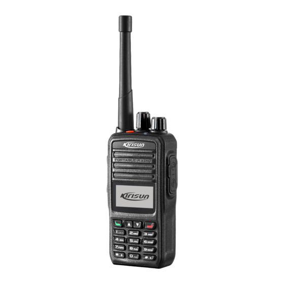
DP480 Service Manual Programmable Keys. Antenna Digital Keys External Interface Speaker Connect to an external earphone or Output voice. programming cable Programmable Key (Usually Alarm Belt Clip Key) Channel Knob Rotate it to select one from the Battery channels 1 to 16. -
Page 7: Led Indicator
DP480 Service Manual Programming Function Description Function To go back to the previous state, press the key again. Emergency On Send an emergency alarm. It is used to seek help under emergency. Emergency Off Exit emergency alarm. Under analogue channel, open voice reception path to receive weak signals. -
Page 8: Basic Operation
DP480 Service Manual 3. Basic Operation 3.1.Powering On/Off To power on the radio, rotate the Power/Volume knob clockwise until a click is heard. To power off the radio, rotate the Power/Volume knob counterclockwise until a click is heard. 3.2.Selecting a Channel When the radio is on, rotate the Channel knob to select a channel. -
Page 9: Circuit Description
DP480 Service Manual 4. Circuit Description 4.1.Circuit Diagram of Main Board... -
Page 10: Rf Circuit Diagram
DP480 Service Manual 4.2.RF Circuit Diagram 4.3.Baseband Circuit Diagram 4.4.TX Circuit The TX circuit includes an RF power amplification circuit, a low pass filter circuit and an automatic power control circuit. -
Page 11: Rx Circuit
DP480 Service Manual ⚫ RF Power Amplification Circuit RDA1846S outputs RF signal from pin 18 and enters first-level pre-drive amplifier (Q502) for initial amplification; then it enters second-level pre-drive amplifier (Q503) and drive amplifier (Q501) for further power amplification, ensuring sufficient drive power signal can be offered to final amplifier for ultimate power amplification;... -
Page 12: Power Section
DP480 Service Manual 4.6.Power Section The radio applies 7.4V lithium-ion battery for power supply. RF power amplification and audio power amplification are directly powered by battery; the battery outputs 3.6V to supply power to PMU in AT1846S and HS8861 through DC-DC switch; 3M, 3C and USB3.3V output from PMU separately supplies power to other baseband circuits;... -
Page 13: Port Description Of At1846S
DP480 Service Manual ⚫ Digital AGC ⚫ Modulation and demodulation technique based on digital signal processing technology d. TX path of direct frequency synthesis ⚫ Modulation method of direct frequency synthesis ⚫ TX filter based on digital signal processing technology ⚫... - Page 14 DP480 Service Manual MIC_IN MIC input Compensation capacitor connection AVDD Power supply No connection RFIN RF signal input AVDD Power supply No connection RFOUT RF signal output No connection No connection AVDD Power supply PABIAS PA bias supply for PA...
-
Page 15: Port Description Of Master Chip Hs8861
DP480 Service Manual (Gpio1=VH or VL, it is the input/output code data) Gpio0 / css_in / css_out GPIO0 (Gpio0=VH or VL, it is the input/output CTCSS/CDCSS signal) 4.7.3.Port Description of Master Chip HS8861 PIN NO. Port NO. Port Name Function... - Page 16 DP480 Service Manual PIN NO. Port NO. Port Name Function AB19 LCD_CS1 LCD_RST SSI0_RX SSI0_RX FLASH SSI0_TX SSI0_TX LCD/FLASH SSN0 LCD_CS SSN1 FLASH_CS FLASH GPIO_D111 NC_GPIO SSI0_CLK SSI0_CLK LCD/FLASH VOUT_D9 VIO_3V_C PMU_3V output GPIO_D76 UART_RXD0 Serial port 0 GPIO_D75 UART_TXD0...
- Page 17 DP480 Service Manual PIN NO. Port NO. Port Name Function GPIO_D47 GPIO_D50 LDAC_PC/TV DA_MCP4802 GPIO_D53 AFCO2 Speaker output MUTE GPIO_D46 RDA_PDN RDA1846S GPIO_D58 SPI/CS RDA1846S GPIO_D2 NC_GPIO GPIO_D57 SPI/CLK RDA1846S GPIO_D56 SPI/DA_OUT RDA1846S GPIO_D0 RDA_SQL GPIO_D3 KEYPAD_BL Backlight control GPIO_D107...
-
Page 18: Feature Description Of Semiconductor Devices
DP480 Service Manual PIN NO. Port NO. Port Name Function HPL_OUT MOD1 Output digital MIC signals HPR_OUT MOD2 SINK3 NC_SINK3 GPIO_D45 GPIO_D55 NC_GPIO GPIO_D59 APC_SW2 APC_SW2 GPIO_D105 NC_GPIO GPIO_D43 APC_SW1 APC_SW1 GPIO_D8 NC_GPIO GPIO_D9 QT/DQT IN QT/DQT IN GPIO_D1 LCD_BL LCD backlight control 4.7.4.Feature Description of Semiconductor Devices... -
Page 19: Feature Description And Parameter Setting
DP480 Service Manual IC100 XC6204B502 5R, 5T voltage output IC102 MP2359 3.5V voltage DC-DC output MCP4802 DA chip, used for modulation of power and frequency stability IC302 NJM2904 Operational amplifier for MIC signals 5. Feature Description and Parameter Setting 5.1.Stun, Revive and Remote Monitor Stun You can enable this function, so that the radio can be stunned after receiving a Stun command. -
Page 20: Zones
DP480 Service Manual Nuisance Delete to delete this channel before it goes on scanning. You can also add a temporary channel during scan. After exiting scan mode, the channel which is temporarily deleted or added will turn invalid. Scanning Revert Channel During radio scan, press the PTT key to enable the radio to transmit or talk on the preset channel. -
Page 21: Tot (Time-Out-Timer)
DP480 Service Manual Speech Encryption You can enable/disable speech encryption for the current channel, so that speech is sent after encryption. 5.5.TOT (Time-Out-Timer) This function is to prevent overlong channel occupation. If the radio keeps transmitting signals for a duration longer than the one set by a dealer through programming, the radio will stop transmitting and warning tone will ring. -
Page 22: Settings
The radio has been set before delivery. However, to meet customers’ requirements, it may be necessary to set such digital functions as operating frequencies, channels, DT/DQT and automatic scan. This can be achieved by the programming software CPSM Vx.xx developed by Kirisun. It is user-friendly and easy to operate, and supports Chinese and English. - Page 23 DP480 Service Manual Step 4.Click “Load file”, select the load upgrade file. The name of the selected firmware is displayed on the upgrade tool interface. Step 5.Click “Setting”, select the communication port number and the data rate “921600”.
- Page 24 DP480 Service Manual Step 6.Click “Start downloading”, start upgrade and the message “Waiting” will be displayed. Step 7.Make sure the programming cable is connected to the radio, and rotate the “Power/Volume” Knob to power on the radio. Upgrading will be started automatically.
-
Page 25: Assembly And Disassembly
DP480 Service Manual 6. Assembly and Disassembly This radio is a sophisticated communication device with precise and compact structure. Please be careful with the repair. 6.1.Installing and Uninstalling the Battery Installing the Battery Step 1.Press the upper part of the belt clip gently so that it goes up. (Figure ①) Step 2.Align the battery with the battery holder at the back of the radio, and then insert the battery. -
Page 26: Installing And Uninstalling The Antenna
DP480 Service Manual 6.2.Installing and Uninstalling the Antenna To install the antenna, insert the antenna on the top of the radio and turn it clockwise until it is fastened. To uninstall the antenna, turn it counter-clockwise to loosen it. 6.3.Installing and Uninstalling Belt Clip To install the belt clip, align the two screw holes on the belt clip with the two at the back of the radio, and fasten the clip using two 2.5*8 machine screws. -
Page 27: Detaching Shell From The Base
DP480 Service Manual 6.5.Detaching Shell from the Base Step 1. Detach the antenna; Step 2.Detach the two knobs and circlips; Step 3.Detach the two knob nuts and antenna nut; Step 4.Detach the two screws fastening the belt clip; Step 5.Insert the blade of a straight screwdriver into the battery slot of the aluminum-alloy holder, and prise the holder upwards until it goes up;... -
Page 28: Explosion Diagram
DP480 Service Manual Note: To protect the welding of the PTT PCB, please take down the board gently. After disassembly, repair and modulation can then be performed. 6.7.Explosion Diagram... - Page 29 DP480 Service Manual Material Code Material Name Specification Aluminum-alloy, wire drawing, 7PLJ-4230-E01A DP585 nameplate silver text, lead free DP480 front shell 147K01000060 PC1414, gray, etched cover 7GCB-448280-W0A Speaker dust screen Nylon net, 44.8*28.0mm*0.1mm 7MHP-4207-04A-W0 DP586 PTT cover PC1414, black, etching...
- Page 30 DP480 Service Manual Material Code Material Name Specification SUS304, 48hr salt spray test 7MHS-4245-02A-W LCD hardware holder passed M1.9*4.7 thick-head Material: harden iron, 7STF-019047B- self-tapping Phillips Φ1.9mm*4.7mm, flat-head, with SZHT-X screw guide, radiant plated M2*4 cross recessed Harden iron, Φ2mm*4mm cross...
- Page 31 DP480 Service Manual Material Code Material Name Specification ventilated lining paper and dual- sided adhesive, diameterφ7.1*φ5.3*0.3mm 7SMS-025075M- M2.5*7.5 torx M2.5*7.5 torx round-head SZYB-N1 machine screw machine screw, stainless steel O-shaped ring of Silicon rubber, outer diameter 7MHR-4072-06A-W0 power key 4mm, wire diameter 1.0mm...
-
Page 32: Debugging
DP480 Service Manual Material Code Material Name Specification DP580 numeric Silicon rubber, oil sprayed, laser 7MHR-4245-02A-W0 keyboard etching; hardness 600±5° DP586 side key cap 7MHP-4207-06A-W0 PC1414, black, etched (down) Material: PMMA/PC composite, 7MBP-4207-02A-W0 DP586 glass T=1.5; screen print at PC side 7. -
Page 33: Radio Test
DP480 Service Manual computer mode (SQL on, narrow/wide band) (five frequencies), click Ok when the value is stable. b. RF signal is set to -123dBm, modulated frequency deviation to 3.0kHz/1.5kHz (wide/narrow ban). Under computer mode (SQL off, narrow/wide band) (five frequencies), click Ok when the value is stable. -
Page 34: Equipment For Maintenance And Test
DP480 Service Manual Antenna Impedance 50Ω Microphone Impedance 2.2kΩ Battery Lithium-ion battery DC 7.4V , 2000mAh Average battery duration (5-5-90, high- Analogue channel: 18 hrs power emission), 2000mAh lithium Digital channel: 20 hrs battery Receiving Sensitivity (12dB SINAD ) -120dBm Squelch Sensitivity (3-level) ≤-120dBm... -
Page 35: Appendix 1 Abbreviations
DP480 Service Manual A. Make sure the channels the both radios communicate on are of the same frequency. Communication fails B. The radios use different CTCSS/DCS signaling codes. Set the same one via PC. C. Out of communication range. A. The antenna has bad contact. Screw up the antenna connector. - Page 36 DP480 Service Manual Intermediate frequency Light-emitting diode Low-noise amplifier Low-pass filter Micro control unit Microphone Modulation MONI Monitor Phase lock loop Push-to-talk Receiver Speaker TCXO Temperature controlled crystal oscillator Transmitter...
-
Page 37: Appendix 2 Material List (Electronic Part)
DP480 Service Manual Appendix 2 Material List (Electronic Part) Table 1 Material List of Main Board 400~470MHz Material Code Material Name Specification Position Material NO.: PJ-3511-0; 4-pin, with 133C07000002 3.5mm earphone socket J600 switch, lead free ED08E42S-FE15C7.0-A16-1020, with 3SE3-ED08E42S- Power encoder switch location column, 4.75mm axis, 15mm... - Page 38 DP480 Service Manual 41,C549,C550,C551,C553,C554,C55 9,C564,C565,C21,C333 C61,C110,C112,C115,C12,C17,C57, 2CC1-10-X7R500- MURATA,GRM155R71H103KA88D,10, 2CC1-10-X7R500-471K C58,C326,C327,C328,C329,C529,C5 103K nF,±10%,50V,0402,X7R 39,C540,C42,C49,C612 C609,C604,C101,C111,C114,C117,C 2CC1-10-X7R160- MURATA,GRM155R71C104KA88D,100 2CC1-10-X7R500-471K 5,C13,C18,C346,C56,C15,C22,C33,C 104K ,nF,±10%,16V,0402,X7R 43,C46,C616 yageo,RC0402JR-071M5L,1.5,MΩ,± 2RS1-10-155J Chip resistor C109 5%,0402 C120,C124,C526,C536,C573,C581,C 2CC1-10-X7R500- MURATA,GRM155R71H102KA01D,1,n Multi-layer chip capacitor 31,C93,C94,C95,C96,C98,C613,C61 102K F,±10%,50V,0402,X7R rohm,1SR154- 1DR1-1SR154-400 SMD rectifier diode 400,4.5mm*2.6mm*2.0mm,-55℃...
- Page 39 DP480 Service Manual 2LG1-VLS3012ET- TDK,VLS3012ET-100M,10,uH,± SMD power inductor L107 100M 20%,3*3*1.2 1TT1-KTA1298-Y R SMD transistor KEC,KTA1298-Y,SOT-23,-~150℃ Q102 Q103,Q1,Q3,Q200,Q201,Q4,Q7,Q10, 1TT1-DTC144EE R SMD transistor ROHM,DTC144EE,EMT3,-~150℃ Q606 yageo,RC0402JR-072K2L,2.2,KΩ,± 2RS1-10-222J R Chip resistor R102,R246,R247 5%,0402 R103,R110,R1,R48,R52,R53,R55,R5 yageo,RC0402JR-0710KL,10,KΩ,± 2RS1-10-103J R Chip resistor 7,R58,R59,R68,R70,R245,R601,R61 5%,0402 4,R172,R173,C611,R86 YAGEO,RC0402FR-0716K2L,16.2,KΩ,...
- Page 40 DP480 Service Manual yageo,RC0402JR-07470RL,470,Ω,± 2RS1-10-471J R Chip resistor R14,R612,R615,R622 5%,0402 C75,R43,R45,R46,R47,R71,R72,R16 7,R11,R26,R92,R251,R252,C73,C569 yageo,RC0402JR-070RL,0,Ω,± ,C570,C577,R504,R516,R555,C48,C 2RS1-10-000O R Chip resistor 5%,0402 53,R7,R20,R32,R82,R83,R88,R624,C 80,R76,R101,R112,R171,R21,IC301 (pin 2 and pin 3) yageo,RC0402JR-073K3L,3.3,KΩ,± 2RS1-10-332J R Chip resistor R56,R81 5%,0402 1IS1-MCP4802-A D/A converter IC MICROCHIP,MCP4802 2CC1-10-C0G500- MURATA,GRM1555C1H101JA01D,100...
- Page 41 DP480 Service Manual 3CF1-BL112-30RU SMD FFC/FPC connector 0.5-3-30P,lower flip connector,H=2.0 J201 L7,L9,L10,L11,L12,L13,L14,L15,L16,L 5FE1-CB100505-102 SMD EMI filter CB100505-102,1005.0 17,L18,L19,L20,L21,L22,L23,L24,L25 ,L26,L27,L28,FB1,FB17,FB20,FB41 R SMD field effect 1TF1-ST2301 Stanson,ST2301,SOT-23-3L,-~150℃ Q20,Q600 transistor yageo,RC0603JR-0722RL,22,Ω,± 2RS1-16-220J R Chip resistor R2,R5 5%,1608 yageo,RC0402FR-0768KL,68,KΩ,± 2RE1-10-6802 SMD precision resistor R104 1%,0402 yageo,RC0402JR-073KL,3,KΩ,±...
- Page 42 DP480 Service Manual ALPS,SKRTLBE010,4.5*3.55*3.3mm,- 3ST1-SKRTLBE010 SMD tact switch 40 to +90℃ memsic,MXD2020ML,LCC-8 , 1ID1-MXD2020ML Accelerometer 5.0mm*5.0mm*1.99mm,-40℃ to 105℃ 2CC1-10-X7R500- R Multi-layer chip MURATA,GRM155R71H271KA01D,270 271K capacitor ,pF,±10%,50V,0402,X7R 2CC1-10-X7R160- R Multi-layer chip MURATA,GRM155R71C473KA01D,47, C40,C16 473K capacitor nF,±10%,16V,0402,X7R 2CC1-16-C0G500- murata,GRM1885C1H330JA01D,33,pF, Multi-layer chip capacitor...
- Page 43 DP480 Service Manual 2CC1-16-C0G500- R Multi-layer chip murata,GRM1885C1H2R0CA01D,2,pF, C514 2R0C capacitor ±0.25pF,50V,1608,C0G 2CC1-16-C0G500- murata,GRM1885C1H5R0BA01D,5,pF, Multi-layer chip capacitor C515,C516 5R0B ±0.1pF,50V,1608,C0G 2CC1-16-C0G500- murata,GRM1885C1H7R0CA01D,7,pF, Multi-layer chip capacitor C517 7R0C ±0.25pF,50V,1608,C0G 2CC1-10-C0G500- R Multi-layer chip MURATA,GRM1555C1H200JA01D,20, C518 200J capacitor pF,±5%,50V,0402,C0G 2CC1-10-C0G500- R Multi-layer chip...
- Page 44 DP480 Service Manual ROHM,1SS390,1.6mm*0.8mm*0.6mm,- 1DS1-1SS390 SMD switch diode D502,D503 55℃ to 125℃ R SMD wire wound sagami,C1608CB-15NJ,15,nH,± 2LW1-16UC-150J inductor 5%,1608 R SMD wire wound sagami,C1608CB-18NJ,18,nH,± 2LW1-16UC-180J inductor 5%,1608 2LW1-20UC-8R2J SMD wire wound inductor 2012,8.2nH±5%, (C2012C-8N2J) 2LH1-R401R5-R03- R SMD air core inductor E20.40*1.5*3TL...
- Page 45 DP480 Service Manual 5FE1-BLM21P300S SMD EMI filter murata,BLM21PG300SN1D,2012.0 L512,L514 yageo,RC0603JR-0756RL,56,Ω,± 2RS1-16-560J R Chip resistor L513 5%,1608 2CC1-20-X7R500- yageo,CC0805KRX7R9BB471,470,pF, Multi-layer chip capacitor L520 471K ±10%,50V,2012,X7R 1TF1-RD07MUS2B- MITSUBISHI,RD07MUS2B-501,SLP,- SMD field effect transistor Q500 ~150℃ SMD field effect transistor 1TF1-RD01MUS2- MITSUBISHI,RD01MUS2-501,S0T-89,- (for portable digital and Q501 ~150℃...
- Page 46 DP480 Service Manual 5%,0402 yageo,RC0402JR-0756KL,56,KΩ,± 100 2RS1-10-563J R Chip resistor R509,R38 5%,0402 yageo,RC0402JR-0733RL,33,Ω,± 101 2RS1-10-330J R Chip resistor R510 5%,0402 yageo,RC0402JR-0722RL,22,Ω,± 102 2RS1-10-220J R Chip resistor R511 5%,0402 yageo,RC0603JR-07270RL,270,Ω,± 103 2RS1-16-271J R Chip resistor R515,R505 5%,1608 yageo,RC0603JR-072M2L,2.2,MΩ,± 104 2RS1-16-225J Chip resistor...
- Page 47 DP480 Service Manual YAGEO,CC0402KRX7R7BB683,68nF, 112C03000163 Ceramic capacitor ±10%,16V,0402,X7R 2CC1-10-C0G500- R Multi-layer chip MURATA,GRM1555C1H100JA01D,10, 100D capacitor pF,±5%,50V,0402,C0G murata,GRM219R6J475KE19D,4.7,uF, 2CC1-20-X7R6R3- R Multi-layer chip ±10%,6.3V,2012,X7R,高度 0.85± C50,C51,C617 475K capacitor 0.1MM YAGEO,CC0603JRNPO9BN102,1nF,± 112C03000141 Ceramic capacitor C52,C97 5%,50V,0603,NPO 3FW1-0805L035 SMD fuse Littelfuse,0805L035,0603,-40 to +85℃ C85,C605 1.25mm 4PIN,1.25mm 4PIN,-25°C to...
- Page 48 DP480 Service Manual yageo,RC0402JR-07470KL,470,KΩ,± 125 2RS1-10-474J R Chip resistor 5%,0402 yageo,RC0402JR-075K6L,5.6,KΩ,± 126 2RS1-10-562J R Chip resistor R613 5%,0402 yageo,RC0402JR-071K8L,1.8,KΩ,± 127 2RS1-10-182J R Chip resistor R618 5%,0402 yageo,RC0402JR-0739KL,39,KΩ,± 128 2RS1-10-393J R Chip resistor R631 5%,0402 129 1IS1-TDA2822 SMD IC UTC,TDA2822,SOP8,-20 to +85℃...
- Page 49 DP480 Service Manual 137 1IS1-AT2659 Low noise amplifier AT2659,1550MHz~1615MHz,6pinDFN Temperature compensated 138 125O03000001 2TG2600001, X101 crystal oscillator 32.768KHz,+20.0-20.0,FC- 139 135X02000005 Crystal resonator 135,Q13FC13500002,7P,3.2mm*1.5mm ,EPSON 140 6PM7-4237-HMC 106*47MM, mainboard,1.0mm,4.0,FR4 Copper-Nickel-Zinc alloy,original 141 7MDC-4207-02A-W GPS shield cover color,0.2mm thick,33*13.05*3 Automatic power control...
- Page 50 DP480 Service Manual Table 2 Material List of Main Board 137~174MHz Material Code Material Name Specification Position Material NO.: PJ-3511-0; 4-pin, with 133C07000002 3.5mm earphone socket J600 switch, lead free ED08E42S-FE15C7.0-A16-1020, 3SE3-ED08E42S- Power encoder switch with location column, 4.75mm axis,...
- Page 51 DP480 Service Manual Copper-Nickel-Zinc alloy, original 7MDC-4207-04A-W Power shield cover color, 0.2mm thick, 16.2*15.1*2.3 7PLJ-025006-T01A High temperature sticker 25*6mm C28,C47,C103,C108,C119,C123,C20 2CC1-20-X5R160- EMK212ABJ106KD-T,2012,10uF± Multi-layer chip capacitor ,C39,C91,C106,C582,C86,C606,C61 106KD 10%,16V,TAIYO,0.85±0.1mm high 5,C312,C315 C55,C102,C104,C113,C118,C122,C1 4,C64,C65,C66,C67,C230,C231,C23 2,C233,C332,C107,C522,C523,C528 2CC1-10-X7R500- murata,GRM155R71H471KA01D,4 ,C530,C531,C532,C533,C537,C538, R Multi-layer chip capacitor 471K 70,pF,±10%,50V,1005,X7R...
- Page 52 DP480 Service Manual to 150℃ SD103AW,SOD-323, 121D03000007 SMD Schottky barrier diode 2.7mm*1.35mm*1.0mm,-55℃ to D101 150℃, littelfuse,429003/433003/466003,3 3FW1-42932-302320 SMD fuse F100 216,3A/32V 1IS1- R SMD voltage regulator IC XC6204B502MR,SOT-25,-40~85° IC100 XC6204B502MR MPS,MP2359,TSOT23-6,-40 to 1IS1-MP2359 SMD switch power supply IC IC102 +85℃...
- Page 53 DP480 Service Manual YAGEO,RC0402FR- 2RE1-10-1602 SMD precision resistor R106 0716K2L,16.2,KΩ,±1%,0402 yageo,RC0402JR-07100KL,100,K 2RS1-10-104J R Chip resistor R107,R526,R105,R63 Ω,±5%,0402 R108,R3,R50,R236,R237,R238,R239 yageo,RC0402JR-071KL,1KΩ,± 2RS1-10-102J R Chip resistor ,R6,R10,R502,R539,R544,R545,R54 5%,0402 7,R551,R560,R623,R60 2CC1-10-X7R160- MURATA,GRM155R71C333KA01D R Multi-layer chip capacitor C99,C100,C125,C583 333K ,33,nF,±10%,16V,0402,X7R C105,C126,C127,R61,R62,C313,C31 2CC1-10-X5R100- MURATA,GRM155R61A474KE15D R Multi-layer chip capacitor...
- Page 54 DP480 Service Manual ±5%,0402 1IS1-MCP4802-A D/A converter IC MICROCHIP,MCP4802 2CC1-10-C0G500- MURATA,GRM1555C1H101JA01D R Multi-layer chip capacitor C24,C324,C325,C1,C2 101J ,100,pF,±5%,50V,0402,C0G yageo,RC0805JR-070RL,0,Ω,± 2RS1-20-000O R Chip resistor C337 5%,2012 ,HJ-19URC- 124P01000006 SMD light emitting diode T6,red,2V@20mA,1.6mm*0.8mm*0 D203 .6mm,-40~85°C, HJ-19YGC-T6, 124P01000007 SMD light emitting diode chartreuse,2V@20mA,1.6mm*0.8m...
- Page 55 DP480 Service Manual ALPS,SKRTLBE010,4.5*3.55*3.3m 3ST1-SKRTLBE010 R SMD tact switch m,-40 to +90℃ 2CC1-10-X7R500- MURATA,GRM155R71H271KA01D R Multi-layer chip capacitor 271K ,270,pF,±10%,50V,0402,X7R 2CC1-10-X7R160- MURATA,GRM155R71C473KA01D R Multi-layer chip capacitor C40,C16 473K ,47,nF,±10%,16V,0402,X7R 2CC1-10-C0G500- MURATA,GRM1555C1H470JA01D R Multi-layer chip capacitor C73,C54 470J ,47,pF,±5%,50V,0402,C0G 2CC1-10-C0G500- MURATA,GRM1555C1H1R0CA01...
- Page 56 DP480 Service Manual 2CC1-10-C0G500- MURATA,GRM1555C1H820JA01D R Multi-layer chip capacitor C512 820J ,82,pF,±5%,50V,0402,C0G 2CC1-16-C0G500- murata,GRM1885C1H8R0DA01D,8 R Multi-layer chip capacitor C513,C517 8R0D ,pF,±0.5pF,50V,1608,C0G 2CC1-16-C0G500- murata,GRM1885C1H200JA01D,2 R Multi-layer chip capacitor C515 200J 0,pF,±5%,50V,1608,C0G 2CC1-16-C0G500- murata,GRM1885C1H220JA01D,2 R Multi-layer chip capacitor C516 220J 2,pF,±5%,50V,1608,C0G 2CC1-10-C0G500-...
- Page 57 DP480 Service Manual 2CC1-10-X7R500- MURATA,GRM155R71H153KA12D R Multi-layer chip capacitor C547 153K ,15,nF,±10%,50V,0402,X7R 2CC1-10-C0G500- MURATA,GRM1555C1H6R0CA01 R Multi-layer chip capacitor C561 6R0C D,6,pF,±0.25pF,50V,0402,C0G 2CC1-10-C0G500- MURATA,GRM1555C1H151JA01D R Multi-layer chip capacitor C573 151J ,150,pF,±5%,50V,0402,C0G yageo,RC0402JR-07560RL,560,Ω, 2RS1-10-561J R Chip resistor C578 ±5%,0402 2CC1-10-X7R250- MURATA,GRM155R71E223KA61D R Multi-layer chip capacitor...
- Page 58 DP480 Service Manual 2LH1-R301R5-R07- SMD air core inductor E20.3*1.5*7TL L501,L505 2LH1-R301R5-L06- R SMD air core inductor E20.3*1.5*6TR L502,L503 SunLord,SDCL1608C2N2STDF,2.2 2LL1-16-2N2SB Multi-layer chip inductor L504 ,nH,±0.3nH,1608 2520,1μH±5%, 2LW1-25UC-102JA R SMD wire wound inductor L506,L508 (FHW1008UC1R0J) 2LH1-R401R5-R08- R SMD air core inductor E20.40*1.5*8TL...
- Page 59 DP480 Service Manual TOSHIBA,2SC5108-Y,2-2H1A,- 1TT1-2SC5108-Y R SMD transistor Q502 ~125℃ LRC,L2SC3356LT1,SOT-23,- 1TT1-L2SC3356LT1 SMD transistor Q503 ~150℃ yageo,RC0603JR-0733KL,33,KΩ, 2RS1-16-333J R Chip resistor ±5%,1608 yageo,RC0603JR-0710KL,10,KΩ, 2RS1-16-103J R Chip resistor ±5%,1608 yageo,RC0402JR-074K7L,4.7,KΩ, 2RS1-10-472J R Chip resistor R39,R561,R562 ±5%,0402 yageo,RC0603FR-07220KL,220,K 2RE1-16-2203 SMD precision resistor Ω,±1%,0603...
- Page 60 DP480 Service Manual yageo,RC0402JR-0722RL,22,Ω,± 2RS1-10-220J R Chip resistor R511 5%,0402 yageo,RC0603JR-072M2L,2.2,M 2RS1-16-225J Chip resistor R517 Ω,±5%,1608 yageo,RC0603FR-07150KL,150,K 2RE1-16-1503 R SMD precision resistor R518,R525 Ω,±1%,0603 yageo,RC1206JR-070R39L,0.39, 2RS1-32-R39J R Chip resistor R520,R521,R522,R523 Ω,±5%,3216 yageo,RC0603FR-07100KL,100,K 2RE1-16-1003 SMD precision resistor R527,R528 Ω,±1%,0603 yageo,RC0402JR-0720KL,20,KΩ, 2RS1-10-203J...
- Page 61 DP480 Service Manual YAGEO,CC0603JRNPO9BN102,1n 112C03000141 Ceramic capacitor C52,C97 F,±5%,50V,0603,NPO Littelfuse,0805L035,0603,-40 to 3FW1-0805L035 SMD fuse C85,C605 +85℃ 1.25mm 4PIN,1.25mm 4PIN,-25° 3CF1-SMT-4P SMT connector C to 85°C TOSHIBA,2SC4116-GR,SOT- 1TT1-2SC4116-GR R SMD transistor 323/SC-70,-~125℃ Stanson,ST2301,SOT-23-3L,- 1TF1-ST2301 R SMD field effect transistor Q600,Q20 ~150℃...
- Page 62 DP480 Service Manual yageo,RC0402JR-074R7L,4.7,Ω, 2RS1-10-4R7J R Chip resistor R84,R85 ±5%,0402 yageo,RC0402JR-075K6L,5.6,KΩ, 2RS1-10-562J R Chip resistor R613 ±5%,0402 yageo,RC0402JR-071K8L,1.8,KΩ, 2RS1-10-182J R Chip resistor R618 ±5%,0402 yageo,RC0402JR-0739KL,39,KΩ, 2RS1-10-393J R Chip resistor R631 ±5%,0402 1IS1-TDA2822 SMD IC UTC,TDA2822,SOP8,-20 to +85℃ U600 2CC1-10-C0G500- MURATA,GRM1555C1H6R8CA01...
- Page 63 DP480 Service Manual SunLord,SDCL1608C8N2JTDF,8.2, 2LL1-16-8N2DA Multi-layer chip inductor nH,±0.5nH,1608 121I05000092 SMD IC AT6558F-5N32, AT2659,1550MHz~ 1IS1-AT2659 Low noise amplifier 1615MHz,6pinDFN Temperature compensated 125O03000001 2TG2600001, X101 crystal oscillator 32.768KHz,+20.0-20.0,FC- 135X02000005 Crystal resonator 135,Q13FC13500002,7P,3.2mm*1. 5mm,EPSON YAGEO,RC0402FR-0722KL,22,K 2RE1-10-2202 SMD precision resistor Ω,±1%,0402 0.5-3-30P,lower flip...
- Page 64 DP480 Service Manual Table 3 Material List of Module Board HS8861 Material NO. Material Name Specification Position EMK212ABJ106KD-T,2012,10uF 2CC1-20-X5R160- ±10%,16V,TAIYO,0.85±0.1mm multi-layer chip capacitor C1,C17,C18,C37,C38 106KD high yageo,RC0201JR-0733RL,33,Ω, chip resistor 2RS1-06-330J R29,R30,R31,R32 ±5%,0201 R multi-layer chip 2CC1-10-X7R500- MURATA,GRM155R71H102KA01 C3,C10,C9,C15,C34,C36 capacitor 102K D,1,nF,±10%,50V,0402,X7R...
- Page 65 DP480 Service Manual to 125℃ rectifier diode 121D03000006 ROHM,RB706UM-40, yageo,RC0603JR-070RL,0,Ω,± R chip resistor 2RS1-16-000O FB105 5%,1608 韦尔,WS72321B-5/TR,SOT353,-40 linear IC 121I04000023 to +125℃, yageo,RC0402JR-0710KL,10,KΩ, 2RS1-10-103J R chip resistor R1,R12,R15,R16,R17,R18 ±5%,0402 yageo,RC0402JR-071KL,1KΩ,± 2RS1-10-102J R chip resistor R3,R7,R8 5%,0402 yageo,RC0402JR-070RL,0,Ω,± 2RS1-10-000O R chip resistor...
- Page 66 DP480 Service Manual Natlinear,LN1121P332MR,SOT23- SMD voltage regulator IC 1IS1-LN1121P332MR U1,U3,U4 3,-40 to +85℃ Storage IC 121I02000005 W25Q64JVZEIQ,2.7-3.6V, U0005 HS8861;175;TFBGA;7.8X7.8;040; 121I01000003 MCU+baseband IC U2100 Temperature 5OT1-26R0- KDS,1XXB26000MAA,26MHz± compensated crystal DSB221SDN 0.5ppm,2520 oscillator DP405W_MODULE,36.4X24.7mm, 136P04000077 4-layer,1.0mm ROHM,1SS390,1.6mm*0.8mm*0.6 SMD switch diode 1DS1-1SS390 D105 mm,-55℃...
-
Page 67: Appendix 3 Material List (Structural Section)
DP480 Service Manual Spacing 0.5 mm, 16-pin, BL112- SMD FFC/FPC 3CF1-BL112-16RL 16RL, horizontal type, bottom connector contact, with lock SMD light emitting diode D1,D2,D3,D4,D5,D6,D7,D8 124P01000008 19-217/W1D-APQHY/3T,0603 2RS1-10-101J R chip resistor 1005,100Ω±5% R1,R2,R3,R4 DP580-KEY, size: 6PM7-4245-HKB DP580 key PCB 45.45x36.2mm, thickness: 0.8MM, 4-layer, FR-4, lead free... - Page 68 DP480 Service Manual Material NO. Material Name Specification 3CR7-SMA-50JF-4 RF coaxial cable SMA-J, flange, 7200 times of use 7NRC-4078-01A-N Antenna connector nut Brass, black nickel plated, lead free 7SMF-020040M-SZYB- R M2*4 cross recessed mushroom- Harden iron, Φ2mm*4mm cross recessed mushroom-head...
-
Page 69: Appendix 4 Accessory List
DP480 Service Manual Material NO. Material Name Specification DP485 waterproof pad for earphone 7MHP-4253-04A-W0 TPU, black, etched, lead free jack R 558 rubber pad for shrapnel at Material: silicon rubber, hardness 40°, black, no surface 7MHR-1727-08A-W0 battery anode/cathode treatment 7GCM-150120025-J Sponge mat for battery 5*12*2.5mm, single-sided adhesive, black... -
Page 70: Appendix 5 Schematic Diagrams And Layout Drawings
DP480 Service Manual Appendix 5 Schematic Diagrams and Layout Drawings Schematic Diagrams of Main Board XC6204B502MR IC100 L100 Q102 ST2301 BLM11A601S C101 100nF C102 R103 R102 C104 470P C103 10uF 470P 2.2K Q103 DTC144EE RF_4V2 BLM11A601S 10uF C108 10nF 10uF... - Page 71 DP480 Service Manual RED_LED LDAC_PC/TV ENC_0 PF_KEY1 LDAC SPI_DA_OUT PTT_KEY VOUTB VCCN SPI_CLK GREEN_LED DACS_SW1 ENC_1 VOUTA KEYPAD_BL RDA_SQL R167 MCP4802 SPI_DA_OUT 0Ω SPI_CLK C346 PF_KEY2 100nF SPI_/CS RDA_PDN AFCO_2 LDAC_PC/TV DACS_SW1 AFCO_1 AF_OUT R56 3.3K INPA 470nF BEEP_OUT C105 C126 470Ω...
- Page 72 DP480 Service Manual ST2301 10nF PF_KEY0 PTT_KEY 100K PF_KEY1 PF_KEY2 SIDEKEY MAND_C 10nF 10Ω TOUT DOUTY MAND E1_1 VREF AUDIO_ENC0 DOUTX E1_3 AUDIO_ENC1 100nF E2_3 AUDIO_ENC2 MXD2020ML E2_1 AUDIO_ENC3 S200 C332 MOD_RDA1846 470P R237 L300 E1_1 ENC_0 BLM11A601S R236 ENC_1...
- Page 73 DP480 Service Manual C503 C504 C505 C506 C510 D500 C511 RN142S 8.2nH L500 3T L501 L503 120P L502 CN500 Q500 L504 C515 C517 C512 C509 L505 TO ANT RD07MUS2B C513 C516 2.7nH D501 2.5P RN142S C521 L510 Q501 C520 R503...
- Page 74 DP480 Service Manual Q600 ST2301 10nF 100nF R601 10uF 0Ω AFCO_1 DTC144EE J600 C603 R15 NC 1000P 0Ω C26 NC C605 0Ω BEEP_OUT C135 R603 C604 Fuse 100nF C606 R604 470K MIC+ 10uF 1000P 1000P INPUT2 OUTPUT2 4.7Ω R607 4pin...
- Page 75 DP480 Service Manual UBX-M8030 U-BLOX G7 X101 26MHz 8.2nH C80 0Ω GPS_LNA LNA_IN XTAL_I R101 0Ω XTAL_O OE 1 2.5P FB42 LDO_X_OUT GND1 R109 SCL2 TXD1 RXD1 C142 SDA2 RXD1 TXD1 R172 FB43 TIMEPULSE T_SENSE C325 C324 VCC_RF EXTINT0 100P...
-
Page 76: Top-Layer Layout Drawing Of Main Board Dp480
DP480 Service Manual Top-Layer Layout Drawing of Main Board... -
Page 77: Bottom-Layer Layout Drawing Of Main Board Dp480
DP480 Service Manual Bottom-Layer Layout Drawing of Main Board... -
Page 78: Schematic Diagram Of Key Pcb Dp480
DP480 Service Manual Schematic Diagram of Key PCB DP586_KEY_CON_KEYBOAR FP560_LCD_CO LCD_DATA 100Ω LCD_0 D ATA LCD_1 100Ω C 1 1 ATA2 5 L CD_ DATA LCD_ DATA 4 L CD_ DATA LCD_5 7 8 S DATA6 6 V DD CD_DATA7... -
Page 79: Top-Layer Layout Drawing Of Key Pcb Dp480
DP480 Service Manual Top-Layer Layout Drawing of Key PCB... -
Page 80: Bottom-Layer Layout Drawing Of Key Pcb Dp480
DP480 Service Manual Bottom-Layer Layout Drawing of Key PCB... -
Page 81: Schematic Diagrams Of Module Board Hs8861
DP480 Service Manual Schematic Diagrams of Module Board U2100-A DIGTAL 1 of 3 RF (VDD28) 5T_EN 5T_EN 5R_EN 5R_EN APC_SW1 PC_SW KEYPAD (VDD28) KEYOUT0 KEYOUT0 KEYOUT1 KEYOUT1 TP10 KEYOUT2 KEYOUT2 TP11 TP79 SPI LCM (VLCM) KEYOUT3 KEYOUT3 TP12 APC_SW2 FMARK... - Page 82 DP480 Service Manual U2100-B ANALOG 2 of 3 AUDIO MBIAS BT_TRX MIC_P MICP MIC_N MICN FM_LANT [2] HEADMIC_P 2520 封装 HEADMICP FM_SANT [2] HEADMIC_N HEADMICN VBAT_3V6 HEADMIC_IN SPK_P TP65 [2] HE_L HEADP_L VOUT OUTPUT XO_P HEADP_R [2] HE_R LN1121P332MR C153...
- Page 83 DP480 Service Manual VBAT_3V6 U2100-C POWER/GND 3 of 3 VBAT VB (FROM VBATB) VBATA (150mA) AVDDVBO AVDDVB VDDRF0 AVDDVB VBATB LDO OUT (VBATB) (200mA) VDDRF VBATPA (150mA) VDD18 CHARGE (150mA) VDD28 VDD2V8 VBAT_SENSE VBAT_ADC (150mA) VDDCORE TP26 这个替换之前 3 号引脚...
-
Page 84: Top-Layer Layout Drawing Of Module Board Hs8861
DP480 Service Manual Top-Layer Layout Drawing of Module Board...
Need help?
Do you have a question about the DP480 and is the answer not in the manual?
Questions and answers