Table of Contents
Advertisement
Available languages
Available languages
Quick Links
Camille Bauer AG
Betriebsanleitung
Messumformer für Phasenwinkel oder
Leistungsfaktor SINEAX G 536
Mode d'emploi
Convertisseur de mesure pour l'angle de phase
ou facteur de puissance SINEAX G 536
Operating Instructions
Transducer for phase angle or power factor
SINEAX G 536
G 536 B d-f-e
Aargauerstrasse 7
CH-5610 Wohlen/Switzerland
Telefon +41 56 618 21 11
Telefax +41 56 618 24 58
e-mail: cbag@gmc-instruments.com
http://www.gmc-instruments.com
130 865
01.01
1
Advertisement
Chapters
Table of Contents

Related Manuals for Camille Bauer SINEAX G 536


Summary of Contents for Camille Bauer SINEAX G 536
- Page 1 Messumformer für Phasenwinkel oder Leistungsfaktor SINEAX G 536 Mode d’emploi Convertisseur de mesure pour l’angle de phase ou facteur de puissance SINEAX G 536 Operating Instructions Transducer for phase angle or power factor SINEAX G 536 G 536 B d-f-e 130 865 01.01...
-
Page 3: Table Of Contents
2. Kurzbeschreibung Hilfsenergie ab Mess- eingang (self powered): ≥ 24 - 60 V AC oder 85 - 230 V AC, Der Umformer SINEAX G 536 misst den Phasenwinkel oder siehe Bild 3 Leistungsfaktor zwischen Strom und Spannung eines Ein- phasennetzes oder eines symmetrisch belasteten Drei- Max. -
Page 4: Befestigung
… dass die Messausgangsleitungen als verdrillte 4. Befestigung Kabel und möglichst räumlich getrennt von Starkstromleitungen verlegt werden! Die Befestigung des SINEAX G 536 erfolgt auf einer Hut- schiene. Im übrigen landesübliche Vorschriften (z.B. für Deutschland VDE 0100 «Bedingungen über das Bei der Bestimmung des Montageortes müs-... -
Page 5: Inbetriebnahme Und Wartung
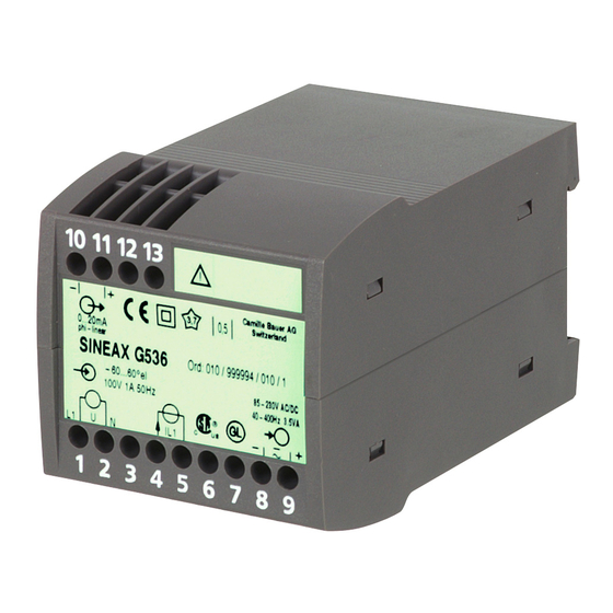
12 13 7. Demontage-Hinweis – Messumformer gemäss Bild 6 von Tragschiene abnehmen. 4-20mA cosphi-linear Prüfzeichen SINEAX G 536 Mat: 126830 / 0000000 0.5 - cap - 1 - ind - 0.5 85-230V DC/AC 230V 5A 50Hz Fabrikations- 40-400Hz 3.5VA Nummer I L1 –... -
Page 6: Mass-Skizze
8. Mass-Skizze 112,5 12 13 114,1 Bild 7. Gehäuse P13/70 auf Hutschiene (35 × 15 mm oder 35 × 7,5 mm, nach EN 50 022) aufgeschnappt. 9. Anwendungen Stromanschluss in Phase Spannungsanschluss L1 & L2 L2 & L3 L3 & L1 L1 &... -
Page 7: A Lire En Premier, Ensuite
Alimentation auxiliaire de l’entrée de mesure ≥ 24 - 60 V CA ou 85 - 230 V CA, Le convertisseur de mesure SINEAX G 536 détermine l’angle (self powered): de phase ou le facteur de puissance entre un courant et une voir Fig. -
Page 8: Fixation
… que les lignes de sortie de signal de mesure 4. Fixation soient réalisées par des câbles torsadés et Les SINEAX G 536 peuvent être montés sur des rails «à disposées à une certaine distance des lignes chapeau». courant fort! Au reste, respecter les prescriptions nationales En déterminant l’emplacement de montage, il... -
Page 9: Mise En Service Et Entretien
7. Instructions pour le démontage 4-20mA cosphi-linear Repères de test Démonter le convertisseur du rail support selon Fig. 6. SINEAX G 536 Mat: 126830 / 0000000 0.5 - cap - 1 - ind - 0.5 85-230V DC/AC 230V 5A 50Hz No de 40-400Hz 3.5VA... -
Page 10: Croquis D'encombrement
8. Croquis d’encombrement 112,5 12 13 114,1 Fig. 7. Boîtier type P13/70 encliqueté sur rail «à chapeau» (35 × 15 mm ou 35 × 7,5 mm, selon EN 50 022). 9. Recommandations pratiques Circuit d’intensité dans phase Circuit de tension L1 &... -
Page 11: Read First And Then
Operating Instructions Transducer for phase angle or power factor SINEAX G 536 Within – 180 - 0 - + 180 °el or Measuring range: Safety precautions to be strictly observed are marked –1-ind-0-cap-1-ind-0-cap- –1 with following symbols in the Operating Instructions: but clear indication only to –175-0- +175 °el... -
Page 12: Mounting
4. Mounting from heavy current cables! In all other respects, observe all local regulations The SINEAX G 536 can be mounted on a top-hat rail. when selecting the type of electrical cable and installing them! Note “Environmental conditions” in Section “3. -
Page 13: Commissioning And Maintenance
No maintenance is required. – 7. Releasing the transducer 4-20mA cosphi-linear Test marks SINEAX G 536 Release the transducer from a top-hat rail as shown in Mat: 126830 / 0000000 0.5 - cap - 1 - ind - 0.5 Fig. 6. 85-230V DC/AC 230V 5A 50Hz Works No. -
Page 14: Dimensional Drawing
8. Dimensional drawing 112.5 12 13 114.1 Fig. 7. Housing P13/70 clipped onto a top hat rail (35 × 15 mm or 35 × 7.5 mm, acc. to EN 50 022). 9. Application notes Current connection in phase Voltage connection L1 &...
Need help?
Do you have a question about the SINEAX G 536 and is the answer not in the manual?
Questions and answers