Table of Contents
Advertisement
Available languages
Available languages
Quick Links
Camille Bauer AG
Aargauerstrasse 7
CH-5610 Wohlen/Switzerland
Telefon +41 56 618 21 11
Telefax +41 56 618 35 35
e-mail: info@camillebauer.com
http://www.camillebauerag.com
Betriebsanleitung
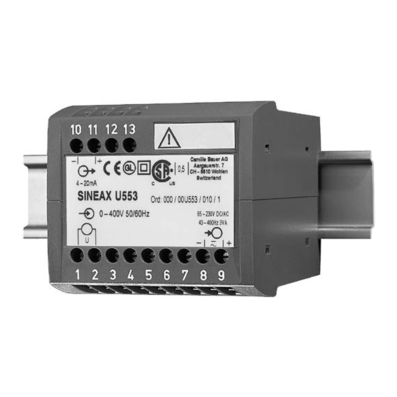
Messumformer für Wechselspannung SINEAX U 553
Mode d'emploi
Convertisseur de mesure
pour tension alternative SINEAX U 553
Operating Instructions
Transducer for AC voltage SINEAX U 553
U 553 B d-f-e
131 251-01
09.05
1
Advertisement
Chapters
Table of Contents

Related Manuals for Camille Bauer SINEAX U553


Summary of Contents for Camille Bauer SINEAX U553
- Page 1 SINEAX U 553 Operating Instructions Transducer for AC voltage SINEAX U 553 U 553 B d-f-e 131 251-01 09.05 Camille Bauer AG Aargauerstrasse 7 CH-5610 Wohlen/Switzerland Telefon +41 56 618 21 11 Telefax +41 56 618 35 35 e-mail: info@camillebauer.com...
-
Page 3: Table Of Contents
Betriebsanleitung Messumformer für Wechselspannung SINEAX U 553 Messausgang Sicherheitshinweise, die unbedingt beachtet werden Gleichstrom: 0(0,2) - 1 bis 0(4) - 20 mA müssen, sind in dieser Betriebsanleitung mit folgenden Bürdenspannung: 15 V Symbolen markiert: 15 V max. [kΩ] ≤ Aussenwiderstand: [mA] = Ausgangsstromendwert Gleichspannung:... -
Page 4: Befestigung
4. Befestigung – + Die Befestigung des SINEAX U 553 erfolgt auf einer Hut- schiene. – + – Bei der Bestimmung des Montageortes müs- sen die «Umgebungsbedingungen», Abschnitt 12 13 12 13 «3. Technische Daten», eingehalten werden! Gehäuse auf Hutschiene (EN 50 022) aufschnappen (siehe Bild 1). -
Page 5: Messbereich-Einstellbarkeit Durch Dc-Kalibrierung
6. Messbereich-Einstellbarkeit durch P201 P200 KP1 (–) KP2 (+) DC-Kalibrierung Die DC-Kalibrierung erfolgt auf eigene 10 11 12 13 Verantwortung. Beim Entfernen des Ab- stimmsiegels erlischt die Garantie. – Messeingang unbedingt sicher von gefähr- licher Spannung trennen. 4-20mA Einstellbarkeit: Zulässige Änderung des Messbe- reich-Endwertes, variable Empfind- Bild 6. -
Page 6: A Lire En Premier, Ensuite
Mode d’emploi Convertisseur de mesure pour tension alternative SINEAX U 553 Sortie de mesure Les conseils de sécurité qui doivent impérativement Courant continu: 0(0,2) - 1 à 0(4) - 20 mA être observés sont marqués des symboles ci-contre Tension de charge: 15 V dans le présent mode d’emploi: 15 V... -
Page 7: Fixation
4. Fixation – + Les SINEAX U 553 peuvent être montés sur des rails «à chapeau». – + – En déterminant l’emplacement de montage, il faut tenir compte des indications fournis sous 12 13 12 13 la rubrique «Ambiance extérieure» du chapitre «3. -
Page 8: Ajustage De L'étendue De Mesure Par
6. Ajustage de l’étendue de mesure par cali- P201 P200 KP1 (–) KP2 (+) brage en CC La calibration CC se réalise aux risques de l’utilisateur. En enlevant le cache 10 11 12 13 couvrant les organes d’ajustage, la garantie s’éteint. -
Page 9: Read First And Then
Operating Instructions Transducer for AC voltage SINEAX U 553 Measuring output Safety precautions to be strictly observed are marked DC current: 0(0.2) - 1 to 0(4) - 20 mA with following symbols in the Operating Instructions: Burden voltage: 15 V 15 V max. -
Page 10: Mounting
4. Mounting – + The SINEAX U 553 can be mounted on a top-hat rail. – + – Note “Environmental conditions” in Section “3. Technical data” when determining the place of installation! 12 13 12 13 Simply clip the device onto the top-hat rail (EN 50 022) (see Fig. -
Page 11: Adjustable Measuring Range By Dc Calibration
6. Adjustable measuring range by DC calibra- P201 P200 KP1 (–) KP2 (+) tion DC calibration is performed at the user’s 10 11 12 13 risk. The warranty is void if the calibration seal is removed. – Reliably isolate the measuring input from dangerous voltages. -
Page 12: Mass-Skizze
(35 ×15 mm or 35×7.5 mm, acc. to EN 50 022). 114.1 11. Konformitätserklärung / 11. Certificat de conformité / 11. Declaration of conformity EG - KONFORMITÄTSERKLÄRUNG DECLARATION OF CONFORMITY Dokument-Nr./ U553.DOC Document.No.: Camille Bauer AG Hersteller/ Manufacturer: Switzerland Anschrift / Aargauerstrasse 7 Address: CH-5610 Wohlen Messumformer für Wechselspannung mit Hilfsenergie-Anschluss...
Need help?
Do you have a question about the SINEAX U553 and is the answer not in the manual?
Questions and answers