Advertisement
Quick Links
- Wiring Brochure
Universal Reset Module 422
1
2
Information
Application
Brochure
Brochure
Choose controls
Design your
to match
mechanical
application
applications
Introduction
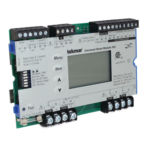
The following wiring brochure describes how to wire the tekmar Universal Reset Module 422. The 422 is to be installed
in an enclosure together with a tekmar Zone Manager. The 422 controls one boiler (on-off or modulating), DHW, setpoint
and one mixing (either variable speed injection or floating action). The wiring of tekmarNet
and cost effective.
Boiler
DHW
Setpoint
Demand
Demand
24 V (ac) Boil/Mix2
51 52
53 54 55
56
57
Output 1 VA
Menu
/
Item
tN4 Boiler / Mix 2
Boil Sens Sup / Ret
Boiler On-Off / Mod
Off / tekmar Stager
Off / Flushing
Meets Class B: Canadian
ICES & FCC Part 15
Made in Canada
Test
71
72
DHW
Pump
N
Var. Pump Fuse
T2.5 A 250 V
3
Rough-in
Wiring
Rough-in
wiring
instructions
C
R
C2 tN4
Floating Output:
24 V (ac) 8 VA
58
59
60
Universal Reset Module 422
2.5 A
73
74
Variable Speed
Pump
N
4
Wiring
Brochure
Wiring and
installation of
specific control
C
Opn Cls
+
–
Com Boil Mix Com Out
R
R
Mod (dc)
61
62
63 64
65
66
67
68
69
Powered Output
Do not apply power
tN4
tektra 991-03
Var. Pump: 115 V (ac) 2.5 A
Demands: 20 - 260 V (ac)
Relay Rating: 115 V (ac) 5 A
75
76
77
78
Primary
Mix Sys P1
Pump
N
Pump
N
1 of 12
5
6
Data
Brochure
Control settings
and sequence of
operation
4 (tN4) components is simple
®
70
tekmar wiring Enclosure (not included)
10 A
max.
tekmar Zone Manager
© 2009
W 422
03/09
Job
Record
Record settings &
wiring details for
future reference
W 422 - 03/09
Advertisement

Subscribe to Our Youtube Channel
Related Manuals for Tekmar Universal Reset Module 422


Summary of Contents for Tekmar Universal Reset Module 422
- Page 1 Introduction The following wiring brochure describes how to wire the tekmar Universal Reset Module 422. The 422 is to be installed in an enclosure together with a tekmar Zone Manager. The 422 controls one boiler (on-off or modulating), DHW, setpoint and one mixing (either variable speed injection or floating action).
- Page 2 Table of Contents Wiring Symbols & Definitions ........2 Troubleshooting Instructions ........9-11 Module Installation ............3 Technical Data .............. 12 Electrical Drawings ............4-7 Wiring Specification Guide ........... 12 Wiring the Control ............8-9 Wiring Symbols Demand, signals control to operate. Requires a power and neutral connection. Use 24 Fuse, field replaceable.
- Page 3 Module Installation Install the Universal Reset Module 422 in the left side of a tekmarNet ® 4 (tN4) wiring enclosure. The enclosure comes with a Zone Manager pre-installed in the right side. Review the figure below to understand the installation of the 422: To Install the 422 1.
- Page 4 24 V (ac) 8 VA 51 52 53 54 55 63 64 Output 1 VA Powered Output Do not apply power Universal Reset Module 422 Menu Item Connections tN4 Boiler / Mix 2 tektra 991-03 Boil Sens Sup / Ret...
- Page 5 24 V (ac) 8 VA 51 52 53 54 55 63 64 Output 1 VA Powered Output Do not apply power Universal Reset Module 422 Menu Item Connections tN4 Boiler / Mix 2 tektra 991-03 from Zone Boil Sens Sup / Ret D 422 Boiler On-Off...
- Page 6 24 V (ac) 8 VA 51 52 53 54 55 63 64 Output 1 VA Powered Output Do not apply power Universal Reset Module 422 Menu Item Connections tN4 Boiler / Mix 2 tektra 991-03 from Zone Boil Sens Sup / Ret D 422 Boiler On-Off...
- Page 7 24 V (ac) 8 VA 51 52 53 54 55 63 64 Output 1 VA Powered Output Do not apply power Universal Reset Module 422 Menu Item Connections tN4 Boiler / Mix 2 tektra 991-03 from Zone Boil Sens Sup / Ret D 422 Boiler On-Off...
- Page 8 The following section explains how to wire individual terminals. devices to the Universal Reset Module 422. For step by • • Refer to the current and voltage ratings at the back step wiring refer to the terminal number on the right of of this brochure before connecting devices to this the page.
- Page 9 Note: Some modulating boilers may also require an on / • • The control provides a 0-10 V (dc) modulating output to a single modulating boiler or to a tekmar boiler staging off signal in addition to the modulating signal. See terminals control that accepts an External Input Signal in place 51 and 52.
- Page 10 Troubleshooting the Wiring General The following tests are to be performed using standard Test Meter testing practices and procedures and should only be carried Control Terminals out by properly trained and experienced persons. A good quality electrical test meter, capable of reading from at least 0-300 V (ac), 0-30 V (dc), 0-2,000,000 Ohms, and testing for continuity is essential to properly test the wiring and sensors.
- Page 11 Mod (dc) terminals (64-65). The reading should vary between 0 V (dc) and 10 V (dc). Testing tekmar Sensors Terminals 66-70 To test the sensors, the actual temperature at each sensor • • Disconnect each sensor from the control.
- Page 12 Web Site: www.tekmarcontrols.com Product design, software and literature are Copyright © 2009 by: All specifications are subject to change without notice. 12 of 12 tekmar Control Systems Ltd. and tekmar Control Systems, Inc. Printed in Canada. W 422 - 03/09.
Need help?
Do you have a question about the Universal Reset Module 422 and is the answer not in the manual?
Questions and answers