
Subscribe to Our Youtube Channel
Related Manuals for Metso R Series


Summary of Contents for Metso R Series
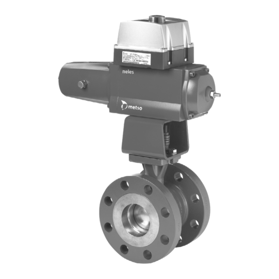
- Page 1 V-port segment valves Series R Installation, Maintenance and Operating Instructions...
-
Page 2: Table Of Contents
3 R 74 en Table of Contents DIMENSIONS AND WEIGHTS ...... 18 11.1 Series RA ..........18 GENERAL............3 11.2 RA - EC ..........19 Scope of the manual ......3 11.3 RA - EJ, EJA ........20 Valve construction........3 11.4 RA-B1C .......... -
Page 3: General
3 R 74 en GENERAL Scope of the manual This manual provides essential information on R series V-port segment valves, i.e. RA, RE and RE1 valves. Actuators and other accessories are only discussed briefly. Refer to the individual manuals for further infor- mation on their installation, operation and mainte- nance.. -
Page 4: Technical Specifications
3 R 74 en Technical specifications Temperature (°F) Face-to-face length: RA: Neles length RE, RE1: acc. to IEC/DIN 534-3-2 Body rating: RA: ASME Class 300 or PN 40 RE, RE1: ASME Class 300 or PN 50/PN 40 Max. pressure differential: see Figs. 5 and 6 Q-R_DN25-80, R_DN25-80 Temperature range: see Fig. -
Page 5: Recycling And Disposal
Foreign particles, such as sand or pieces of noise level depends on the application. It can be welding electrode, will damage the segment sealing measured or calculated using the Metso Nelprof soft- surface and seats. ware. Observe the relevant work environment regula- The valve has an arrow indicating the flow direction. -
Page 6: Actuator
In some cases, for instance when a large-size actuator CAUTION: is used or when the pipeline vibrates heavily, support- Do not dismantle the valve or remove it from the ing the actuator is recommended. Contact Metso’s pipeline while the valve is pressurized! Automation business for further information. - Page 7 3 R 74 en 4.2.1 RA series 4.2.2 RE / RE1 series In gland packing, V-ring set (20), tightness is ensured by In gland packings, tightness is ensured by the contact pressure caused by the wave spring (32). See Fig. 11. between the gland follower and the packing rings.
-
Page 8: Detaching The Actuator
3 R 74 en Removing the valve from the pipeline CAUTION: Do not dismantle the valve or remove it from the pipeline while the valve is pressurized! ❑ Make sure that the pipeline is not pressurized and that it is empty. Also make sure that no medium is led into the pipeline while the valve is being removed or after it has been removed. - Page 9 3 R 74 en ❑ Tap the seat (4) with a soft spindle all around the cir- cumference from the upstream side to make it fall into the body, Fig. 16. sharp edges sharp edges must be must be rounded off rounded off Fig.
-
Page 10: Dismantling The Valve
3 R 74 en ❑ Check that the spring angles extend to the con- trol face. Fig. 25 Securing with a plastic spindle Dismantling the valve Fig. 22 Pushing the the spring angles against the ❑ Turn the valve into the closed position. control face ❑... -
Page 11: Assembly
Moreover, the drive shaft is welded to General the segment in the high-consistency versions. Contact the manufacturer for more information. Different Metso actuators can be mounted using suita- ❑ Install the blind flange (10) with gaskets (19), ble brackets and couplings. The valve can be operated, tighten the bolts (26), see Table 4. - Page 12 3 R 74 en a two-piece cone-shaped bushing, which is tightened DIN keyways at firmly with a tightening screw (I) around the valve shaft. bushing split ❑ Mount the bushing and the tightening screw from the mounting interface side of the actuator, according to Fig.
-
Page 13: Detaching Ec And Ej Actuators
3 R 74 en with the drive shaft in lower position (before the valve is installed). Tighten the nut of the tool in such a way that the tool pulls the drive shaft to the uppermost position. The position may be checked from the side of the tool. -
Page 14: Installing B1J Actuators
3 R 74 en There is no need to adjust the stop screw if the actuator rized and the air supply connection must be open. The is re-installed in the same valve. Drive the actuator pis- valve must be in the open position, see Fig. 10. ton to the housing end (open position).Turn the actuator The rest of the installation procedure is the same as for by hand until the valve is in the open position (unless it... -
Page 15: Malfunctions
3 R 74 en ❑ ❑ The actuator must not be pressurized and the air Adjust the valve open and closed positions by supply connection must be open. means of the screws at the side of the actuator; ❑ Turn the valve segment to correspond to the remember to tighten the locking nuts. -
Page 16: Exploded Views And Parts Lists
3 R 74 en EXPLODED VIEWS AND PARTS LISTS 10.1 Series RA E SEAT 26 10 19 17 4 5 6 1 35 35 T SEAT RA150 - 250 RA025 - 100 16 32 31 20 31 S SEAT 4 5 6 12 14 3 15 Item Qty. -
Page 17: Series Re, Re1
3 R 74 en 10.2 Series RE, RE1 E SEAT 26 10 19 17 4 5 6 35 35 T SEAT RE150 - 400 RE025 - 100 1S SEAT S SEAT 4 5 6 12 14 3 15 Item Qty. Description Spare part category Body... -
Page 18: Dimensions And Weights
3 R 74 en DIMENSIONS AND WEIGHTS 11.1 Series RA øU2 øU1 øS1 øS2 Dimensions of mounting level acc. to ISO 5211 øZ A - A øO Dimensions, mm Type ISO 5211 øB øD øO øS1 øS2 øU1 øU2 øZ 4.76 15.5 133.5... -
Page 19: Ra - Ec
3 R 74 en 11.2 RA - EC MOUNTING POSITION: A-VU (STANDARD) Supply G1/4" VDI/VDE 3845 Dimensions, mm VDI/ Actuator Type mounting øB øD 3845 EC05 / F05 EC07 / F07 G1/4" G1/4" G1/4" G1/4" EC10 / F10 G1/4" G1/4" G1/4"... -
Page 20: Ra - Ej, Eja
3 R 74 en 11.3 RA - EJ, EJA MOUNTING POSITION: A-VU (STANDARD) Supply VDI/VDE 3845 NPT 1/4" Model EJ_A spring to open Dimensions, mm VDI/ Actuator Type mounting øB øD 3845 EJ05 / F05 EJ07 / F07 G1/4" G1/4" G1/4"... -
Page 21: Ra-B1C
3 R 74 en 11.4 RA-B1C I max MOUNTING POSITION A-VU (STANDARD) øD SUPPLY 1/4 NPT SIGNAL M20 X 1.5 CABLE GLAND øB FLOW DIRECTION Dimensions, mm Type Δp øB øD RA_025-B1C6 RA_040-B1C6 RA_050-B1C6 RA_050-B1C9 13,5 RA_065-B1C6 RA_065-B1C9 RA_080-B1C6 RA_080-B1C9 RA_100-B1C6 RA_100-B1C9 RA_150-B1C9... -
Page 22: Ra - B1J, B1Ja
3 R 74 en 11.5 RA - B1J, B1JA I max MOUNTING POSITION A-VU (STANDARD) øD SUPPLY 1/4 NPT SIGNAL M20 X 1.5 CABLE GLAND øB FLOW DIRECTION Dimensions, mm Type Δp øB øD RA_025-B1J8/B1JA8 50/50 RA_040-B1J8/B1JA8 50/50 RA_050-B1J8/B1JA8 50/50 RA_065-B1J8/B1JA8 50/50 RA_080-B1J8/B1JA8... -
Page 23: Ra - M
3 R 74 en 11.6 RA - M øB øD Actuator/ Dimensions, mm Type mounting øD øB øZ ISO 5211 M07/15F05 33/38* M07/15F05 M07/15F05 M07/15F05 M07/20F07 M07/20F07 M10/25F10 M12/30F12 M12/35F12 M14/35F12 *) Actuators equipped with extended input shaft. **) Actuators M07...M12 are equipped with handwheel type SR, actuators M14...M16 are equipped with handwheel type R. -
Page 24: Series Re, Re1
3 R 74 en 11.7 Series RE, RE1 DN 600...700 DN 25...100 DN 150...500 RE_E DN 25...400 RE_A DN 25...700 (SPLINES) (KEY) ØO ØO1 Valve is shown in closed position Dimensions, mm Shaft dimensions, mm DN / inch RE_A (Key) øD S/S2 øO... -
Page 25: Re - Ec
3 R 74 en 11.8 RE - EC MOUNTING POSITION: A-VU (STANDARD) Supply SIGNAL PG 13,5 G1/4" VDI/VDE 3845 Dimensions, mm Max Δp DN / inch Actuator øD 25 / 1" EC05 40 / 1 1/2" EC05 50 / 2" EC05 EC07 65 / 2 1/2"... -
Page 26: Re - Ej, Ej_A
3 R 74 en 11.9 RE - EJ, EJ_A MOUNTING POSITION: A-VU (STANDARD) Model EJ spring to close SIGNAL PG 13,5 Supply G1/4" VDI/VDE 3845 Max Δp DN / inch Actuator Dimensions, mm øD 25 / 1" EJ05 40 / 1 1/2" EJ05 50 / 2"... -
Page 27: 11.10 Re - B1C
3 R 74 en 11.10 RE - B1C MOUNTING POSITION A (STANDARD) øD SUPPLY 1/4 NPT SIGNAL M20 X 1.5 CABLE GLAND øB FLOW DIRECTION Dimensions, mm REJ_ PN 10 REK_ PN 16 REL_ PN 25 REM_ PN 40 REC_ ASME 150 RED_ ASME 300 Δp Type NPS DN... -
Page 28: 11.11 Re - B1J, B1Ja
3 R 74 en 11.11 RE - B1J, B1JA MOUNTING POSITION A (STANDARD) øD SUPPLY 1/4 NPT SIGNAL M20 X 1.5 CABLE GLAND øB FLOW DIRECTION REC_ ASME RED_ ASME Dimensions, mm REJ_ PN10 REK_ PN16 REL_ PN25 REM_ PN40 Δp Type NPS DN... -
Page 29: Re - Qpii
3 R 74 en 11.12 RE - QPX Spring 3/8 NPT open max outside dia of pipe SIGNAL 1/4 NPT SUPPLY 1/4 NPT Spring close FLOW DIRECTION Total weight, kg Max shut-off Max control Max control Dimensions, mm Actuator Δp bar Δp bar Δp bar Valve+actuator+positioner... -
Page 30: Suitability With Different Flanges, Ra And Re1 Valves
3 R 74 en 11.13 Suitability with different flanges, RA and RE1 valves Flange Valve size DN 25 / 01 DN 40 / 01H DN 50 / 02 DN 65 DN 80 / 03 DN 100 /04 DN 150 / 06 DN 200 / 08 DN 250 ASME B16.5 Class 150 ASME B16.5 Class 300 DIN 2545 PN 40... -
Page 31: Type Code
3 R 74 en TYPE CODE 12.1 Series RA V-port segment valve, series RA -CODE FOR VALVE SIZE DN 25 (01") STANDARD CV Without sign Q-TRIM Low noise and anti-cavitation trim NON-STANDARD CV C005- Max. C = 0.5 C015- Max. C = 1.5 C05- Max. -
Page 32: Series Re, Re1
3 R 74 en 12.2 Series RE, RE1 V-port segment valve, series RE and RE1 -CODE BODY MATERIALS Standard V-port (no sign) ASTM A216 gr. WCB / 1-0619 Low noise and anti-cavitation trim (for DN 50 / 2" and ASTM A351 gr. CF8M / 1.4408 bigger) ASTM A351 gr. - Page 33 3 R 74 en...
- Page 34 3 R 74 en...
- Page 35 3 R 74 en...
- Page 36 3 R 74 en Metso Automation Inc. Europe, Levytie 6, P.O. Box 310, 00811 Helsinki, Finland. Tel. +358 20 483 150. Fax +358 20 483 151 North America, 44 Bowditch Drive, P.O. Box 8044, Shrewsbury, MA 01545, USA. Tel. +1 508 852 0200. Fax +1 508 852 8172 Latin America, Av.
Need help?
Do you have a question about the R Series and is the answer not in the manual?
Questions and answers