Table of Contents
Advertisement
Version 4.0 E, 11/2019
Janitza electronics GmbH
Vor dem Polstück 6
35633 Lahnau / Germany
Telefonischer Support: +49 6441 9642-22
E-Mail: info@janitza.com
www.janitza.com
Power Factor Controller
Prophi
12R / 12RS
®
Power Factor Controller
Manual
Prophi12R/ Prophi 12RS
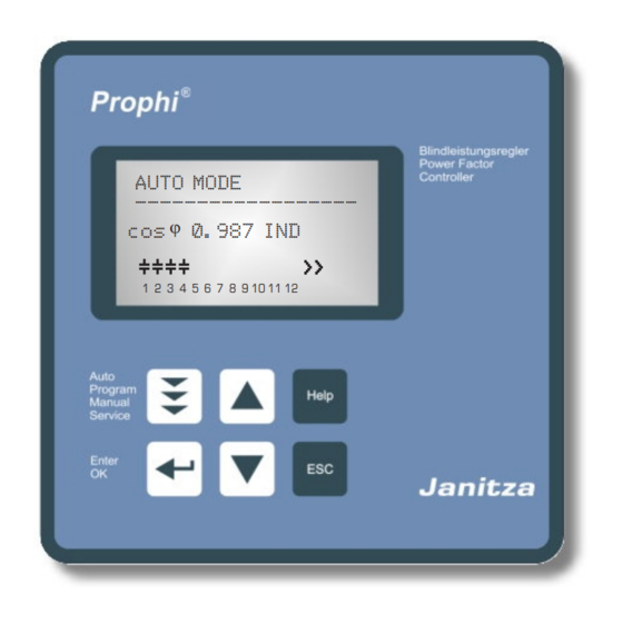
AUTO MODE
------------------
j
cos
0.987 IND
1 2 3 4 5 6 7 8 9 10 11 12
Manual
Version 4.0 - E
SupplyVoltage: 110-440V
Advertisement
Table of Contents

Related Manuals for janitza Prophi 12R


Summary of Contents for janitza Prophi 12R
- Page 1 1 2 3 4 5 6 7 8 9 10 11 12 Manual Version 4.0 - E SupplyVoltage: 110-440V Version 4.0 E, 11/2019 Janitza electronics GmbH Vor dem Polstück 6 35633 Lahnau / Germany Telefonischer Support: +49 6441 9642-22 E-Mail: info@janitza.com...
- Page 2 Prophi 12R / 12 RS ® AUTO MODE AUTO-MODE ------------------ 0.987 IND 1 2 3 4 5 6 7 8 9 10 11 12 DISPLAY-MODE 1 2 3 4 5 6 7 8 9 10 11 12 ------------------ 0.960 ------------------ 19.5 kvar HARMONICS [V] BARGRAPH-MODE...
-
Page 3: Table Of Contents
Prophi 12R / 12 RS ® CONTENTS Section 1 General / type series and accessories Section 2 Installation of the controller / connection diagram Current measurement Programming of phase-correction Error messages: Alarm- / Message relay Section 3 Operating modes Section 4 Automatic operation / display functions Section 5 Programming... -
Page 4: General / Type Series And Accessories
Prophi 12R / 12 RS ® Section1 General The power factor controller Prophi 12 (single phase) enlarges the product range of power factor control devices by a useful combination of the well known features with the advantages of a better visualization. The big graphic display enables a user-friendly programming and gives further benefits such as larger display in the Display-mode and the display of various parameters in bargraph-mode. - Page 5 Prophi 12R / 12 RS ® The controller is supplied as standard for an operating voltage of 110...440 VAC (+-10%), a measuring voltage of 30...440 V~ (L-N) resp. 50...760V~(L-L) and a measuring current of 5A or 1A. A voltage converter is required for different operating voltages. Caution! Voltages which exceed the specified voltage range can damage the device !
-
Page 6: Installation Of The Controller / Connection Diagram
Prophi 12R / 12 RS ® Section 2 Installation and connection of the controller The device is designed to be incorporated into the front panel of a PFC-cabinet. It requires a switchboard section of 138 x 138 mm to DIN 43700/ IEC 61554. The controller is inserted from the front and is attached by means of the appended clamps. -
Page 7: Current Measurement
Prophi 12R / 12 RS ® 2.1 Current measurement When installing the current converter, care should be taken to ensure that the load current and capacitor-current flows through it. The outputs of the compensation network must be installed behind the current converter (in the direction of current flow). If the device is connected up via sum-current converters, the overall conversion ratio is entered. -
Page 8: Operating Modes
Prophi 12R / 12 RS ® 2.3 Error-Messages: Alarmrelay / Message-relay* The PROPHI 12R is equipped with an alarm relay. Version /RS features an additional message relay. The functions may be programmed as follows: Alarm relay: Setting under Message relay: Setting under... -
Page 9: Automatic Operation / Display Functions
Prophi 12R / 12 RS ® Repeated pressing of the "Operating Mode” key takes the user to the various menus: Auto operation Programming Manual operat. Service Expert Mode 1 Expert Mode 2 Display-Editor INTERFACE back to 1 Section 4 Automatic operation - display of network parameter The device is set to automatic operation as standard (not AUTO-INIT). -
Page 10: 5.1. Automatic Initialization
Prophi 12R / 12 RS ® Section 5: Programming Pressing the key once takes the user into the PROGRAMMING mode. The display always shows the parameter and the set value. Values that can be edited are generally put into square brackets [ ]. -
Page 11: Manual Programming
Prophi 12R / 12 RS ® 5.2. Manual programming (program menu) 0 LANGUAGE: This selects the language of the operating menu (German, English, Spanish, Portuguese, French,RU,Cz,NL,PL,TR, IT) 1 I-CONVERTER PRIM: [ 5...13000] A This selects the primary current of the current converter. Adjustment is via the é... - Page 12 Prophi 12R / 12 RS ® 8 MEASURING VOLTAGE [ 30 ... 760]V~ Programming the measuring voltage of the system. The values programmed here always refer to the voltage at the clamps of the device ! The voltage is selected via the é /ê keys. Save and continue with ENTER. 9 V - CONVERTER RATIO [ NO / 230V ...
- Page 13 Prophi 12R / 12 RS ® 13 ALARM TEMP [ 40...85]°C The alarm temperature programmed here is the temperature at which the capacitor stages are disconnected in steps. The controller’s alarm relay responds after ten minutes. (Factory settings) At the same time the display shows the cause of the alarm (over-temperature).
-
Page 14: 5.3 Programming Lock
Prophi 12R / 12 RS ® 15 FAN TEMP * [15...70]°C Input of the switching threshold for the fan. *Only active if option 'Fan' is selected 16 HARMONICS THD-V (harmonic limit) [7] % (OFF or 0.1 - 25.5)% A limit for the total harmonic distortion (in%) can be entered here. When this threshold is exceeded, a message is given. -
Page 15: Manual Operation 1&2 / Programming Of Fixed Stages
Prophi 12R / 12 RS ® Section 6 Manual operation (initial operation, maintenance, service) Programming of fixed stages In manual operation, capacitor branches can be connected/disconnected in the set control series and switching time - irrespective of prevailing power-line conditions. Manual operation 1: The starting condition is STOPP (no stages connected). -
Page 16: Service Menu, Test Run
Prophi 12R / 12 RS ® Section 7 Service menu The service menu is reached by the operating-mode key. The stored maximum values of the network parameters can be displayed here as well as the number of switching operations of the individual capacitors and their operating time. The desired stages [in square brackets] can be selected via the arrow keys. -
Page 17: Expert Mode 1
Prophi 12R / 12 RS ® Section 8.1 Expert mode 1 The expert mode is meant for the adjustment of values which normally should not be changed. As a protection against mal-operation this level has an access code. Factory setting: “6343” The password can be changed in point 22 of expert mode 1. - Page 18 Prophi 12R / 12 RS ® 13 PHASE I [L1] Adjustment of current phase position Selection of phase of current transformer 14 PHASE V [L1-N] Between which conductors has the measuring voltage of the controller been connected:L-L resp. L-N of all phases possible. Phase correction between voltage and current in the measuring system.
-
Page 19: Expert Mode
Prophi 12R / 12 RS ® Section 8.2. Expert mode 2 The additional 2nd expert mode includes all messages for operation, warning and error which are displayed by the PROPHI 12. Here they may be deactivated separately. When deactivated, the indication of the message in the display as well as possible activation of the relay or effects on the control behavior are suppressed. -
Page 20: Control Principle
Prophi 12R / 12 RS ® Section 9 Control principle The control response of the device can be selected in programming mode. The controller has four different control modes: 1. Sequential connection In sequential connection, the required capacitor stages are successively connected and disconnected in stages (last in - first out). -
Page 21: Display Editor
Prophi 12R / 12 RS ® Section 10 Display-Editor The Display-editor is reached by activation the operation button. In the Display-editor a selection of measuring values can be performed which shall be displayed in the Display-mode. Out of the available measuring values shown below 3 values can be selected sequently which then are available in the Display-mode as large letters. - Page 22 Prophi 12R / 12 RS ® Section 13: Menu INTERFACE The PROPHI 12 is optionally equipped with a RS485-interface, an internal clock, a potential free external input (110 … 230 V) and an additional message relay. Therefore the following functions are only available for version /RS: MESSAGE RELAY [1] Functions and settings see section 2.3 Error messages (p.7) 2 FAN TEMPERATURE...
-
Page 23: Interface
Prophi 12R / 12 RS ® Depending on the selected protocol the following settings may be partially deactivated: 11 BAUDRATE COM1 Baudrate 9600...256000 adjustable Parity NONE, ODD, EVEN selectable 12 ADRESS COM1 (1...255) 13 Number MMI (1...9) Number of connected MMI 14 Type of measuring device (MMI6000 / MMI7000 / MMI8003 / UCM-5) 15 Number of BR7000-1 (1...4) -
Page 24: Annex 1 Troubleshouting
Prophi 12R / 12 RS ® Annex 1: Troubleshooting Fault Check / Solution At target cos phi=1 and inductive load, Check terminals of the measuring voltage and switch-off or connection of capacitor in current (l and k)! the corrected line Check phase position Supply / Drawing mismatched Wrong line cos phi is displayed... -
Page 25: Annex 2 Technical Data
Prophi 12R / 12 RS ® Annex 2: Technical data Type series PROPHI 12 Outputs 12 (13) Languages D / E / ES / RU / NL / CZ / PL / F / PT / TR / IT Switching power of relay outputs 250 VAC, 1000 W Number of active outputs Programmable... -
Page 26: Annex 3 Table Of Control Series
Prophi 12R / 12 RS ® Annex 3: Table of control series Control series Loop connection 1 : 1 : 1 : 1 : 1 : 1 : 1 : 1 : 1 : 1 : 1 : 1 Possible 1 : 2 : 2 : 2 : 2 : 2 : 2 : 2 : 2 : 2 : 2 : 2 Possible 1 : 2 : 3 : 3 : 3 : 3 : 3 : 3 : 3 : 3 : 3 : 3... -
Page 27: Annex 4 Default Settings
Prophi 12R / 12 RS ® Annex 4: Default settings Note: The following values for the default settings apply only if the controller is supplied directly from the manufacturer. Otherwise, these values may have been replaced by settings made by the manufacturer of the compensation network (optimal values for the relevant network). - Page 28 Prophi 12R / 12 RS ® Application: Coupling of two PFC-systems using 2 PF-controllers The coupling of two compensation systems via the interface of PF-controllers Prophi12RS offers following advantages: - no sum current transformer and no current transformer switching required - easy installation, real dynamic compensation of both compensation systems Feed 1 Feed 2...
- Page 29 Prophi 12R / 12 RS ® Application: Mixed dynamical compensation system and cascading controllers A mixed dynamical compensation system implements economically the advantages of a dynamic fast network. (Fast changing loads are compensated dynamically and basic loads / slowly changing loads are compensated conventionally) For designing a mixed-dynamical compensation system a special controller is available: The Prophi 12TRS supports up to 12 transistor-outputs (for triggering thyristor modules) and...
- Page 30 Prophi 12R / 12 RS ® Application: Capacitor current monitoring using MMI6000 Application For permanent current monitoring inside the compensation system the MMI6000 is recommended as an accessory for the controller. This measuring device is able to determine the sum current of the complete PFC system as well as the current of single capacitor branches.
-
Page 31: Alarm And Status Notifications
Prophi 12R / 12 RS ® Alarm- and status messages in the display Status indication (s.table) AUTO MODE ------------------ MASTER SLAVE 0.987 IND Message occurs in case of error resp. 1 2 3 4 5 6 7 8 9 10 11 12 relay is active (s.table) Message relay was parameterized with a function (only version /RS) -
Page 32: Handling-Diagram / Short Reference
Prophi 12R / 12 RS ® By pressing the cursor buttons (up / down) the stage display mode can be changed AUTO MODE --------------- PROGRAMMING 1.000 IND AUTO-INIT* 1 2 3 4 5 6 7 8 9 10 11 12 [ NO ] LANGUAGE 1 CURRENT TRANSF. - Page 33 Prophi 12R / 12 RS ® only available if control serie “E” is selected MANUAL MODE SERVICE EXPERT.MODE 1 CONTROL SERIES EDITOR 1 PASSWORD ???? [ 6343 ] MANUAL MODE 1 KVAR-RATIO C1 [ 1 ] 1 min/max VOLTAGE 2 BASIC SETTINGS STOPP C 1.00 IND 2 2 2 2 2 2 2 2 2 2...
- Page 34 Prophi 12R / 12 RS ® version /RS only Back to EXPERT.MODE2 DISPLAY EDITOR INTERFACE START-IMAGE 1 PASSWORD ???? [ 6343 ] 1. DISPLAY [1] MESSAGE RELAY [1] Release [YES] or [RELAYS / ERROR] [ OFF ] blocking [NO] or delay-time of following reports or alarms: FAN TEMPERATURE...
- Page 35 Prophi 12R / 12 RS ®...
- Page 36 Janitza electronics GmbH Vor dem Polstück 6 D-35633 Lahnau Tel.: +49 6441 - 9642-0 E-Mail: info@janitza.de info@janitza.de | www.janitza.de...
Need help?
Do you have a question about the Prophi 12R and is the answer not in the manual?
Questions and answers