Table of Contents
Advertisement
Quick Links
matev GmbH
Nürnberger Str. 50
90579 Langenzenn
T +49 9101 9087 -0
F +49 9101 9087 -20
info@matev.eu
www.matev.eu
Original operating manual
Front Power System FPS-LS J23/27
LS type J 23/27
for
Front Power System FPS-LS J23/27
Front PTO Shaft FPS-LS J23/27
Joystick Kit Dual, article no.
Universal Joint Shaft Guard
Version 05/2015
Advertisement
Chapters
Table of Contents

Related Manuals for matev FPS-LS J23/27


Summary of Contents for matev FPS-LS J23/27
- Page 1 T +49 9101 9087 -0 F +49 9101 9087 -20 info@matev.eu www.matev.eu Original operating manual Front Power System FPS-LS J23/27 LS type J 23/27 Front Power System FPS-LS J23/27 Front PTO Shaft FPS-LS J23/27 Joystick Kit Dual, article no. Universal Joint Shaft Guard...
-
Page 2: Table Of Contents
Contents Table of contents About this operating manual ..................3 Safety ......................... 4 Intended use ....................... 4 Qualifications of personnel ..................5 General safety notices ....................5 Special safety notices ....................5 Installation ......................... 7 Mounting the front power system ................7 3.1.1 Delivery status ...................... -
Page 3: About This Operating Manual
Moreover it is not possible for matev to assume liability for damage that is attributed to improper use or non-intended use of the front power system. -
Page 4: Safety
Safety Safety Guidelines and instructions with which you must comply, are summarized in this section. Personnel who install, operate and maintain the implements, must have read and under- stood this operating manual. Intended use The front power system must only be mounted on tractors, type LS J 23/27, it is used for accommodating small to medium-sized implements, such as snow blades, sweepers, etc. -
Page 5: Qualifications Of Personnel
Safety Qualifications of personnel Only persons 18 years of age or older, or instructed persons should install, operate, and maintain the implements. The operator must have read and understood this operating manual. General safety notices General safety instructions are explained in this section. These safety instructions are used in the subsequent chapters. - Page 6 Safety Attention! Injuries can occur due to improper operation. The implement can be dam- aged. Read the operating manual all the way through. Comply with the safety instructions. Attention! Injuries due to fluid escaping under high pressure. Comply with the notice in the operating manual. ...
-
Page 7: Installation
Installation Installation Danger! Severe injury to the operator or third parties occurs. Switch off the tractor and remove the ignition key before mounting or dis- mounting the implements. Note! Enter the vehicle ID number of the front power system in section 6, page 19 of this operating manual. -
Page 8: Fig. 3: Fastening On The Tractor Frame
Installation Bolt the attachment bracket to the tractor frame on both sides with 2 screws on the front and 4 screws on the rear (see Fig. 3). Threaded unions Fig. 3: Fastening on the tractor frame Then hook the front power system into the bearing bracket and secure it with the arrest bolts shown in the Fig. -
Page 9: Mounting The Front Power System
Installation Mounting the front power system (article no. 131 7237) 3.2.1 Installation of the joystick unit Mount the holder of the joy stick unit, as shown in Fig. 5, on the floor panel, and on the frame of the tractor. Fastening points Fig. -
Page 10: Mounting The Front Hydraulic Extension Kit
Installation 3.2.2 Mounting the front hydraulic extension kit Black (lower the front power system) Green (lift the front power system) Blue (pivot to the right) Red (pivot to the left) Fig. 7: Mounted front hydraulic kit Bolt the hydraulic system console onto the right side of the attachment bracket. To do this, use the two screws M12 x 40 mm already available on the front power sys- tem. -
Page 11: Connection Assignments On The Dual Control Valve
Installation Holder Control device Fig. 9: Attachment position of the control device Holder Bore Fig. 10: Bore position 3.2.4 Connection assignments on the dual control valve A: Feed connection (hydraulic pump) Green/black: Front power system (lifting/lowering) Red/black: Pivoting (left/right) B: Pressureless return (tank) C: Pressure continuation D: Cable pull / joystick connection (pivoting) E: Cable pull / joystick connection with float position (lifting / lowering) -
Page 12: Connecting The Control Device To The Tractor Hydraulic System
Installation Red (pivot to the left) Green (lift) Black (lower) Blue (pivot to the right) Fig. 11: Control device connection assignment Now connect the joystick and the control device to the cable pulls, in accordance with the connection descriptions of the control device in Fig. 11. Then, at a suitable point, fix the hoses in place with cable ties. -
Page 13: Mounting The Front Pto Shaft
Installation Mounting the front PTO shaft (Optionally available, article no. 131 7238) Screw the drive shaft onto the attachment bracket of the front power system from the rear, in accordance with the Fig. below. To do this, use the three provided M8x150 mm screws. -
Page 14: Mounting The Universal Joint Shaft Guard
Installation Mounting the universal joint shaft guard (Optionally available, article no. 131 7239) Fig. 15: Rear universal joint shaft guard holder Fasten the rear universal joint shaft guard holder shown in Fig. 15 below the mid- mount PTO shaft on the tapped bores that are already available. Next, mount the front universal joint shaft guard holder on the drive shaft. -
Page 15: Fig. 17: Front Protective Tube Fastening
Installation Fastening screw M6 Fig. 17: Front protective tube fastening In the rear area the protective tube is fastened via the tension strap. Fig. 18: Tension strap fastening of the protective tube Page 15... -
Page 16: Operation
Operation Operation Attention! Before starting up the implement, read the instructions on safety and han- dling for operation of the entire implement and connection to the tractor. In addition, prior to start-up you must ensure that the vehicle meets the re- quirements specified in the German Road Traffic Vehicle Licensing Act. -
Page 17: Coupling And Uncoupling Implements
Operation Coupling and uncoupling implements Note! Comply with the axle loads specified by the tractor manufacturer. Drive the tractor forward in front of the implement. Lower the front power system hydraulically. Drive slowly toward the implement until the coupling triangle of the tractor is under the coupling triangle of the implement. -
Page 18: Maintenance
Operation Lowering safeguard Fig. 21: Lowering safeguard shown locked Note! Strictly avoid lowering the front power system via the tractor's control lever when the lowering safeguard is locked. Parts of the front power system could be damaged! Maintenance General information Attention! Personal injury or damage to the tractor and the implements can occur. -
Page 19: Maintaining The Hydraulic System
Note! Replace any worn or no longer functioning protective device! Note! Only use original matev spare parts. 5.2.1 Maintaining the hydraulic system Attention! The hydraulic system is under high pressure. Escaping fluids (hydraulic oil) can penetrate the skin and cause severe inju- ... -
Page 20: Disposal
Take the parts to the collection points for residual waste, special waste, or recycle them depending on material. matev GmbH does not provide any disposal services. Guarantee The General Terms & Conditions of matev GmbH provide information on the guarantee conditions. matev GmbH Nürnberger Str. 50... -
Page 22: List Of Illustrations
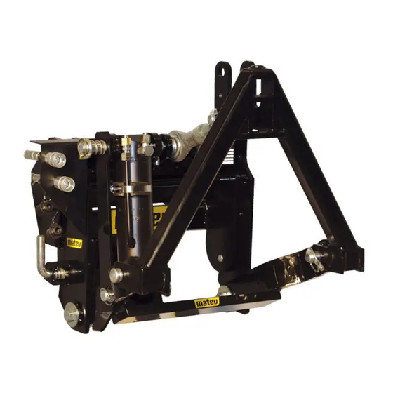
List of illustrations List of illustrations Fig. 1: Lifter unit with hydraulic cylinder ......................7 Fig. 2: Attachment bracket ..........................7 Fig. 3: Fastening on the tractor frame ......................8 Fig. 4: Front power system ..........................8 Fig. 5: Fastening position of the joystick holder ....................9 Fig. -
Page 23: Ec Declaration Of Conformity
Nürnberger Str. 50 90579 Langenzenn declares that the machine Front Power Lifter FPS-LS J23/27 131 7236 complies with the provisions of the Machinery Directive 2006/42/EC and with the implementing national statutory regulations. The signer is authorized to compile the technical documents.
Need help?
Do you have a question about the FPS-LS J23/27 and is the answer not in the manual?
Questions and answers