
Related Manuals for BZB Gear BG-UMV-HA41


Summary of Contents for BZB Gear BG-UMV-HA41
- Page 1 User Manual BG-UMV-HA41 4K 4X1 Seamless Switcher / Multiviewer All Rights Reserved...
-
Page 2: Table Of Contents
Table of Contents 1. Product Introduction ....................1 1.1 Features ......................1 1.2 Package List ....................... 1 2. Specification ........................ 2 3. Panel Description ......................4 3.1 Front Panel ......................4 3.2 Rear Panel ......................5 4. System Connection ..................... 6 5. -
Page 3: Product Introduction
1. Product Introduction The 4K Multi-view switcher is seamless video scaler designed to enable a true 4K display. The switcher features four HDMI inputs and one HDMI output which allows you to display four video sources on one display. It also provides a line input, 1 mix input, 1 SPDIF output and 1 analog output for audio processing. -
Page 4: Specification
2. Specification Video Video Input (4) HDMI IN (1~4) Video Input Connector (4) Type-A female HDMI HDMI Input Resolution Up to 4K@30Hz 4:4:4 Video Output (1) HDMI Video Output Connector (1) Type-A female HDMI HDMI Output Resolution Up to 4K@30Hz RGB HDMI Standard HDMI 1.4 HDCP Version... - Page 5 < 0.05%, 20Hz ~ 20kHz bandwidth, 1kHz sine at 0dBFS level (or max THD+N level) Signal-to-Noise Ratio > 80dB, 20Hz ~ 20kHz bandwidth Crosstalk Isolation < -80dB, 10kHz sine at 0dBFS level (or max level before clipping) L-R Level Deviation <...
-
Page 6: Panel Description
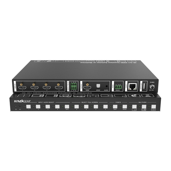
3. Panel Description 3.1 Front Panel ① POWER LED: The LED illuminates green when it is working, and the LED illuminates red when it is standby. ② IR LED: Built-in IR sensor, receive IR signal sent from IR remote. ③ INPUT/AUDIO SELECT: Press 1~4 button to select corresponding HDMI input, its LED illuminates yellow when there is a video signal, it will illuminate blue when the video signal is chosen as input source. -
Page 7: Rear Panel
3.2 Rear Panel ① HDMI IN: Four type-A female HDMI input ports to connect HDMI source devices. ② LINE IN: 3-pin terminal block to connect audio source device like mobile phone or computer to embed in HDMI audio sources. MIX IN: 3-pin terminal block to connect audio source device like mobile phone or computer to mix HDMI audio sources. -
Page 8: System Connection
4. System Connection Cascade Connection:... -
Page 9: Front Panel Control
5. Front Panel Control 5.1 Multi-views Selection Factory default is four quarter views, and factory default input and output corresponding relation is input1 -> window A, input2 -> window B, input3 -> window C, input 4-> window D. Press one of the other two multi-view buttons to change layout. And its multi-view mode and corresponding windows LEDs illuminate blue. -
Page 10: Video Switching Status Inquiry
5.3 Video Switching Status Inquiry In the Multi-view mode (Window A, B, C or D LED illuminate blue). Operation: Windows# Example: Long press Windows B button for more than 3s (Window A, C and D LEDs go out, and then corresponding input source LED will illuminate blue). After 3 seconds, Window A, B, C and D LEDs illuminate blue. -
Page 11: Ir Remote
6. IR Remote ① INPUTS: Press 1-4 button to select the input sources. Press AUTO button to INPUTS automatically detect the input sources. ② SELECT / FULL SCREEN: Press A-D button to display corresponding input as AUTO full-screen mode. ③ CONFIG: Press SWAP button to select window display screen anti-clockwise direction. -
Page 12: Gui Control
7. GUI Control The switcher can be controlled via TCP/IP. The default IP settings are: IP Address: 192.168.0.178 Subnet Mask: 255.255.255.0 Type 192.168.0.178 in the internet browser, it will enter the below log-in webpage: Username: admin Password: admin Type the user name and password, and then click Login to enter the section for video switching. -
Page 13: Multiview Tab
7.1 Multiview Tab Type the default user name and password, and then click Login to enter the Multiview Tab shown as below: Pre-defined ① Pre-defined: Click the corresponding button (Layout1~16) to select video input view and mode. Click the Layout2, Layout5~Layout8, Layout9~Layout12 buttons to enable the Resize function. - Page 14 Click Setting button to enter Window Select, and select any one of input sources and corresponding output shown windows. User-defined ② Click 1, 2, 3, or 4 button to choose User Layout. Select the corresponding input, set the size and position for each window that you want to display on the layout.
-
Page 15: Audio Tab
Click Save button to present the results above selected. Click OK button to exit the current interface and reselect User-defined if the Bandwidth limit exceeded. 7.2 Audio Tab Click On button to enter Mix mode, Click Off button to exit Mix mode. Click Unmute or Mute button to control Audio Output. -
Page 16: Resolution Tab
Select one audio input among input 1-4 and line audio to set as output audio. 7.3 Resolution Tab Click any one of built-in resolutions for the selected input source device, click Auto button to show the resolution from third-party display device automatically. Click Confirm button when the selection is completed. -
Page 17: Cec Tab
ASCII or HEX command format can be selected. Baud Rate: Supports 2400, 4800, 9600, 19200, 38400, 57600 or 115200. Command Ending: NULL, CR, LF or CR+LF can be chosen. Command: Type the command in this box to control the third-party device which is connected to the RS232 port of the switcher. - Page 18 Display ② Click Display buttons to control the third-party display devices. User-defined ③ Select corresponding input source devices and display devices to control via CEC commands.
-
Page 19: Edid Tab
7.6 EDID Tab Upload ① User-defined EDID can be customized by the below steps: Step 1: Prepare the EDID file (.bin) on the control PC. Step 2: Select the EDID file (.bin) according the tooltip. Step 3: Click Apply to upload the user-defined EDID. Setting ②... -
Page 20: Network Tab
Click Setting button to set built-in EDID. Click HDMI 1-4 button to select input source. Click any one of built-in EDIDs for the selected input source device. 7.7 Network Tab Static IP or Dynamic Host Configuration Protocol (DHCP). Modify the static IP Address, Subnet Mask, and Gateway. -
Page 21: Tags Tab
7.8 Tags Tab Modify the input button labels. 7.9 Security Tab Modify the login password. Lock or unlock the front panel buttons. -
Page 22: Gui Update
7.10 GUI Update Web-based GUI for the Seamless Switcher supports online update in http://192.168.0.178:100. First, the Switcher is running. Type the username and password (the same as the GUI log-in settings, modified password will be available only after rebooting) to log in the configuration interface. After that, click Administration at the source Tab to get to Upload Program as shown below: Select the desired update file and press “Apply”, it will start upgrading then. -
Page 23: Rs232 Control
8. RS232 Control Connect the RS232 port to control device (e.g. PC) with RS232 cable. The switcher can be controlled by sending RS232 commands. The below command lists are used to control the switcher. The RS232 control software (e.g. docklight) needs to be installed on the control PC to send RS232 commands. After installing the RS232 control software, please set the parameters of COM number, bound rate, data bit, stop bit and the parity bit correctly, and then you are able to send command in command sending area. -
Page 24: Signal Switching
Command & Feedback Command Description Example @SUBNET_MASK: 255.255.255.0 @GATEWAY: 192.168.0.1 8.2 Signal Switching The ending mark of command is “<CR><LF>”. Command & Feedback Command Description Example Switch an input AV signal to one or #SET_AV 1 more outputs. #SET_AV 1 TO [INPARAM]=1 ~ 4 1 - HDMI 1 #SET_AV [INPARAM] TO... -
Page 25: Audio Switching
8.3 Audio Switching The ending mark of command is “<CR><LF>”. Command & Feedback Command Description Example Mute/Unmute audio. #SET_AUDIO_MUTE 1 #SET_AUDIO_MUTE [PARAM]=0~1. [PARAM] 0 - Disable @AUDIO_MUTE 1 1 - Enable #GET_AUDIO_MUTE Get the audio mute status. @AUDIO_MUTE 1 Set the audio output source. [PARAM]=1 ~ 5 #SET_AUDIO_SRC 1 1 - HDMI 1... -
Page 26: Function Setting
8.4 Function Setting The ending mark of command is “<CR><LF>”. Command & Feedback Command Function Example Set the RS232 baud rate. [PARAM]=1 ~ 7 #SET_RS232_BAUD 0 1 - 115200 2 - 57600 #SET_RS232_BAUD 3 - 38400 [PARAM] 4 - 19200 @RS232_BAUD 5 5 - 9600 6 - 4800... - Page 27 Command & Feedback Command Function Example Set the EDID of HDMI input. [PARAM1]=1 ~ 4 #SET_EDID_MODE 1 1 1 - HDMI 1 2 - HDMI 2 3 - HDMI 3 #SET_EDID_MODE 4 - HDMI 4 [PARAM1] [PARAM2] [PARAM2]=1 ~ 4 1 - 1920x1080 60HZ PCM 2CH @EDID_MODE 1 1 2 - 3840x2160 30HZ PCM 2CH...
- Page 28 Command & Feedback Command Function Example Set multiview mode. [PARAM]=1 ~ 20 1 - 1 WINDOWS Full 2 - 2 WINDOWS PBP 3 - 3 WINDOWS 2U1D #SET_MV_MODE 1 4 - 4 WINDOWS SAME SIZE 5 - 2 WINDOWS PIP LU 6 - 2 WINDOWS PIP LD 7 - 2 WINDOWS PIP RU 8 - 2 WINDOWS PIP RD...
- Page 29 Command & Feedback Command Function Example Enable/Disable whether automatically send corresponding CEC command when detecting Power on/off signal. @SYNCACT_CEC 1 [PARAM]= 0 ~ 1 0 - Disable 1 - Enable #GET_SYNCACT_CEC Get whether automatically send #GET_SYNCACT_CEC corresponding CEC command when @SYNCACT_CEC 1 detecting Power on/off signal.
-
Page 30: Cec Command
Command & Feedback Command Function Example #SET_OFF_DELAY 5 Set the sending interval between two #SET_OFF_DELAY Display OFF commands. [PARAM] @OFF_DELAY 5 [PARAM]=5 ~ 100 (1=100ms) Get the the sending interval between #GET_OFF_DELAY @OFF_DELAY 5 two Display OFF commands. 8.5 CEC Command The ending mark of command is “<CR><LF>”. - Page 31 Command & Feedback Command Function Example Send CEC RIGHT command to source device. #SET_SRC_RIGHT 1 [PARAM]=1 ~ 4 #SET_SRC_RIGHT 1 - HDMI 1 [PARAM] 2 - HDMI 2 @SRC_RIGHT 1 3 - HDMI 3 4 - HDMI 4 Send CEC BACK command to source device.
- Page 32 Command & Feedback Command Function Example 1 - HDMI 1 2 - HDMI 2 @SRC_STOP 1 3 - HDMI 3 4 - HDMI 4 Send CEC PLAY command to source device. #SET_SRC_PLAY 1 [PARAM]=1 ~ 4 #SET_SRC_PLAY 1 - HDMI 1 [PARAM] 2 - HDMI 2 @SRC_PLAY 1...
-
Page 33: Special Command
Command & Feedback Command Function Example Send CEC fast-forward command to source device. #SET_SRC_FF 1 [PARAM]=1 ~ 4 #SET_SRC_FF [PARAM] 1 - HDMI 1 2 - HDMI 2 @SRC_MENU 1 3 - HDMI 3 4 - HDMI 4 Send CEC ON command to display #SET_DIS_ON @DIS_ON device. - Page 34 Command & Feedback Command Description Example Set the HEX command to be sent to display device when power on the switcher. #SET_H_ON_05:30 31 32 [PARAM]= 01~07 33 34 01 - 115200 02 - 57600 #SET_H_ON_[PARAM]:XX 03 - 38400 04 - 19200 05 - 9600 @BAUDRATE: 9600 06 - 4800...
-
Page 35: Firmware Upgrade
9. Firmware Upgrade 1) Prepare the latest upgrade file (.bin) and rename it as “FW_MV bin” on PC. 2) Power off the switcher and connect the FIRMWARE port of switcher to the PC with Type-A USB cable. 3) Power on the switcher and then the PC will automatically detect a U-disk named of “BOOTDISK”. -
Page 36: Warranty
10. Warranty BZBGEAR wants to assure you peace of mind. We're so confident in the quality of our products that along with the manufacturer's one-year limited warranty, we are offering free second-year warranty coverage upon registration*! Taking advantage of this program is simple, just follow the steps below: 1.
Need help?
Do you have a question about the BG-UMV-HA41 and is the answer not in the manual?
Questions and answers