Osburn 1600 Owner's Manual
Inbuilt wood stove
Hide thumbs
Also See for 1600:
- Owner's manual (39 pages) ,
- Installation and operation manual (59 pages) ,
- Installation instructions (5 pages)
Table of Contents
Advertisement
Quick Links
Advertisement
Table of Contents

Related Manuals for Osburn 1600


Summary of Contents for Osburn 1600
- Page 1 OWNER’S MANUAL 1600 MODEL INBUILT Distributed by: My Fireplace Australia PTY Ltd 20 Auto Way Pakenham, Victoria 3810 AUSTRALIA Phone: 03 59 415 008 Fax: 03 59 415 975 Email: info@myfireplaceaustralia.com.au Website: www.myfireplaceaustralia.com.au READ AND KEEP THIS MANUAL FOR REFERENCE...
-
Page 2: Table Of Contents
Keep your sales invoice. We also recommend that you register your warranty online at www.osburn-mfg.com Registering your warranty online will help us track rapidly the information we need on your inbuilt. - Page 3 INTRODUCTION My Fireplace Australia congratulates you on your purchase and wishes to help you get maximum satisfaction from your wood inbuilt. In the pages that follow, we will give you advice on wood heating and controlled combustion as well as technical specifications regarding installation, operation and maintenance of the model you have chosen.
-
Page 4: Technical Specifications
TECHNICAL SPECIFICATIONS Wood Combustible: Maximum heat output – hardwood (Australia): 9.0 kW 69 % Efficiency – hardwood (Australia): 2.4 g/kg Emissions – hardwood (Australia): Metallic black Color : 152 mm Flue Spigot Diameter : Standard Flue system : 4.6 meters Minimum Flue Height: 445 mm Maximum Log Length :... -
Page 5: Installation
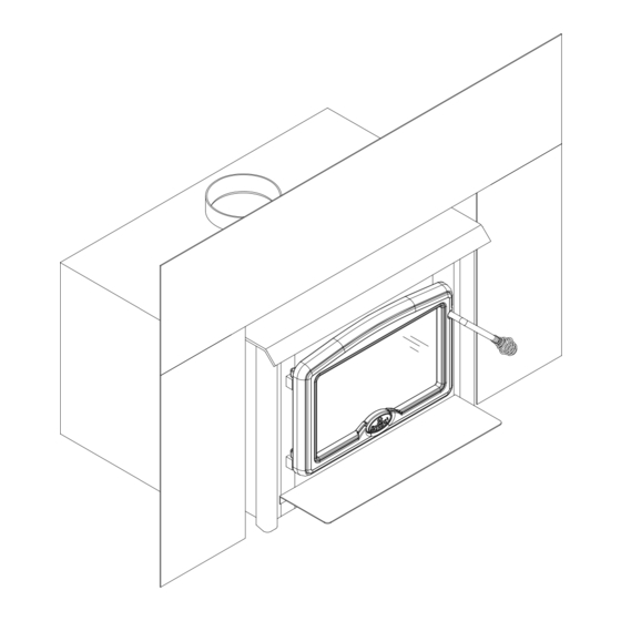
INSTALLATION IT IS RECOMMENDED THAT THE INSTALLATION OF YOUR OSBURN WOOD INBUILT BE CARRIED OUT BY A QUALIFIED SPECIALIST INSTALLER. IF ANY ELECTRICAL WORK IS REQUIRED, IT MUST BE CARRIED OUT BY A LICENSED ELECTRICIAN. WARNING: The instructions pertaining to the installation of your wood inbuilt comply with the AS/NZS 2918 standard. - Page 6 In order to complete the assembly of your Osburn 1600 wood inbuilt, you need to install the door overlay. See figure 1 below for installation instructions : 1- Position the overlay on the door frame and fix it in place from behind using the 4 screws.
-
Page 7: Door Adjustment
DOOR ADJUSTMENT In order for your inbuilt to operate properly, the door should be adjusted periodically to provide an air tight fit. To adjust: • Remove the lock pin (spring pin) by pulling and turning it using pliers ("wise grip") •... - Page 8 1. CONDITION OF THE FIREPLACE AND CHIMNEY: Examine the masonry fireplace and chimney prior to installation, to determine that they are free from cracks, loose mortar, creosote deposits, blockage, or other signs of deterioration. If evidence of deterioration is noted, the fireplace or chimney should be upgraded prior to installation.
-
Page 9: Clearances From Combustibles
CLEARANCES FROM COMBUSTIBLES Adjacent Wall (A) 405 mm Mantle (B) 560 mm From Inbuilt’s Door Opening Top Facing Height (C) 395 mm Side Facing (D) 255 mm Side Floor Protection (E) 200 mm From Inbuilt’s Body Front Floor Protection (F) 455 mm Install only on a non-combustible hearth raised 75 mm above the floor, unless the floor is protected by a listed “Hearth Shield”... -
Page 10: Flue Requirements
FLUE REQUIREMENTS Your wood inbuilt may be hooked to a stainless steel liner or a masonry chimney. It is extremely important that it be installed according to the manufacturer's specifications. If you are using a masonry chimney, it must be lined with fire clay bricks, metal or clay tiles sealed together with fire cement. -
Page 11: Installation Instructions
INSTALLATION INSTRUCTIONS Inspect the masonry fireplace according to the safety information and fireplace requirements and have it cleaned and/or upgraded as necessary. If the installation of the unit renders the existing damper control inaccessible, it will be necessary to either secure the damper wide open or remove it entirely. An inaccessible damper which may fall shut later could cause smoke to enter the room. - Page 12 POSITIONING THE UNIT: The more extended the inbuilt, the greater the heat transfer to the room. When installed as an extended inbuilt, the front edge of the air jacket will be installed flush with the fireplace facing. Otherwise the unit can be moved back as much as 89 mm or any position in between.
- Page 13 Remove the faceplate panels from their box and assemble according to these faceplate instructions: Remove the slide from within the air jacket. Place the faceplate face down on a flat, nonabrasive surface (see Figure 6) so that the sides are a bit towards the middle. Figure 6 Place the slide onto the faceplate so that the bends of the faceplate pieces go inside of the slide.
- Page 14 INSTALLATION ON FACEPLATE: Attach the mitred corners of trim together using the corner brackets. Slide the assembled trim over the edge of the faceplate. See Figures 8 and 9. Attach the left and right sides to the top with corner brackets supplied. Slip the trim over the faceplate and snap the eight faceplate trim clips in place (see Figure 8).
- Page 15 Push the air control (A) in, all the way. Slide the adjustable faceplate sleeve back into its original location until the faceplate fits tightly against the fireplace facing. See Figure 10. One 11mm open end wrench should be used to turn the nut (B), located above the cooktop in the center, up so that it securely fastens the adjustable faceplate sleeve to the top air jacket.
-
Page 16: Operating And Maintenance Instructions
OPERATING AND MAINTENANCE INSTRUCTIONS Keep these instructions for future reference. WARNING: • ANY MODIFICATION OF THE APPLIANCE THAT HAS NOT BEEN APPROVED IN WRITING BY THE AS/NZS 4013. TESTING AUTHORITY IS CONSIDERED AS BREACHING • DO NOT USE FLAMMABLE LIQUIDS OR AEROSOLS TO START OR REKINDLE THE FIRE •... -
Page 17: Testing Your Wood
Many problems related to the operation of a wood inbuilt are caused by the fact that the wood used is too damp or has dried in poor conditions. These problems can be: • problems lighting the fire • creosote build-up causing flue fires •... -
Page 18: Lithing The Fire
Your OSBURN inbuilt may burn differently according to the species of wood used, its moisture content, the size and density of the pieces, the length of the flue, the altitude, and... -
Page 19: Reloading
THE FIREBRICK LINING ON THE FIREBOX THIS WILL ALSO PREVENT OVERFIRING OF YOUR INBUILT • T OSBURN HE INSTALLATION OF A LOG CRADLE IS NOT RECOMMENDED IN YOUR WOOD INBUILT • S HOULD THERE BE A SOOT OR CREOSOTE FIRE IN YOUR FLUE SYSTEM... -
Page 20: Ash Disposal
PREVENTING CREOSOTE BUILD UP • Always burn dry wood. This allows clean burns and higher flue temperatures, therefore less creosote deposit. • Leave the air control full open for about 10 minutes after reloading the inbuilt to bring it back to proper operating temperatures. The secondary combustion can only take place if the firebox is hot enough. -
Page 21: Baffle Installation
BAFFLE INSTALLATION firebrick and ceramic wool baffles must be properly in place for correct burning operation. Have any damaged firebricks replaced. Check the firebricks annually for damage and replace if they are broken or damaged. See figure 12 for the firebrick layout. VERMICULITE BAFFLE TUBE Figure 11 - Baffle installation... -
Page 22: Secondary Air Tube Replacement
SECONDARY AIR TUBE REPLACEMENT Remove cotter pin at left end of tube. Slide tube to right and lower tube end below left plenum. Slide tube to left to remove. Reassemble in reverse order using a new cotter pin. The cotter pin is a hammerlock style and locks into place by hitting the head sharply with a hammer. - Page 23 Manufactured by : STOVE BUILDER INTERNATIONAL INC. 1 www.osburn-mfg.com Distributed by: My Fireplace Australia PTY Ltd...
Need help?
Do you have a question about the 1600 and is the answer not in the manual?
Questions and answers