
Related Manuals for Honeywell Gamewell-FCI NGA


Summary of Contents for Honeywell Gamewell-FCI NGA
- Page 1 Network Graphic Annunciator (NGA) Operations Guide Document 9020-0675 03/21/13 P/N 9020-0675:B1 ECN: 12-0250...
- Page 2 Fire Alarm & Emergency Communication System Limitations While a life safety system may lower insurance rates, it is not a substitute for life and property insurance! An automatic fire alarm system—typically made up of of detector is necessarily best and a given type of detector smoke detectors, heat detectors, manual pull stations, audible may not provide adequate warning of a fire.
- Page 3 Gamewell® and SmartScan® are registered trademarks of Honeywell International Inc. Echelon® is a registered trademark and LonWorks™ is a trademark of Echelon Corporation. ARCNET® is a registered trademark of Datapoint Corporation. Microsoft® and Windows® are registered trademarks of the Microsoft Corporation.
- Page 4 • Your suggestion for how to correct/improve documentation Send email messages to: FireSystems.TechPubs@honeywell.com Please note this email address is for documentation feedback only. If you have any technical issues, please contact Technical Services. Network Graphic Annunciator (NGA) Operations Guide P/N 9020-0675:B1 03/21/13...
-
Page 5: Table Of Contents
Table of Contents Table of Contents Section 1: Introduction......................7 Section 2: The LCD Touch Screen ..................8 2.1: Menu Bar ...............................8 2.2: The Display..............................9 2.3: NGA Touch Screen Tabs and Buttons ......................10 2.3.1: Mass Notification Display Screens....................12 2.4: User-Defined "CAM Text" Messages......................13 2.5: User Defined Text Message Options ......................14 Section 3: LEDs and Audible Sounder ................. - Page 6 Table of Contents 10.3: View Screen (Global Tab)..........................36 10.4: View Screen (Global Tab) Options ......................36 10.5: View Screen (Devices Tab)........................37 10.6: View Screen (Devices Tab) Options ......................38 Section 11: Log Screen ......................39 11.1: Log Screen (Entry Tab) ..........................39 11.2: Log Screen (Entry Tab) Options ........................39 11.3: Access Failed Events Screen........................40 11.4: Access Failed Events Screen Options ......................40 Section 12: Service Screen....................
-
Page 7: Section 1: Introduction
These functions may be performed only by authorized personnel. NOTE: The screen images shown throughout this document are simulated. Actual NGA displays may vary slightly. ® ® E3 Series and NetSOLO are registered trademarks of Honeywell International Inc. Network Graphic Annunciator (NGA) Operations Guide P/N 9020-0675:B1 03/21/13... -
Page 8: Section 2: The Lcd Touch Screen
Section 2: The LCD Touch Screen The LCD Touch Screen is the primary interface with the NGA. It displays messages that identify the sources of alarms, off-normal indications and trouble conditions as these messages occur within the system. The LCD Touch screen also provides access to other NGA functions as described in this document. -
Page 9: The Display
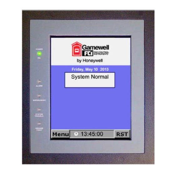
The Display The LCD Touch Screen 2.2 The Display The NGA LCD Graphic Annunciator is a software programmable touch screen interface used for the Gamewell-FCI Emergency Voice Evacuation Systems. It displays text messages of system events, together with system status indicating LEDs, and touch screen switches for the following conditions: •... -
Page 10: Nga Touch Screen Tabs And Buttons
The LCD Touch Screen NGA Touch Screen Tabs and Buttons 2.3 NGA Touch Screen Tabs and Buttons The NGA LCD Graphic Annunciator is a software programmable touch screen interface used to control the E3 Series Voice Evacuation System. The touch screen tabs and buttons are software programmable and are used to control the combined in-building Fire/Mass Notification System. - Page 11 NGA Touch Screen Tabs and Buttons The LCD Touch Screen Event Description Activation Mass Notification Touch Screen Tabs Text Message Displays user-defined If this tab is activated, the tab messages. The tab background color (light green) background color is light appears on the Display Screen LS10013-A1Fig5.2.2.1.10 green.
-
Page 12: 1: Mass Notification Display Screens
The LCD Touch Screen NGA Touch Screen Tabs and Buttons 2.3.1 Mass Notification Display Screens Figure 2.3.1.1 shows the Display screen with the ACU-In-Control and Figure 2.3.1.2 shows the Display screen with the LOC-In-Control. Figure 2.3.1.1 ACU-In-Control Figure 2.3.1.2 LOC-In-Control Network Graphic Annunciator (NGA) Operations Guide P/N 9020-0675:B1 03/21/13... -
Page 13: User-Defined "Cam Text" Messages
User-Defined "CAM Text" Messages The LCD Touch Screen 2.4 User-Defined "CAM Text" Messages The NGA supports up to 512 User-Defined CAM Text Messages that may be triggered according to user programming.When one of these text messages are active, the "FIRE or MNS MSG" tab appears active on the "System Status"... -
Page 14: User Defined Text Message Options
The LCD Touch Screen User Defined Text Message Options 2.5 User Defined Text Message Options Table 2.5.1 describes the tabs and buttons that appear on the User-Defined Text Message tab screen. The following options are available when User-Defined Text Messages are displayed. System Event Button Description UP / DOWN... -
Page 15: Section 3: Leds And Audible Sounder
Section 3: LEDs and Audible Sounder The NGA has the following five (5), front-panel LEDs and an audible sounder to provide visual and audible indications of alarm, off-normal and trouble conditions. • Power on • Alarm • Supervisory • System Trouble • Ground Fault The LEDs and audible sounder operation are described in the following sections: 3.1 Power On LED... - Page 16 LEDs and Audible Sounder CO/Gas Alarm Operation 3.3.1.1 CO Alarm Persistent Text Indicators While the system displays the current event, Table 3.3.1.1.1 lists the following text indicators that how the following types of events that occurred. Indicator Event CO ALARM Indicates that a CO Alarm occurred in the region to which the NGA belongs.
-
Page 17: Mass Notification (Mns) Alarm Operation
Mass Notification (MNS) Alarm Operation LEDs and Audible Sounder 3.4 Mass Notification (MNS) Alarm Operation Figure 3.4.1 illustrates the NGA Display Panel with the MNS Alarm activated. If the MNS Alarm is the highest priority event, the following occurs: The Main window displays the following: •... -
Page 18: Supervisory Led
LEDs and Audible Sounder Supervisory LED 3.5 Supervisory LED The "SUPERVISORY" LED blinks on/off and the sounder sounds on an on/off pattern when the system is in a Supervisory Off-normal or MNS Supervisory condition. Again, the "ACK" button that appears will acknowledge the off-normal condition that is currently being displayed. After all Supervisory Off-normal and MNS Supervisory conditions are acknowledged, the "ACK"... -
Page 19: Section 4: The Main Menu
Section 4: The Main Menu To open the NGA's Main Menu, press the Menu button on the bottom of the screen. The following selections appear on the Main Menu: • Configure • • Walk/Drill • Service • • Clock • View •... -
Page 20: Reset Option
The Main Menu Reset Option 4.2 Reset Option Use the RST (Reset) button in the lower-right corner of the screen to reset the system. By default, the NGA will send a Reset Command to all nodes that are within its region. To configure the NGA to reset all nodes in the system, the user can change the "Global Reset"... - Page 21 NOTE: FIRE AND MNS RESET BUTTONS OPERATION: The Fire and MNS Reset buttons operate independently of each other. When both Fire and MNS Alarm conditions exist, the highest priority condition must be reset first followed by the lower priority condition. - For FIRE overrides MNS, the Fire Alarm condition must be reset first.
-
Page 22: 2: Acknowledge Alarm Events
The Main Menu Reset Option 4.2.2 Acknowledge Alarm Events To activate the Acknowledge Alarm, do the following: Enter the required Password (if prompted) to “Unlock” and access the system controls. Press the ACK (Acknowledge) button to silence the audible sounder. The flashing red Alarm indicating LED will light steady, after you acknowledge all alarm conditions. -
Page 23: Section 5: Passwords
Section 5: Passwords The options accessible through the NGA's Main Menu are password protected. To access the various option displays, enter a six-digit password. The factory default passwords are listed in Table 5.1: Level 1= 111111 Level 2= 222222 Level 3= 333333 Level 4= 444444 Table 5.1 Default Passwords 5.1 Factory Default Passwords... -
Page 24: Numeric Entry Keypad Screen
Passwords Numeric Entry Keypad Screen 5.3 Numeric Entry Keypad Screen Once a Menu option is chosen, the NGA will display a Numeric Entry Keypad. Use this screen to enter the password. The NGA will also indicate which access level (1-4) is required. Enter only the password indicated. -
Page 25: Section 6: Configure Screen
Section 6: Configure Screen The Configure screen provides access to the Auto-configure options available on the following nodes: ILI-E3 Series ILI95-E3 Series • ILI-MB-E3 • ILI95-MB-E3 (Intelligent Loop Interface-Main Board) (Intelligent Loop Interface 95- Main Board) • ILI95-S-E3 LI-S-E3 ... -
Page 26: Section 7: Walk/Drill Screen
Section 7: Walk/Drill Screen The Walk/Drill screen allows activation and deactivation of the system's Audible and Silent Walk Test functions as well as the system's Fire Drill mode. The following tabs appear on the Walk/Drill screen: • Region • Drill •... -
Page 27: Walk/Drill Screen (Fire Drill Tab)
Walk/Drill Screen (Fire Drill Tab) Walk/Drill Screen 7.3 Walk/Drill Screen (Fire Drill Tab) The screen that appears on the Fire Drill tab is similar to the Main Walk/Drill screen. Table 7.3.1 describes the buttons that appear on the Fire Drill screen. Fire Drill Description Buttons... -
Page 28: Walk/Drill Screen (Silent Walk Test Tab)
Walk/Drill Screen Walk/Drill Screen (Silent Walk Test Tab) 7.5 Walk/Drill Screen (Silent Walk Test Tab) The screen that appears on the Silent Walk Test tab is similar to the Main Walk/Drill screen. Table 7.5.1 describes the buttons that appear on the Silent Walk Test screen. Walk/Drill Description Screen Buttons... -
Page 29: Section 8: I/O Screen
Section 8: I/O Screen The I/O screen allows the user to enable or disable sensors or modules connected to any ILI-MB-E3, ILI-S-E3, ILI95-MB-E3 and ILI95-S-E3 on the network. In addition, any output module connected to an ILI-MB-E3, ILI-S-E3, ILI95-MB-E3 and ILI95-S-E3 may be manually activated or returned to its normal automatic operation. -
Page 30: I/O Screen (Output Tab)
I/O Screen I/O Screen (Output Tab) 8.3 I/O Screen (Output Tab) The Output Tab of the I/O screen allows the user to manually activate output devices and return the output devices to their normal automatic operation. After the Output Tab is activated, an SLC device address must be selected. There are two methods of selecting the device address. -
Page 31: I/O Screen (Device Tab)
I/O Screen (Device Tab) I/O Screen 8.5 I/O Screen (Device Tab) The Device tab of the I/O screen allows the user to manually enable or disable SLC devices. After you activate the Device tab, an SLC device address or a discrete device (NAC circuit) must be selected. -
Page 32: I/O Screen (Device Tab) Options
I/O Screen I/O Screen (Device Tab) Options 8.6 I/O Screen (Device Tab) Options Table 8.6.1 describes the options that appear on the I/O, Device tab screen. I/O Screen (Device Tab) Description Controls LOOP Tap LOOP to enable a direct entry of a loop number (loop 1, loop 2 or discrete devices). -
Page 33: Section 9: Clock Screen
Section 9: Clock Screen Each node in the system maintains a 24-hour real-time clock. The time and date may be set via the NGA. The following list the two ways to open the Clock screen. • Select the Clock item that appears in the NGA's Main Menu. •... -
Page 34: Clock Screen Options
Clock Screen Clock Screen Options 9.2 Clock Screen Options Table 9.2.1 describes the buttons that appear on the Clock screen. Clock Screen Description Buttons <- Bkspc Press this button to move the cursor one space to the left to allow the correction of an entry. -
Page 35: Section 10: View Screen
Section 10: View Screen The View screen allows the user to view configuration information for any ILI-E3 or ILI95-E3 Series node that is present in the system. The following tabs appear on the View screen: • Node • Devices • Global The types of information that may be viewed include the following settings: •... -
Page 36: View Screen (Global Tab)
View Screen View Screen (Global Tab) 10.3 View Screen (Global Tab) The Global tab of the View screen allows the display of the general settings of any ILI-E3/ILI95-E3 Series on the network. Figure 10.3.1 illustrates the screen that appears when the user selects the Global tab from the View screen. -
Page 37: View Screen (Devices Tab)
View Screen (Devices Tab) View Screen 10.5 View Screen (Devices Tab) View Screen Description (Global Tab) Options I/O Devices Displays PAS Night Bypass and the Multilevel Alert and Action percentages. NACs Displays the NAC delay settings (such as the NAC Cutoff Delay and the Silence Inhibit Delay). -
Page 38: View Screen (Devices Tab) Options
View Screen View Screen (Devices Tab) Options 10.6 View Screen (Devices Tab) Options Table 10.6.1 describes the controls that appear on the View, Devices Tab screen. The following types of information may be displayed for each SLC device: • Device Type •... -
Page 39: Section 11: Log Screen
Section 11: Log Screen 11.1 Log Screen (Entry Tab) The Log screen allows you to view events that are stored in the NGA's History Log. In addition, the Log screen provides options for printing and clearing the History Log. Figure 11.1.1 illustrates the screen that appears when the user selects the Entry tab from the Log screen. -
Page 40: Access Failed Events Screen
Log Screen Access Failed Events Screen 11.3 Access Failed Events Screen The Access Failed Events screen allows you to view Access Failed Events that are stored in the NGA's History Log. Figure 11.3.1 illustrates the Close button and Figure 11.3.2 illustrates Continue button on the Access Failed Events screen. -
Page 41: Section 12: Service Screen
Section 12: Service Screen The Service screen provides options that change the NGA's settings. It consists of the following five tabs: • • • Version • Logo • Query NOTE: These settings only apply to the local NGA and not to other NGAs in the system. Some of these settings may be overwritten by a configuration download from the CAMWorks programming software. -
Page 42: Service Screen (Nga Tab - Page 1) Options
Service Screen Service Screen (NGA Tab - Page 1) Options 12.2 Service Screen (NGA Tab - Page 1) Options On the NGA tab screen, the blue text that appears functions as hyperlinks. The links function in two different ways: • The following settings are simple ON/OFF selections: –... -
Page 43: Service Screen (Nga Tab - Page 2) Options
Service Screen (NGA Tab - Page 2) Options Service Screen 12.3 Service Screen (NGA Tab - Page 2) Options The second page of the NGA tab contains blue hyperlinks that control the following option: • The following setting is a simple ON/OFF selection: –... -
Page 44: Service Screen (Lcd Tab)
Service Screen Service Screen (LCD Tab) 12.4 Service Screen (LCD Tab) The LCD tab that appears on the Service screen includes controls for changing two settings that affect the NGA's LCD display. These settings are brightness and contrast. Figure 12.4.1 illustrates the screen that appears when the user selects the LCD tab from the Service screen. -
Page 45: Service Screen (Version Tab)
Service Screen (Version Tab) Service Screen 12.5 Service Screen (Version Tab) The Version tab displays the Version number of the System Operating Software (SOS) or firmware that is currently installed in the NGA. The software version may be changed via flash download ®... -
Page 46: Service Screen (Logo Tab)
Service Screen Service Screen (Logo Tab) 12.6 Service Screen (Logo Tab) The NGA supports the display of a user-supplied Logo image that may be displayed when the system is in normal condition. If a user-supplied Logo has already been downloaded, Figure 12.6.1 illustrates the screen that may appear when the user selects the Service Screen (Logo Tab). -
Page 47: Service Screen (Query Tab)
Service Screen (Query Tab) Service Screen 12.8 Service Screen (Query Tab) The Service Screen (Query Tab) allows the user to perform a network query process. This network query indicates which network nodes are present and in communication with the NGA. The Query process displays additional information from each node that responds to the Query. -
Page 48: Service Screen-Query Report And Node Types
Service Screen Service Screen-Query Report and Node Types 12.10 Service Screen-Query Report and Node Types The Query Report includes the following fields described in Table 12.10.1. Fields Description Node Numbers Numbers of the nodes to which the NGA communicates. Note Type The node type of the node. -
Page 49: Index
Index Silence 11 Up/Down Arrows 11 Clock Screen 33 NGA Touch Screen Tabs CO Alarm Fire Alarm 10 Persistent Text Indicators 16 Fire Alarm Event 10 CO/Gas Alarm 15 Fire Supervisory 10 Configure Screen 25 Fire Trouble 10 Node tab 25 Mass Notification Alarm 10 Mass Notification Event 10 Mass Notification Supervisory 10... - Page 50 W–W Index Audible Walk Test Tab 27 Fire Drill Tab 27 Region Tab 26 Silent Walk Test Tab 28 Network Graphic Annunciator (NGA) Operations Guide P/N 9020-0675:B1 03/21/13...
- Page 51 Manufacturer Warranties and Limitation of Liability Manufacturer Warranties. Subject to the limitations set forth herein, Manufacturer warrants that the Products manufactured by it in its Northford, Connecticut facility and sold by it to its authorized Distributors shall be free, under normal use and service, from defects in material and workmanship for a period of thirty six months (36) months from the date of manufacture (effective Jan.
- Page 52 Gamewell-FCI 12 Clintonville Road Northford, CT 06472-1610 USA 203-484-7161 fax 203-484-7118 www.gamewell-fci.com...
Need help?
Do you have a question about the Gamewell-FCI NGA and is the answer not in the manual?
Questions and answers