Honeywell Excel 50 User Manual
Hide thumbs
Also See for Excel 50:
- Installation instructions manual (40 pages) ,
- User manual (64 pages)

Related Manuals for Honeywell Excel 50


Summary of Contents for Honeywell Excel 50
-
Page 1: User Guide
Excel 50 USER GUIDE Copyright © 2016 Honeywell Inc. • All Rights Reserved EN2B-0222GE51 R0216... -
Page 2: Trademark Information
EXCEL 50 MMI - USER GUIDE Trademark Information Echelon, LON, L , LonBuilder, NodeBuilder, LonManager, ORKS LonTalk, LonUsers, LonPoint, Neuron, 3120, 3150, the Echelon logo, the logo, and the LonUsers logo are trademarks of Echelon Corporation registered in the United States and other countries. LonLink, LonResponse, LonSupport, and LonMaker are trademarks of Echelon Corporation. -
Page 3: Table Of Contents
EXCEL 50 MMI - USER GUIDE CONTENTS User Guide ......................i About This User Guide ..................vii Operator's Terminal ..................... 1 Keyboard ......................1 Basic Function Keys ....................2 Resetting ......................3 Fast-Access Keys ......................4 ... - Page 4 EXCEL 50 MMI - USER GUIDE Points in Trend......................28 Trend Buffer ....................... 29 Hours Run ......................... 29 DDC Parameters ....................... 30 System Configuration ..................31 System Info ........................ 31 System Time ......................32 ...
- Page 5 EXCEL 50 MMI - USER GUIDE Individual Data-Point Attributes ..............61 Data-Point Name ....................... 61 Appending the Controller's Number to the Data-Points' Names ......61 The 'Operating Mode' Attribute .................. 61 Optimizing a Switch-Point ..................62 ...
-
Page 7: About This User Guide
EXCEL 50 MMI - USER GUIDE ABOUT THIS USER GUIDE This User Guide describes operation of the Excel 50 MMI for configurable applications with Version 2.05 (or higher) firmware. It focuses on changes in operation with respect to Version 2.04. - Page 8 EXCEL 50 MMI - USER GUIDE EN2B-0222GE51 R0216 viii...
-
Page 9: Operator's Terminal
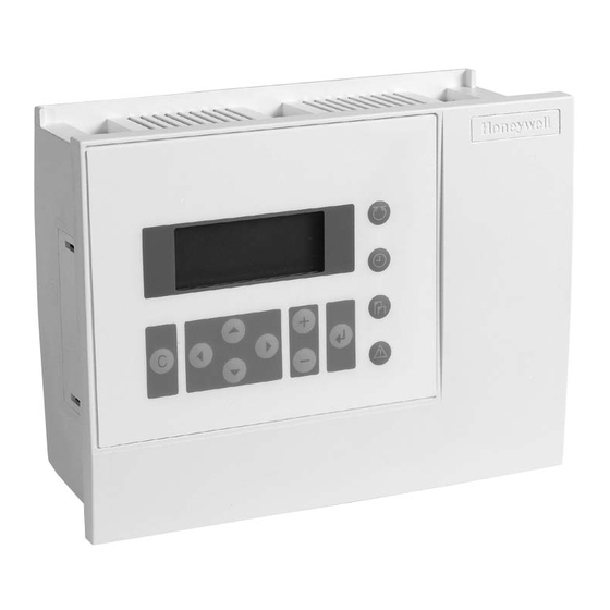
EXCEL 50 MMI - USER GUIDE OPERATOR'S TERMINAL Fig. 1. Excel 50 Man-Machine Interface The Excel 50 controller's MMI (Man-Machine Interface, see Fig. 1) consists of a keyboard and a display described below. Keyboard The keyboard has 8 basic function keys and 4 fast-access keys described below. -
Page 10: Basic Function Keys
EXCEL 50 MMI - USER GUIDE Basic Function Keys The effects of pressing the basic function keys are summarized below. CANCEL: Enables you to escape to the root screen, to cancel an incorrect entry, or to confirm an alarm message. -
Page 11: Resetting
All RAM data and all configuration codes are lost, and the controller will therefore have to be re-initialized (see "Powering Up / Resetting the Controller" on page 47) in order to work with it. You should reset your Excel 50 MMI only as a preliminary to downloading a new application. &... -
Page 12: Fast-Access Keys
EXCEL 50 MMI - USER GUIDE Fast-Access Keys The use of the fast-access keys is summarized below. PLANTS: Displays a list of the selected plant components and their current states. TIME PROGRAMS: Displays a list of configured time programs and provides all time schedule customization options. -
Page 13: Initialization And Entry
Fig. 3. Initialization and entry sequences Initialization Sequence Upon downloading an application into your Excel 50 MMI (see also "Powering Up / Resetting the Controller" on page 47), the initialization sequence will begin. This initialization sequence consists of a series of four screens (see Fig. 3). If the configuration codes are correct, the initialization sequence should be immediately followed by the entry sequence (see section "Entry Sequence"... -
Page 14: Access Levels
EXCEL 50 MMI - USER GUIDE NOTE: The two-digit CPU field (in the upper right-hand corner), the date, and the time will be editable only if you are already in access level 3 (see section "Access Levels" on page 6). -
Page 15: Modifying The Password
EXCEL 50 MMI - USER GUIDE Fig. 5. Entering a password NOTE: The "Change" field will appear only if you are already in access level 3. To enter a password, proceed as follows: 1. Move the cursor to the "****" field. -
Page 16: The Plants Fast-Access Key
EXCEL 50 MMI - USER GUIDE THE PLANTS FAST-ACCESS KEY Fig. 7. The PLANTS fast-access key Plant Components (Data-Point Groups) Pressing the PLANTS fast-access key will cause a listbox headed "Plant Components" to appear (see Fig. 8). Fig. 8. Listbox of plant components (data-point groups) Depending upon your given application (see Table 3 on page 9) and configuration data, this listbox will contain a varying number of items (i.e. -
Page 17: Data-Points
EXCEL 50 MMI - USER GUIDE Table 3. Items appearing in the "Plant Components" listbox Application AH03 HT02 HE01 Sensors Sensors Sensors AHU_Strategy Htg_Strategy Heat Exchg.1 Dampers Boiler1 System Energy Recovery Boiler2 Heating Circ.1 Filters Boiler3 Heat Exchg.2 Heating Boiler4 Heating Circ.2... -
Page 18: Data-Point Attributes
EXCEL 50 MMI - USER GUIDE NOTE: In the case of listboxes spread out over three or more screens, use of the scrollbar (the value of which is incremented or decremented with the PLUS and MINUS keys; see also Table 1 on page 3) can greatly simplify navigation by allowing the user to skip ahead to the screen of interest. -
Page 19: The Time Programs Fast-Access Key
EXCEL 50 MMI - USER GUIDE THE TIME PROGRAMS FAST-ACCESS KEY Fig. 11. The TIME PROGRAMS fast-access key Time Programs Using the TIME PROGRAMS key, you can assign values (e.g. temperatures) and states (e.g. "ON" or "OFF") to data-points belonging to a specific time schedule. -
Page 20: Time Schedules
EXCEL 50 MMI - USER GUIDE Pressing the TIME PROGRAMS fast-access key will cause a listbox with a corresponding heading to appear (see Fig. 12). Fig. 12. Time programs Depending upon your given application (see Table 4) and configuration data, this listbox will contain a varying number of items (i.e. -
Page 21: The "Today" Time Schedule
EXCEL 50 MMI - USER GUIDE Fig. 13. Time schedules belonging to a time program Regardless of your application and configuration, this listbox will always contain the same four items (i.e. time schedules) from which to choose, meaning that you will have to scroll downwards to display the fourth item ("Annual"). - Page 22 EXCEL 50 MMI - USER GUIDE Selecting the "Today" time schedule will cause a listbox with a corresponding heading (containing the given time program and, next to it, the time schedule) to appear (see Fig. 14). Fig. 14. Data-points belonging to the "Today" time schedule...
-
Page 23: The 'Daily' Time Schedule
EXCEL 50 MMI - USER GUIDE Fig. 15. Displaying/configuring the switch-points and state in the "Today" time schedule Fig. 16. Displaying/configuring the switch-points and value in the "Today" time schedule NOTE: After you have changed a data-point's state, value, and/or switch- point(s), it will be marked with an asterisk as shown in Fig. - Page 24 EXCEL 50 MMI - USER GUIDE daycycles) from which to choose. However, you can create as many additional daycycles as you wish (see section "Deleting and Copying/Creating Daycycles" on page 17). The three default daycycles are as follows: "Workday", ...
-
Page 25: Deleting And Copying/Creating Daycycles
EXCEL 50 MMI - USER GUIDE value (in the case of HG1_tsp, a temperature; see Fig. 20 on page 17), its corresponding switch-point ("Time:"), and/or to optimize it ("ON" or "OFF"). Fig. 19. Displaying/configuring the time, state, and optimization of a data- point in the "Daily"... -
Page 26: Deleting A Switch-Point
EXCEL 50 MMI - USER GUIDE Fig. 21. Deleting a daycycle New daycycles are created by copying and modifying existent daycycles. To copy and modify an existent daycycle, go to Fig. 17 (see page 15), move the cursor to the daycycle to be copied (e.g. DP_1), press the PLUS key, and confirm the query appearing in the resultant screen (see Fig. -
Page 27: Creating A Switch-Point
EXCEL 50 MMI - USER GUIDE Fig. 23. Deleting a switch-point Creating a Switch-Point Switch-points are defined by selecting desired data-points from a list of all possible data-points valid for the given daycycle and then editing the corresponding value/state and clock-times (i.e. switch-points). - Page 28 EXCEL 50 MMI - USER GUIDE Fig. 25. Parameters belonging to the "Weekly" time schedule Regardless of your application and configuration as well as the specific time program you have chosen, this listbox will always contain the same seven items (i.e.
-
Page 29: The 'Annual' Time Schedule
EXCEL 50 MMI - USER GUIDE Fig. 27. Confirming assignment of a daycycle to days of the week Upon confirming your selection, you will be returned to the previous screen so that you may continue assigning daycycles to the other days of the week. - Page 30 EXCEL 50 MMI - USER GUIDE Fig. 28. Parameters belonging to the "Annual" time schedule Regardless of your application and the specific time program you have chosen, this screen will always contain two lines ("From:" and "To:") in which you can enter the initial day and final day of the period of time to which a particular daycycle should be assigned.
-
Page 31: Creating Additional Annual Time Schedules
EXCEL 50 MMI - USER GUIDE Fig. 30. Successful completion of the daycycle assignment process This procedure (Fig. 28 to Fig. 30) may now be repeated as often as desired in order to assign individual daycycles to additional periods of time throughout the year. -
Page 32: The System Topics Fast-Access Key
EXCEL 50 MMI - USER GUIDE THE SYSTEM TOPICS FAST-ACCESS KEY Fig. 31. The SYSTEM TOPICS fast-access key EN2B-0222GE51 R0216... -
Page 33: Types Of Data-Points
Regardless of your application or configuration, this listbox will always contain the same three items from which to choose. Types of Data-Points With the Excel 50 MMI, it is possible to obtain information on a total of three different basic groups of data-points: physical data-points (consisting of five different types);... -
Page 34: Types Of Remote Data-Points
EXCEL 50 MMI - USER GUIDE pseudo digital (e.g. internally calculated commands, e.g. point alarms, pump exercise, etc.). Types of Remote Data-Points Remote data-points include the following: remote analog (e.g. outside air temperature, heat demand, etc.) and remote digital (e.g. alarm reset, alarm outputs, etc.). - Page 35 EXCEL 50 MMI - USER GUIDE downwards through several screens in order to display all of the items. In the example considered here, however, there is only one such data-point. Using the basic function keys, you can now move to and select a particular data- point.
-
Page 36: Points In Trend
EXCEL 50 MMI - USER GUIDE key. On the other hand, Fig. 36 would appear if the given data-point was initially in the automatic operation mode; if desired, you could then shift to manual operation by moving the cursor to the corresponding field ("Manual") and pressing the ENTER key. -
Page 37: Trend Buffer
EXCEL 50 MMI - USER GUIDE Disable trend logging for this data-point by moving the cursor to the appropriate field and confirming. Enable trend logging for any desired data-point as follows: 1. Press the PLANT fast-access key. 2. Select the desired item in the "Plant Components" list. -
Page 38: Ddc Parameters
EXCEL 50 MMI - USER GUIDE Fig. 40. Hours run An "hours run" log (i.e. a log of the number of hours for which e.g. a heating circuit pump has been in operation) can be carried out for digital data-points (physical and pseudo). -
Page 39: System Configuration
EXCEL 50 MMI - USER GUIDE Regardless of your application and configuration data, this listbox will contain exactly the following three items: "List:" i.e. the list in which the given DDC parameter appears. "Number:" the position in the list at which the given DDC parameter appears. -
Page 40: System Time
EXCEL 50 MMI - USER GUIDE The first screen (in the upper left-hand corner) displays the controller name and, below it, the software version. You may now proceed to the next screen (the contents of which depends upon the type of application used). -
Page 41: Daylight Saving
EXCEL 50 MMI - USER GUIDE NOTE: The date must be entered in the format determined by the engineering units: for example, 23. July 1997 must be entered as 23.07.1997 for Europe and 07/23/1997 for the U.S. Press the CANCEL key to abort the operation or to cancel an incorrect entry before the ENTER key has been pressed. -
Page 42: Hardware Interface Configuration
EXCEL 50 MMI - USER GUIDE Fig. 47. Screen upon completing entry of daylight savings start and end dates or of the date or time Hardware Interface Configuration Selecting "HW-Interf. Cfg." will cause a listbox with a corresponding heading to appear (see Fig. 48). -
Page 43: Lon-Bus Configuration
C-Bus after start-up. LON-Bus Configuration Selecting "Lon-Bus" will cause a screen with a corresponding heading to appear (see Fig. 50), and which displays the unique ID number of the Excel 50 MMI's Neuron processor. Fig. 50. LON-bus configuration B-Port Selecting "B-Port"... -
Page 44: Modem
EXCEL 50 MMI - USER GUIDE Fig. 51. B-port configuration NOTE: Changing the baud rate requires a level-3 password. Modem Selecting "Modem" will cause a screen with a corresponding heading to appear (see Fig. 52). Fig. 52. Modem configuration NOTE: Changing the baud rate or the GSM PIN or executing the modem reset requires a level-3 password. -
Page 45: Flash Eprom
NOTE: Resetting the modem will restore the factory defaults and erase any custom initialization. NOTE: You must ensure first that the modem is connected. See section "Remote Communications" of the Excel 50 Controller Installation Instructions, EN1B-101, for more information. Flash EPROM Selecting "Flash EPROM."... -
Page 46: Erasing The Flash Memory
EXCEL 50 MMI - USER GUIDE Fig. 54. Burning Flash If, however, the Flash memory is full, a screen with a corresponding message (and also displaying the date and clock-time) will appear (see Fig. 55). Fig. 55. Flash memory full Erasing the Flash Memory If "Erase Flash"... -
Page 47: Bus-Wide Access
Bus-Wide Access The "Bus-wide Access" function uses the MMI of this controller to display or to make changes to other EXCEL 50 controllers without MMI which are connected to the same C-bus. Selecting "Buswide Access" will cause a screen with a corresponding heading to appear (see Fig. -
Page 48: Remote Login
Logging in to a controller that uses an XI581AH/582AH operator interface results in only part of the information from that controller being displayed on the Excel 50 screen (due to its smaller screen size). Remote Logoff If "Logoff" is selected, you will be logged off from the remote controller and return to the controller list screen of the LOGIN function on your own controller. - Page 49 EXCEL 50 MMI - USER GUIDE Fig. 60. DDC times This screen displays the execution time and RACL cycle time in seconds. The cycle time can be changed to optimize the system performance. NOTE: Changing the cycle time requires a level-3 password. Move the cursor to the "Cycl.
-
Page 50: The Alarms Fast-Access Key
Alarm text, e.g. MIN1 alarm. When the alarm memory capacity is exceeded, the first alarm is overwritten. Alarms are organized on a first in, first out basis. The contents of the alarm buffer can be displayed on the Excel 50 MMI. EN2B-0222GE51 R0216... -
Page 51: Point In Alarm
All data-points currently in an alarm condition, i.e. the alarm limit for an analog point or the alarm state for a digital point has been reached, can be displayed on the Excel 50 MMI. When selecting this option, the data-point's name and associated alarm text will be displayed. - Page 52 EXCEL 50 MMI - USER GUIDE Fig. 62. Max./min. limit monitoring The following four limit values are available: minimum limit 2 minimum limit 1 maximum limit 1 maximum limit 2 Press the ALARMS fast-access key to display alarm information on alarm history, points currently in an alarm condition, critical alarms, non-critical alarms, and bus- wide alarms.
- Page 53 EXCEL 50 MMI - USER GUIDE You can proceed to the second screen of the ALARMS procedure using the RIGHT and LEFT ARROW keys. Move the cursor to the desired item, e.g. "Point in alarm", and confirm. A screen resembling the left one shown in Fig. 64 will then appear.
- Page 54 EXCEL 50 MMI - USER GUIDE EN2B-0222GE51 R0216...
-
Page 55: Powering Up / Resetting The Controller
EXCEL 50 MMI - USER GUIDE POWERING UP / RESETTING THE CONTROLLER After powering up the controller or following a RESET (see section "Resetting" "Basic Function Keys" on page 3), the following series of screens (the so-called "start-up sequence") appears (see Fig. 66). -
Page 56: Hardware Interface Configuration
EXCEL 50 MMI - USER GUIDE The fourth screen contains editable fields for configuring the controller-specific hardware interfaces ("Contr. Setup"), choosing the application manually ("Select Applic."), downloading an application from either the PC-based XI584 operator and service software or from the XBS Central A ("Requ. -
Page 57: Choosing An Application Manually
EXCEL 50 MMI - USER GUIDE Fig. 67. Hardware interface configuration To view/configure the fourth entry ("Modem"), you will have to scroll downwards. See also section "Hardware Interface Configuration" on page 34. Choosing an Application Manually Selecting and confirming "Select Applic." will cause a listbox headed "Choose Applic."... - Page 58 "LIZARD-Excel 50 Application Selector". Fig. 69. Sequence of configuration screen NOTE: If the "LIZARD-Excel 50 Application Selector" is not available, please contact your local Honeywell branch for support. In the appropriate screen, move the cursor to the appropriate code and change its value using the PLUS and MINUS keys.
-
Page 59: Downloading An Application
EXCEL 50 MMI - USER GUIDE If the codes entered in the screens are allowed, the default screen of normal operation will appear: If one or more codes entered are not allowed, the initialization screen will appear again. Change the screens by using the LEFT and RIGHT ARROW keys until you have returned to the configuration screen. -
Page 60: Setting Up The Test Mode With Default Data-Point Names
Digital output, board 4, output 1 NOTE: The board numbers shown above are internal references and are not relevant to the User. In Excel 50 Controllers, the numbers are fixed for the I/O type, i.e. analog inputs are always AI01, digital inputs are always DI03, etc. - Page 61 EXCEL 50 MMI - USER GUIDE Move the cursor to "Default Points" to display I/O points for checking values and manually setting outputs for testing. "Alarm History" to display current alarms. This feature allows the system to be checked out by a single person opening and closing inputs and then later reading the alarm buffer to see if they were detected by the controller.
- Page 62 EXCEL 50 MMI - USER GUIDE Fig. 75. Manually setting the state/value of digital output data-points Confirm the displayed value with ENTER, or change the state/value using the PLUS or MINUS keys and confirm. If "Alarm History" has been selected, a listbox similar to the one shown in Fig. 76 will be displayed showing all points in alarm as well as any system alarms (max.
- Page 63 EXCEL 50 MMI - USER GUIDE If, by manipulating the hardware, you change the state to "1", "return to normal" will be displayed. NOTE: Reset the controller after using the test options to clear the alarm buffer. EN2B-0222GE51 R0216...
-
Page 64: Appendix 1: Data-Point Attributes
APPENDIX 1: DATA-POINT ATTRIBUTES The information pertaining to a particular data-point is referred to as its attributes. In the following sections, the data-points available on the Excel 50 MMI are presented. Depending upon the data-point's type (analog input, digital output, etc.), it can have various different attributes. -
Page 65: Analog Output Data-Point Attributes
EXCEL 50 MMI - USER GUIDE In the third screen, the data-point's "Sup.Alarm" (suppress alarm) attribute can be changed from "YES" to "NO" and vice-versa. The "Sup.Alarm" attribute allows the user to choose which point alarm will be generated and which one not. If the "Sup.Alarm"... -
Page 66: Digital Input Data-Point Attributes
EXCEL 50 MMI - USER GUIDE Digital Input Data-Point Attributes See also section "Types of Physical Data-Points" on page 25 for a description of digital input data-points. Their editable and non-editable attributes are displayed in the following series of screens: Fig. -
Page 67: Pseudo Analog Data-Point Attributes
EXCEL 50 MMI - USER GUIDE Fig. 81. Digital output data-point attributes (as exemplified by HG1_PmpCmd) See also the previous sections for information on previously-described attributes. Pseudo Analog Data-Point Attributes See also section "Types of Pseudo Data-Points" on page 25 for a description of pseudo analog data-points. -
Page 68: Remote Digital Data-Point Attributes
EXCEL 50 MMI - USER GUIDE Fig. 84. Remote analog data-point attributes (as exemplified by CPU_Calc_Htg_Sp) The second screen shows the controller number of the remote point. Remote points always receive their values from pseudo-analog points originating in source controllers. The remote point and pseudo-analog point must have the same name. -
Page 69: Individual Data-Point Attributes
The data-point's name is just one of its attributes. The name of each data-point (physical and pseudo) can be displayed on the Excel 50 MMI. However, access to change physical and pseudo data-points depends on the operator's access level. Appending the Controller's Number to the Data-Points' Names Remote data-points (also known as global data-points) are data-points used by more than one controller operating on the same C-bus. -
Page 70: Optimizing A Switch-Point
EXCEL 50 MMI - USER GUIDE Automatic Operation Mode: In the case of automatic operation, the Excel 50 MMI normally processes the values received from the inputs, e.g. from temperature sensors, while the state of outputs normally shown by the user / time program is adopted, e.g. - Page 71 EXCEL 50 MMI - USER GUIDE EN2B-0222GE51 R0216...
- Page 72 EXCEL 50 USER GUIDE Manufactured for and on behalf of the Environmental and Combustion Controls Division of Honeywell Technologies Sàrl, Rolle, Z.A. La Pièce 16, Switzerland by its Authorized Representative: Automation and Control Solutions Honeywell GmbH Böblinger Strasse 17 71101 Schönaich, Germany...
Need help?
Do you have a question about the Excel 50 and is the answer not in the manual?
Questions and answers