Table of Contents
Advertisement
CLIF-CBUSLC Interface
TABLE OF CONTENTS
TABLE OF CONTENTS ...........................................................1
Safety Information ..................................................................2
General Safety Information .................................................2
Information as per EN 60730 .............................................2
WEEE Directive ..................................................................2
Standards, Approvals, etc. .................................................2
Related Technical Literature .................................................2
Specifications .........................................................................3
System Overview ....................................................................3
Overview of Hardware ........................................................3
System Architecture ...........................................................4
Bus and Port Connections ..................................................5
Mounting/Dismounting ....................................................... 12
Before Installation ............................................................ 12
Dimensions ...................................................................... 12
Wiring and Set-Up ............................................................... 13
General Safety Considerations ....................................... 13
Wiring Terminals .............................................................. 13
Terminal Assignment ....................................................... 13
Power Supply ................................................................... 13
RIN-APU24 ...................................................................... 14
Lightning Protection ......................................................... 14
Engineering, Commissioning ............................................ 15
Required Preparations ..................................................... 15
® U.S. Registered Trademark
Copyright © 2017 Honeywell Inc. • All Rights Reserved
Installation &
Commissioning
Instructions
Extra Parts ............................................................................ 16
LonWorks Communications ............................................... 17
General Information .......................................................... 17
C-Bus Connection ................................................................ 18
C-Bus Topologies ............................................................. 18
C-Bus Cables ................................................................... 18
Connecting CLIF-CBUSLC via RS485-1 to C-Bus .......... 19
C-Bus-Related Size Recommendations .......................... 20
Troubleshooting ................................................................... 21
General ............................................................................. 21
Power LED (green) of CLIF-CBUSLC .............................. 21
Status LED (red) of CLIF-CBUSLC .................................. 21
L2 LED .............................................................................. 21
Tx and Rx LEDs ............................................................... 21
Appendix 1: Earth Grounding ............................................. 22
CLIF-CBUSLC and SELV ................................................ 22
CLIF-CBUSLC and Standard EN60204-1 ........................ 22
Index ...................................................................................... 24
Trademark Information
LON, L
W
, and Neuron are trademarks of Echelon
ON
ORKS
Corporation registered in the United States and other
countries.
Network ............................... 17
EN1Z-1026GE51 R0417
Advertisement
Table of Contents

Related Manuals for Honeywell Centra Line CLIF-CBUSLC


Summary of Contents for Honeywell Centra Line CLIF-CBUSLC
-
Page 1: Table Of Contents
LON, L , and Neuron are trademarks of Echelon ORKS Corporation registered in the United States and other Required Preparations ............. 15 countries. ® U.S. Registered Trademark Copyright © 2017 Honeywell Inc. • All Rights Reserved EN1Z-1026GE51 R0417... -
Page 2: Safety Information
802.3. Rules regarding electrostatic discharge should be followed. ► RELATED TECHNICAL LITERATURE Use only accessory equipment which comes from or has ► been approved by Honeywell. Table 2. Related Technical Literature Product Information as per EN 60730 Title Literature no. -
Page 3: Specifications
CLIF-CBUSLC INTERFACE – INSTALLATION & COMMISSIONING INSTRUCTIONS SPECIFICATIONS Table 3. CLIF-CBUSLC specifications 19 … 29 VAC, 50/60 Hz or Power supply 20 … 30 VDC typically dc: 5 W; max. 6 W Power consumption typically ac: 9 VA; max. 11 VA typically dc: 210 mA;... -
Page 4: System Architecture
CLIF-CBUSLC INTERFACE – INSTALLATION & COMMISSIONING INSTRUCTIONS System Architecture ARENA 3.xx NETWORK IF-LON2 CLIF-CBUSLC PANTHER LION HAWK SERVAL - OR - ARENA NX L-IP LonWorks via IP NETWORK C-BUS via IP IF-LON2 CLIF-CBUSLC PANTHER LION Fig. 1. CentraLine C-Bus System architecture EN1Z-1026GE51 R0417... -
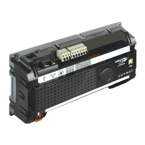
Page 5: Bus And Port Connections
CLIF-CBUSLC INTERFACE – INSTALLATION & COMMISSIONING INSTRUCTIONS Bus and Port Connections Overview WARNING Risk of electric shock or equipment damage! Do not touch any live parts in the cabinet! ► Fig. 3. Side view Disconnect the power supply before making connections ►... - Page 6 CLIF-CBUSLC INTERFACE – INSTALLATION & COMMISSIONING INSTRUCTIONS USB Driver Installation Windows 7 In order to connect the CLIF-CBUS Interface to the Windows 7 PC, you will need an USB cable of type A-Male-to-type-B- Male (Type B standard). The CLIF-CBUS Interface will be connected to the Windows 7 PC as shown in the following figure.
- Page 7 CLIF-CBUSLC INTERFACE – INSTALLATION & COMMISSIONING INSTRUCTIONS In Control Panel \ Device Manager \ Network Adapters Select No, let me choose what to do, and then select Install driver software from Windows Update if it is not found on my computer. Click the Save Changes button.
- Page 8 CLIF-CBUSLC INTERFACE – INSTALLATION & COMMISSIONING INSTRUCTIONS 21. Click Let me Pick from a list of device drivers on my computer. 22. Uncheck the Show compatible hardware box. 23. Select the Manufacturer Microsoft Corporation 24. Select Remote NDIS Compatible Device 25.
- Page 9 CLIF-CBUSLC INTERFACE – INSTALLATION & COMMISSIONING INSTRUCTIONS Click Let me pick from a list of device drivers on my Select USB-RNDIS-Adapter, and then click Next button. computer. RESULT: The Update Driver Warning message box displays. Confirm the warning by clicking Yes button. RESULT: The driver will be installed successfully as indicated by the final message box.
- Page 10 CLIF-CBUSLC INTERFACE – INSTALLATION & COMMISSIONING INSTRUCTIONS lower, the automatic installation does not work: Please down- LEDs load the appropriate USB driver prior to the installation at: The CLIF-CBUSLC features the following LEDs: http://catalog.update.microsoft.com/v7/site/ScopedViewRedire ct.aspx?updateid=37e35bd4-d788-4b83-9416-f78e439f90a2 Please connect the controller to the PC as described in section "Windows 8"...
- Page 11 CLIF-CBUSLC INTERFACE – INSTALLATION & COMMISSIONING INSTRUCTIONS Table 6. Required slide switch settings setting remarks DO NOT USE! BIAS DO NOT USE! For C-Bus communication, the switch must be in the leftmost position. 47 kOHM (MANDATORY!) RS485-1 (+) RS485-1 (-) 47 kOHM GND-1 Fig.
-
Page 12: Mounting/Dismounting
CLIF-CBUSLC INTERFACE – INSTALLATION & COMMISSIONING INSTRUCTIONS MOUNTING/DISMOUNTING Before Installation IMPORTANT To allow the evaporation of any condensation resulting from low shipping / storage temperatures, keep the device at room temperature for at least 24 h before applying power. US requirement, only: This device must be installed in a UL-listed enclosure offering adequate space to maintain the segregation of line voltage field wiring and Class 2 field wiring. -
Page 13: Wiring And Set-Up
CLIF-CBUSLC INTERFACE – INSTALLATION & COMMISSIONING INSTRUCTIONS WIRING AND SET-UP General Safety Considerations All wiring must comply with applicable electrical codes and ordinances, including VDE, National Electric Code (NEC) or equivalent, and any local regulations must be observed. Refer to job or manufacturer’s drawings for details. Local wiring guidelines (e.g., IEC 364-6-61 or VDE 0100) may take precedence over recommendations provided here. -
Page 14: Rin-Apu24
CPU 2 USB 2.0 Lightning Protection Device Interface 24V~0 24V~ 24V~0 24V~ Please contact your local Honeywell representative for CPU #1 CPU #2 information on lightning protection. REVERSED POLARITY! LINE 24 V~0 NOISE-FREE EARTH GROUND (ONLY ONE PER SYSTEM) Fig. -
Page 15: Engineering, Commissioning
CLIF-CBUSLC INTERFACE – INSTALLATION & COMMISSIONING INSTRUCTIONS ENGINEERING, COMMISSIONING 6. The configuration mask (see Fig. 18) will then appear. Enter the IP address, subnet mask, and default gateway Please refer also to ARENA / COACH – User Guide address. (Product Literature No.: EN2Z-0996GE51) for detailed Do not select "block SUSInet port"... -
Page 16: Extra Parts
CLIF-CBUSLC INTERFACE – INSTALLATION & COMMISSIONING INSTRUCTIONS EXTRA PARTS Table 12. Extra parts order no. description Removable terminal plugs, push-in type; complete set of 3 TPU-11-01 plugs (for terminals 1 - 47); for the CLAXEH00ND100A. Removable terminal plugs, push-in type; complete set of 9 TPU-45-01 plugs (for terminals 1 - 47);... -
Page 17: Lonworks Communications
IV 22 AWG (Belden part number PARK POSITION 9H2201504) non-shielded, twisted-pair, solid-conductor (NO TERMINATION) wire. When possible, use Honeywell AK3781, AK3782, AK3791, or AK3792 cable (US part numbers). See Excel 50/5000 FTT/LPT BUS FTT/LPT FREE Mechanisms (Product Literature no.: EN0B-... -
Page 18: C-Bus Connection
CLIF-CBUSLC INTERFACE – INSTALLATION & COMMISSIONING INSTRUCTIONS C-BUS CONNECTION The CLIF-CBUSLC features an RS485 interfaces to which C-Bus devices can be connected: RS485-1 (consisting of push-in terminals 24 [GND-1], 25, and 26). C-Bus Topologies Via the C-Bus, up to 30 C-Bus devices (e.g., controllers, etc.) can communicate with one another and a PC central. The C-Bus must be connected via the individual controllers (open ring). -
Page 19: Connecting Clif-Cbuslc Via Rs485-1 To C-Bus
CLIF-CBUSLC INTERFACE – INSTALLATION & COMMISSIONING INSTRUCTIONS Connecting CLIF-CBUSLC via RS485-1 to C-Bus NOTE: Always power each CLIF-CBUSLC and the connected C-Bus devices via separate transformers. NOTE: The max. C-Bus cable length is 1200 m (4000 ft). NOTE: If any devices are not electrically isolated, signal ground connection is recommended. See section "RS485 Standard" on pg. -
Page 20: Effect Of Poll Rate + Subscribed Points On Cpu Load
CLIF-CBUSLC INTERFACE – INSTALLATION & COMMISSIONING INSTRUCTIONS EFFECT OF POLL RATE + SUBSCRIBED POINTS ON CPU LOAD The poll rate set for the CLIF-CBUSLC and the chosen number of subscribed datapoints both make a demand on the CPU load. The following recommendations are therefore applicable. C-Bus-Related Size Recommendations Table 14. -
Page 21: Troubleshooting
CLIF-CBUSLC INTERFACE – INSTALLATION & COMMISSIONING INSTRUCTIONS TROUBLESHOOTING General The following LEDs of the CLIF-CBUSLC can be used for troubleshooting purposes: Power LED (green) Status LED (red) L2 LED (yellow) Tx (sending data on RS485-1) and Rx (receiving data on RS485-1) LED Power LED (green) of CLIF-CBUSLC Table 16. -
Page 22: Appendix 1: Earth Grounding
If system protective earth grounding is planned, use a ► cable as short as possible for grounding: To support SELV, all Honeywell external (CRT series) or min. 1.5 mm² (16 AWG). internal transformers comply with standard EN60742. Earth grounding is therefore not recommended. - Page 23 CLIF-CBUSLC INTERFACE – INSTALLATION & COMMISSIONING INSTRUCTIONS Example 2 When connecting multiple CPUs to a single transformer, it is imperative that the polarity of the power supply terminals of the CPUs and the polarity of the transformer always cor- respond (namely: 24V-0 of the transformer must always be connected to 24V-0 of the CPU, and 24V~ of the transformer must always be connected with 24V~ of the CPU).
-
Page 24: Index
LEDs, 5 details, 5 L2, 3, 10, 21 Manufactured for and on behalf of the Environmental & Energy Solutions Division of Honeywell Technologies Sàrl, Rolle, Z.A. La Pièce 16, Switzerland by its Authorized Representative: CentraLine Honeywell GmbH Böblinger Strasse 17 71101 Schönaich, Germany...
Need help?
Do you have a question about the Centra Line CLIF-CBUSLC and is the answer not in the manual?
Questions and answers