Advertisement
Welcome to the DM814x/AM387x Evaluation Module (EVM) Quick Start Guide. This guide is designed to help you
through the initial setup of your EVM. This EVM allows you to experience numerous demonstrations that showcase the
DM814x/AM387x processors. The DM814x/AM387 EVM includes:
• Hardware
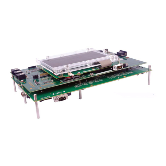
– DM814x/AM387x main board
– Expansion I/O daughtercard
– Interposer board and LCD
– Serial cable
– Ethernet cable
– Audio cable
– HDMI cable
– Universal power supply with regional adapter
– USB mouse
– Mini USB to USB adaptor cable
– SD card reader (plugs into USB port on PC)
– SD card: Contains Linux™ Software Development Kit
(SDK) and example applications
4 4
6 6
5 5
DM814x/AM387x EVM Baseboard
• Printed documents
– DM814x/AM387x EVM Quick Start Guide (this
document)
– Linux SDK SD card content sheet
– Software license agreement
– Ubuntu 10.04 LTS (on CD)
• Software and soft copy documents
– DM814x/AM387x Software Development Kit (on
SD card)
– Sourcery G++™ evaluation tools from CodeSourcery
8 8
9 9
2 2
1
1
3 3
7
7
Expansion I/O Board
Default setup (Linux boot from SD card)
1
For SD boot set up, configure S1
2
Configure SW2 switches (for
switches 1, 2, 3, 5 = ON; all
NAND and SPI) as OFF.
other switches OFF.
Figure 1.
Figure 2.
4
Connect the component cable
5
Connect the supplied Ethernet
to the TVP7002 port on the
cable to the RJ-45 jack on the
board (Figure 1).
board (J14 or J27). Connect
To enable HD, user will need to
the other end of the cable to
provide an external HD monitor
an Internet-ready connection
with an HDMI input to view the
(router/switch). This step is not
encode/decode demo. Connect
required for initial EVM start-
the supplied HDMI cable to the
up, it is optional. This step
HDMI connector J1 (Figure 2).
allows proper execution of
Connect the other end of the
example applications that use
cable to the user-supplied HD
Internet access.
monitor. Optionally, users may
choose to view the encode/
decode demo on the supplied
LCD.
3
Connect supplied serial cable
to UART (P2). Connect the
other end of the serial cable to
a PC. This step is not required
for initial EVM start-up, it is
optional. This step enables
viewing of console messages
on a PC terminal and changing
some of the default
parameters on the EVM.
Figure 3.
Figure 4. Mini USB
USB connector
ports on EVM
6
Connect the supplied USB
adaptor (Figure 3) to the
mouse. Then connect the mini
side of the adaptor to the USB
port (Figure 4) MI (J2 or J3).
Advertisement
Table of Contents

Related Manuals for Texas Instruments DM814 Series


Summary of Contents for Texas Instruments DM814 Series
- Page 1 Default setup (Linux boot from SD card) Welcome to the DM814x/AM387x Evaluation Module (EVM) Quick Start Guide. This guide is designed to help you through the initial setup of your EVM. This EVM allows you to experience numerous demonstrations that showcase the DM814x/AM387x processors.
- Page 2 For support questions, please contact: support.ti.com DM814x/AM387x e2e.ti.com/dm814x Important Notice: The products and services of Texas Instruments Incorporated and its subsidiaries e2e.ti.com/am387x described herein are sold subject to TI’s standard terms and conditions of sale. Customers are advised to obtain the most current and complete information about TI products and services before placing orders.
Need help?
Do you have a question about the DM814 Series and is the answer not in the manual?
Questions and answers