Vega VEGACAP 65 Operating Instructions Manual
Capacitive cable electrode for level detection
Hide thumbs
Also See for VEGACAP 65:
- Operating instructions manual (44 pages) ,
- Operating instructions manual (40 pages) ,
- Operating instructions manual (44 pages)

Subscribe to Our Youtube Channel
Related Manuals for Vega VEGACAP 65


Summary of Contents for Vega VEGACAP 65
- Page 1 Operating Instructions Capacitive cable electrode for level detection VEGACAP 65 Relay (DPDT) Document ID: 30016...
-
Page 2: Table Of Contents
How to proceed if a repair is necessary ................28 Dismount..........................30 Dismounting steps......................30 Disposal ......................... 30 Supplement ..........................31 Technical data ........................ 31 Dimensions ........................35 Industrial property rights ....................40 Trademark ........................40 VEGACAP 65 • Relay (DPDT) - Page 3 Contents Editing status: 2020-09-24 VEGACAP 65 • Relay (DPDT)
-
Page 4: About This Document
Symbols used Document ID This symbol on the front page of this instruction refers to the Docu- ment ID. By entering the Document ID on www.vega.com you will reach the document download. Information, tip, note This symbol indicates helpful additional information. -
Page 5: For Your Safety
During work on and with the device, the required personal protective equipment must always be worn. Appropriate use The VEGACAP 65 is a sensor for point level detection. You can find detailed information about the area of application in chapter " Product description". Operational reliability is ensured only if the instrument is properly used according to the specifications in the operating instructions manual as well as possible supplementary instructions. -
Page 6: Eu Conformity
That is why we have introduced an environment management system with the goal of continuously improving company environmental pro- tection. The environment management system is certified according to DIN EN ISO 14001. Please help us fulfil this obligation by observing the environmental instructions in this manual: • Chapter " Packaging, transport and storage" • Chapter " Disposal" VEGACAP 65 • Relay (DPDT) -
Page 7: Product Description
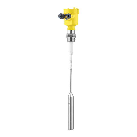
This operating instructions manual applies to the following instrument instructions versions: • Hardware from 1.0.0 • Software from 1.3.0 • Only for instrument versions without SIL qualification Constituent parts The VEGACAP 65 consists of the components: • Process fitting with probe • Housing with electronics • Housing lid VEGACAP 65 • Relay (DPDT) - Page 8 3 Product description Fig. 1: VEGACAP 65, cable version with plastic housing Housing lid Housing with electronics 3 Process fitting Type label The type label contains the most important data for identification and use of the instrument: VEGACAP 65 • Relay (DPDT)
- Page 9 Alternatively, you can access the data via your smartphone: • Download the VEGA Tools app from the " Apple App Store" or the " Google Play Store" • Scan the DataMatrix code on the type label of the instrument or •...
-
Page 10: Principle Of Operation
3 Product description Principle of operation Application area VEGACAP 65 is a point level sensor for use in all areas of industry. The partly insulated probe is suitable for measurement of bulk solids and liquids. The proven mechanical construction ensures a high functional safety. -
Page 11: Packaging, Transport And Storage
Protective cover The protective cover protects the sensor housing against soiling and intense heat from solar radiation. Flanges Screwed flanges are available in different versions according to the following standards: DIN 2501, EN 1092-1, BS 10, ASME B 16.5, JIS B 2210-1984, GOST 12821-80. VEGACAP 65 • Relay (DPDT) -
Page 12: Mounting
Chemical properties of the medium • Abrasion and mechanical influences Switching point In general, VEGACAP 65 must be mounted vertically. The instrument must be mounted in such a way that the probe is at the height of the requested switching point. Welding work Before beginning the welding work, remove the electronics module from the sensor. - Page 13 In the case of instrument housings with metric thread, the cable Cable glands glands are screwed in at the factory. They are sealed with plastic plugs as transport protection. You have to remove these plugs before electrical connection. VEGACAP 65 • Relay (DPDT)
-
Page 14: Mounting Instructions
Mounting instructions Agitators and fluidization Due to the effects of agitators, equipment vibration or similar, the level switch can be subjected to strong lateral forces. For this reason, do not use an overly long electrode for VEGACAP 65, but check if you can mount a short level switch on the side of the vessel in horizontal position. Inflowing medium If the instrument is mounted in the filling stream, unwanted false measurement signals can be generated. - Page 15 The probe must be mounted in a way that takes the arrangement of the filling and emptying apertures into account. To compensate measurement errors caused by the material cone in cylindrical vessels, the sensor must be mounted at a distance of d/6 from the vessel wall. Fig. 6: Filling and emptying centred VEGACAP 65 • Relay (DPDT)
- Page 16 Make sure that the max. permissible tensile load of the suspension cable is not exceeded. The danger of this happening exists particu- larly with very heavy solids and large meas. lengths. The max. permis- sible load is stated in chapter " Technical data". VEGACAP 65 • Relay (DPDT)
-
Page 17: Connecting To Power Supply
4. Insert the cable into the sensor through the cable entry 5. Lift the opening levers of the terminals with a screwdriver (see following illustration) 6. Insert the wire ends into the open terminals according to the wir- ing plan VEGACAP 65 • Relay (DPDT) -
Page 18: Wiring Plan, Single Chamber Housing
The electrical connection is finished. Fig. 8: Connection steps 5 and 6 Wiring plan, single chamber housing Housing overview Fig. 9: Material versions, single chamber housing Plastic (not with dust-Ex) Aluminium Stainless steel Filter element for air pressure compensation VEGACAP 65 • Relay (DPDT) - Page 19 DIL switch for mode adjustment Ground terminal Connection terminals Control lamp We recommend connecting VEGACAP 65 in such a way that the Wiring plan switching circuit is open when there is a level signal, line break or failure (safe state).
- Page 20 Inductive loads also result from the connection to a PLC input or output and/or in combination with long cables. It is imperative that you take measures to extinguish sparks to protect the relay contact (e.g. Z diode) or use an electronic version with transistor output. VEGACAP 65 • Relay (DPDT)
-
Page 21: Setup
Note: As a rule, always set the mode with the mode switch (3) before start- ing setup VEGACAP 65. The switching output will change if you set the mode switch (3) afterwards. This could possibly trigger other con- nected instruments or devices. - Page 22 1. Set mode switch (3) to mode min. detection) 2. Set meas. range selection switch (2) to range 1. 3. Lower the level to the requested min. level. 4. Turn the potentiometer (1) to 0, the control lamp (6) lights green. VEGACAP 65 • Relay (DPDT)
-
Page 23: Function Table
Mode of operation min. Dry run protection (6) (7) Relay energized Green Mode of operation min. Dry run protection (6) (7) Relay deenergized Failure of the supply volt- (min./max. mode) (6) (7) Relay deenergized Fault (6) (7) Relay deenergized flashes red VEGACAP 65 • Relay (DPDT) -
Page 24: Maintenance And Fault Rectification
24 hour service hotline Should these measures not be successful, please call in urgent cases the VEGA service hotline under the phone no. +49 1805 858550. The hotline is manned 7 days a week round-the-clock. Since we offer this service worldwide, the support is only available in the English language. The service is free, only standard call charges are incurred. - Page 25 Measuring probe Ground potential Depending on the reason for the fault and the measures taken, the Reaction after fault recti- fication steps described in chapter " Set up" may have to be carried out again. VEGACAP 65 • Relay (DPDT)
-
Page 26: Exchange Of The Electronics Module
9. Insert the electronics module carefully. Make sure that the plug is in the correct position. 10. Screw in and tighten the two holding screws with a screwdriver (Torx size T10 or Phillips 4) 11. Insert the wire ends into the open terminals according to the wir- ing plan VEGACAP 65 • Relay (DPDT) -
Page 27: Shortening Of The Probe
2. Pull the cable out of the gravity weight. 3. To avoid splicing of the steel cable, tin the cable before shortening with a soldering iron and tighten the wire. 4. Shorten the cable with a cut-off wheel or metal saw at the lower end. Make sure the length is correct before shortening. VEGACAP 65 • Relay (DPDT) -
Page 28: How To Proceed If A Repair Is Necessary
By doing this you help us carry out the repair quickly and without hav- ing to call back for needed information. If a repair is necessary, please proceed as follows: VEGACAP 65 • Relay (DPDT) - Page 29 Clean the instrument and pack it damage-proof • Attach the completed form and, if need be, also a safety data sheet outside on the packaging • Please contact the agency serving you to get the address for the return shipment. You can find the agency on our home page www.vega.com. VEGACAP 65 • Relay (DPDT)
-
Page 30: Dismount
Pass the instrument directly on to a specialised recycling company and do not use the municipal collecting points. If you have no way to dispose of the old instrument properly, please contact us concerning return and disposal. VEGACAP 65 • Relay (DPDT) -
Page 31: Supplement
Ʋ Pipe thread, conical (ASME B1.20.1) 1 NPT, 1½ NPT Cable connected electrically conductive with the gravity weight. Cable connected electrically conductive with the gravity weight. Aluminium, stainless steel precision casting and Ex d housing VEGACAP 65 • Relay (DPDT) - Page 32 Contact material (relay contacts) AgNi or AgSnO2 each with 3 µm gold plating Modes (switchable) Min./Max. Switching delay Ʋ When immersed 0.7 s Ʋ When laid bare 0.7 s Ʋ In the event of a fault VEGACAP 65 • Relay (DPDT)
- Page 33 Process temperature (thread or flange -50 … +200 °C (-58 … +392 °F) temperature) with temperature adapter (option) Process temperature VEGACAP 65 of St C22.8 Ʋ Insulation PTFE -20 … +80 °C (-4 … +176 °F) Ʋ Insulation PA -20 … +80 °C (-4 … +176 °F) Ʋ...
- Page 34 Voltage supply Operating voltage 20 … 253 V AC, 50/60 Hz, 20 … 72 V DC (at U >60 V DC, the ambient temperature can be max. 50 °C/122 °F) Power consumption 1 … 8 VA (AC), approximately 1 W (DC) Electrical protective measures Protection rating IP66/IP67 (NEMA Type 4X) VEGACAP 65 • Relay (DPDT)
-
Page 35: Dimensions
Dimensions The following dimensional drawings represent only an extract of all possible versions. Detailed dimensional drawings can be downloaded at www.vega.com/downloads under " Drawings". VEGACAP 65, housing ~ 69 mm ~ 59 mm ~ 69 mm ~ 116 mm (4.57") - Page 36 G 1½ ø 6 mm (0.24") ø 30 mm (1.18") Fig. 20: VEGACAP 65, cable version with ø 6 mm (0.236 in), threaded version G1 (ISO 228 T1) Sensor length, see chapter " Technical data" VEGACAP 65 • Relay (DPDT)
- Page 37 G 1½ ø 8 mm (0.32") ø 30 mm (1.18") Fig. 21: VEGACAP 65, cable version with ø 8 mm (0.315 in), threaded version G1 (ISO 228 T1) Sensor length, see chapter " Technical data" VEGACAP 65 • Relay (DPDT)
- Page 38 G 1 A ø 12 mm (0.47") ø 30 mm (1.18") Fig. 22: VEGACAP 65, cable version with ø 12 mm (0.472 in), threaded version G1 (ISO 228 T1) Sensor length, see chapter "Technical data" VEGACAP 65 • Relay (DPDT)
- Page 39 ø 40 mm (1.58") Fig. 23: Temperature adapter ø 16 mm (0.63") ø 27 mm (1.06") Fig. 24: VEGACAP 65, screening tube, for example against strong condensation Length of the screening tube, see chapter "Technical data" VEGACAP 65 • Relay (DPDT)
-
Page 40: Industrial Property Rights
Les lignes de produits VEGA sont globalement protégées par des droits de propriété intellec- tuelle. Pour plus d'informations, on pourra se référer au site www.vega.com. VEGA lineas de productos están protegidas por los derechos en el campo de la propiedad indus- trial. Para mayor información revise la pagina web www.vega.com. - Page 41 Notes VEGACAP 65 • Relay (DPDT)
- Page 42 Notes VEGACAP 65 • Relay (DPDT)
- Page 43 Notes VEGACAP 65 • Relay (DPDT)
- Page 44 Subject to change without prior notice © VEGA Grieshaber KG, Schiltach/Germany 2020 VEGA Grieshaber KG Phone +49 7836 50-0 Am Hohenstein 113...
Need help?
Do you have a question about the VEGACAP 65 and is the answer not in the manual?
Questions and answers