Vega VEGACAP 65 Operating Instructions Manual
Capacitive cable electrode for level
detection
Hide thumbs
Also See for VEGACAP 65:
- Operating instructions manual (44 pages) ,
- Operating instructions manual (36 pages) ,
- Operating instructions manual (44 pages)

Subscribe to Our Youtube Channel
Related Manuals for Vega VEGACAP 65


Summary of Contents for Vega VEGACAP 65
- Page 1 Operating Instructions Capacitive cable electrode for level detection VEGACAP 65 - contactless electronic switch Document ID: 30017...
-
Page 2: Table Of Contents
How to proceed if a repair is necessary ................28 Dismount Dismounting steps......................29 Disposal ......................... 29 Supplement Technical data ........................ 30 Dimensions ........................33 Industrial property rights ....................38 Trademark ........................38 VEGACAP 65 • - contactless electronic switch... - Page 3 To ensure reliable setup and operation of your VEGACAP 65, we offer accessories and replacement parts. The corresponding documenta- tions are: • 30174 - Electronics module VEGACAP series 60 • 34296 - Protective cover • 31088 - Flanges according to DIN-EN-ASME-JIS-GOST Editing status: 2016-02-19 VEGACAP 65 • - contactless electronic switch...
-
Page 4: About This Document
This arrow indicates a single action. Sequence of actions Numbers set in front indicate successive steps in a procedure. Battery disposal This symbol indicates special information about the disposal of bat- teries and accumulators. VEGACAP 65 • - contactless electronic switch... -
Page 5: For Your Safety
During work on and with the device the required personal protective equipment must always be worn. Appropriate use The VEGACAP 65 is a sensor for point level detection. You can find detailed information about the area of application in chapter "Product description". Operational reliability is ensured only if the instrument is properly used according to the specifications in the operating instructions manual as well as possible supplementary instructions. -
Page 6: Safety Label On The Instrument
That is why we have introduced an environment management system with the goal of continuously improving company environmental pro- tection. The environment management system is certified according to DIN EN ISO 14001. Please help us fulfill this obligation by observing the environmental instructions in this manual: • Chapter "Packaging, transport and storage" • Chapter "Disposal" VEGACAP 65 • - contactless electronic switch... -
Page 7: Product Description
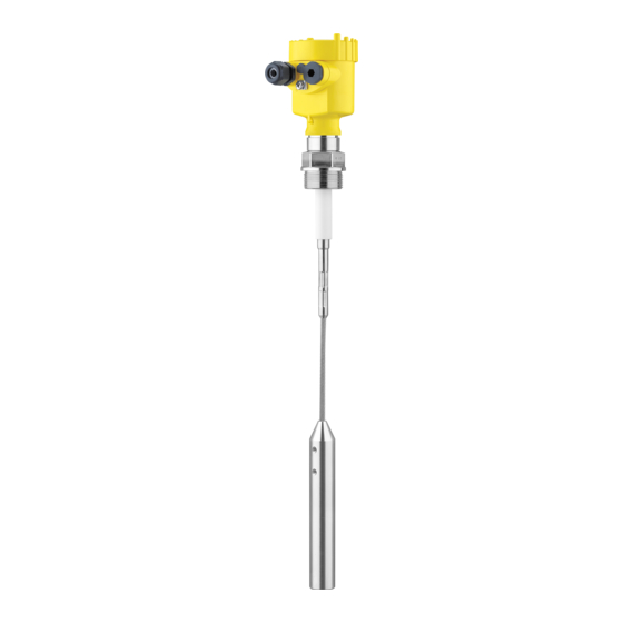
• Housing with electronics • Housing cover, optionally available with display and adjustment module Fig. 1: VEGACAP 65 - cable version with plastic housing Housing cover with integrated display and adjustment module (optional) Housing with electronics 3 Process fitting Type label... -
Page 8: Principle Of Operation
Principle of operation Area of application VEGACAP 65 is a point level sensor for use in all areas of industry. The partly insulated probe is suitable for measurement of bulk solids and liquids. The proven mechanical construction ensures a high functional safety. -
Page 9: Operation
The capacitance change is converted by the electronics module into a switching command. Voltage supply VEGACAP 65 is a compact instrument, i.e. it can be operated without external evaluation system. The integrated electronics evaluates the level signal and outputs a switching signal. With this switching signal, a connected device can be operated directly (e.g. a warning system,... -
Page 10: Accessories And Replacement Parts
The protective cover protects the sensor housing against soiling and intense heat from solar radiation. You will find additional information in the supplementary instructions manual "Protective cover" (Document-ID 34296). Flanges Screwed flanges are available in different versions according to the following standards: DIN 2501, EN 1092-1, BS 10, ASME B 16.5, JIS B 2210-1984, GOST 12821-80. You can find additional information in the supplementary instructions manual "Flanges according to DIN-EN-ASME-JIS". VEGACAP 65 • - contactless electronic switch... -
Page 11: Mounting
You can find the specifications in chapter "Technical data" and on the nameplate. Switching point In general, VEGACAP 65 must be mounted vertically. The instrument must be mounted in such a way that the probe is at the height of the requested switching point. Welding work Before beginning the welding work, remove the electronics module from the sensor. -
Page 12: Mounting Instructions
Mounting instructions Agitators and fluidization Due to the effects of agitators, equipment vibration or similar, the level switch can be subjected to strong lateral forces. For this reason, do not use an overly long electrode for VEGACAP 65, but check if you can mount a short level switch on the side of the vessel in horizontal position. Inflowing medium If the instrument is mounted in the filling stream, unwanted false measurement signals can be generated. - Page 13 The probe must be mounted in a way that takes the arrangement of the filling and emptying apertures into account. To compensate measurement errors caused by the material cone in cylindrical vessels, the sensor must be mounted at a distance of d/6 from the vessel wall. VEGACAP 65 • - contactless electronic switch...
- Page 14 4 Mounting Fig. 6: Filling and emptying centred Fig. 7: Filling in the centre, emptying laterally VEGACAP 65 Discharge opening Filling opening VEGACAP 65 • - contactless electronic switch...
- Page 15 Make sure that the max. permissible tensile load of the suspension Tensile load cable is not exceeded. The danger of this happening exists particu- larly with very heavy solids and large meas. lengths. The max. permis- sible load is stated in chapter "Technical data". VEGACAP 65 • - contactless electronic switch...
-
Page 16: Connecting To Power Supply
3. Remove approx. 10 cm (4 in) of the cable mantle, strip approx. 1 cm (0.4 in) of insulation from the ends of the individual wires 4. Insert the cable into the sensor through the cable entry 5. Lift the opening levers of the terminals with a screwdriver (see following illustration) 6. Insert the wire ends into the open terminals according to the wir- ing plan VEGACAP 65 • - contactless electronic switch... -
Page 17: Wiring Plan, Single Chamber Housing
Fig. 8: Connection steps 5 and 6 Wiring plan, single chamber housing Housing overview Fig. 9: Material versions, single chamber housing Plastic (not with dust-Ex) Aluminium Stainless steel Filter element for air pressure compensation VEGACAP 65 • - contactless electronic switch... - Page 18 Connection terminals Control lamp Wiring plan We recommend connecting VEGACAP 65 in such a way that the switching circuit is open when there is a level signal, line break or failure (safe state). The contactless electronic switch is always shown in non-operative condition.
- Page 19 5 Connecting to power supply When VEGACAP 65 is used as part of an overfill protection system according to WHG, also note the regulations of the general type ap- proval. Fig. 11: Wiring plan Voltage supply VEGACAP 65 • - contactless electronic switch...
-
Page 20: Setup
DIL switch for mode adjustment - min./max. • Control lamp Note: As a rule, always set the mode with the mode switch (3) before start- ing setup VEGACAP 65. The switching output will change if you set the mode switch (3) afterwards. This could possibly trigger other con- nected instruments or devices. Adjustment elements Fig. 12: Oscillator - Contactless electronic switch Potentiometer for switching point adaptation... - Page 21 When the control lamp (6) lights green: continue with the next item. 5. Turn the potentiometer (1) very slowly anticlockwise until the control lamp (6) lights red. The measuring system is now ready for operation. Mode min. (min. level 1. Set mode switch (3) to mode min. detection) 2. Set meas. range selection switch (2) to range 1. 3. Lower the level to the requested min. level. 4. Turn the potentiometer (1) to 0, the control lamp (6) lights green. VEGACAP 65 • - contactless electronic switch...
-
Page 22: Function Table
Mode max. Overflow protec- tion Switch open Mode min. Dry run protection Switch closed Green Mode min. Dry run protection Switch open Failure of the sup- ply voltage (min./max. mode) Switch open Fault Switch open flashes red VEGACAP 65 • - contactless electronic switch... -
Page 23: Maintenance And Fault Rectification
24 hour service hotline Should these measures not be successful, please call in urgent cases the VEGA service hotline under the phone no. +49 1805 858550. The hotline is manned 7 days a week round-the-clock. Since we offer this service worldwide, the support is only available in the English language. The service is free, only standard call charges are incurred. - Page 24 Check the resistance in Remove the electronics module. Check the resistance between the the probe two plug connections. There must no longer be a connection (high impedance). If there is still a connection - exchange the instrument or return it for repair VEGACAP 65 • - contactless electronic switch...
-
Page 25: Exchange Of The Electronics Module
Downloads. Proceed as follows: 1. Switch off power supply 2. Unscrew the housing lid 3. Lift the opening levers of the terminals with a screwdriver 4. Pull the connection cables out of the terminals 5. Loosen the two screws with a screw driver (Torx size T10 or slot VEGACAP 65 • - contactless electronic switch... - Page 26 13. Check the hold of the wires in the terminals by lightly pulling on them 14. Check cable gland on tightness. The seal ring must completely encircle the cable. 15. Mount the probe into the vessel. Make sure that the probe is uncovered. VEGACAP 65 • - contactless electronic switch...
-
Page 27: Shortening Of The Probe
3. To avoid splicing of the steel cable, tin the cable before shortening with a soldering iron and tighten the wire. 4. Shorten the cable with a cut-off wheel or metal saw at the lower end. Make sure the length is correct before shortening. Fig. 32: Take the gravity weight into account and shorten the cable respectively VEGACAP 65 • - contactless electronic switch... -
Page 28: How To Proceed If A Repair Is Necessary
Clean the instrument and pack it damage-proof • Attach the completed form and, if need be, also a safety data sheet outside on the packaging • Please contact the agency serving you to get the address for the return shipment. You can find the agency on our home page www.vega.com. VEGACAP 65 • - contactless electronic switch... -
Page 29: Dismount
WEEE directive. Correct disposal avoids negative effects on humans and the environ- ment and ensures recycling of useful raw materials. Materials: see chapter "Technical data" If you have no way to dispose of the old instrument properly, please contact us concerning return and disposal. VEGACAP 65 • - contactless electronic switch... -
Page 30: Supplement
1 NPT, 1½ NPT (ASME B1.20.1) Ʋ Flanges DIN from DN 50, ASME from 2" Weight Ʋ Instrument weight (depending on 0.8 … 4 kg (0.18 … 8.82 lbs) process fitting) Ʋ Gravity weight 900 g (32 oz) Cable connected electrically conductive with the gravity weight. Cable connected electrically conductive with the gravity weight. VEGACAP 65 • - contactless electronic switch... - Page 31 < 0.15 %/10 K of the adjusted measuring range Ambient conditions Ambient temperature on the housing -40 … +80 °C (-40 … +176 °F) Storage and transport temperature -40 … +80 °C (-40 … +176 °F) Process conditions Process pressure Ʋ Standard -1 … +64 bar/-100 … 6400 kPa (-14.5 … 928 psig) Ʋ with screening tube adapter (PN1) 0 … +1 bar/0 … 100 kPa (0 … 14.5 psig) Distance from the process fittings to the set switching point Distance from the process fittings to the set switching point VEGACAP 65 • - contactless electronic switch...
- Page 32 Min. detection or dry run protection Ʋ Max. Max. detection or overflow protection DIL switch for measuring range selection Ʋ range 1 0 … 20 pF Ʋ range 2 0 … 85 pF Ʋ range 3 0 … 450 pF VEGACAP 65 • - contactless electronic switch...
-
Page 33: Dimensions
Protection class Approvals Instruments with approvals can have different technical specifications depending on the version. For that reason the associated approval documents of these instruments have to be carefully noted. They are part of the delivery or can be downloaded under www.vega.com, "VEGA Tools" and "Instrument search" as well as in the general download area. Dimensions VEGACAP 65, housing ~ 69 mm... - Page 34 ø 6 mm (0.24") ø 30 mm (1.18") Fig. 36: VEGACAP 65, cable version with ø 6 mm (0.236 in), threaded version G1 (ISO 228 T1) = Sensor length, see chapter "Technical data" VEGACAP 65 • - contactless electronic switch...
- Page 35 ø 8 mm (0.32") ø 30 mm (1.18") Fig. 37: VEGACAP 65, cable version with ø 8 mm (0.315 in), threaded version G1 (ISO 228 T1) = Sensor length, see chapter "Technical data" VEGACAP 65 • - contactless electronic switch...
- Page 36 ø 12 mm (0.47") ø 30 mm (1.18") Fig. 38: VEGACAP 65, cable version with ø 12 mm (0.472 in), threaded version G1 (ISO 228 T1) = Sensor length, see chapter "Technical data" VEGACAP 65 • - contactless electronic switch...
- Page 37 ø 40 mm (1.58") Fig. 39: Temperature adapter ø 16 mm (0.63") ø 27 mm (1.06") Fig. 40: VEGACAP 65, screening tube, for example against strong condensation Length of the screening tube, see chapter "Technical data" VEGACAP 65 • - contactless electronic switch...
-
Page 38: Industrial Property Rights
Les lignes de produits VEGA sont globalement protégées par des droits de propriété intellec- tuelle. Pour plus d'informations, on pourra se référer au site www.vega.com. VEGA lineas de productos están protegidas por los derechos en el campo de la propiedad indus- trial. Para mayor información revise la pagina web www.vega.com. - Page 39 Notes VEGACAP 65 • - contactless electronic switch...
- Page 40 Subject to change without prior notice © VEGA Grieshaber KG, Schiltach/Germany 2016 VEGA Grieshaber KG Phone +49 7836 50-0 Am Hohenstein 113...
Need help?
Do you have a question about the VEGACAP 65 and is the answer not in the manual?
Questions and answers