Vega VEGACAP 62 Operating Instructions Manual
Capacitive rod electrode for level detection
Hide thumbs
Also See for VEGACAP 62:
- Operating instructions manual (40 pages) ,
- Operating instructions manual (36 pages) ,
- Operating instructions manual (36 pages)

Subscribe to Our Youtube Channel
Related Manuals for Vega VEGACAP 62


Summary of Contents for Vega VEGACAP 62
- Page 1 Operating Instructions Capacitive rod electrode for level detection VEGACAP 62 Relay (DPDT) Document ID: 30004...
-
Page 2: Table Of Contents
How to proceed if a repair is necessary ................29 Dismount..........................30 Dismounting steps......................30 Disposal ......................... 30 Supplement ..........................31 Technical data ........................ 31 Dimensions ........................34 Industrial property rights ....................38 Trademark ........................38 VEGACAP 62 • Relay (DPDT) - Page 3 Contents Editing status: 2020-09-24 VEGACAP 62 • Relay (DPDT)
-
Page 4: About This Document
Symbols used Document ID This symbol on the front page of this instruction refers to the Docu- ment ID. By entering the Document ID on www.vega.com you will reach the document download. Information, tip, note This symbol indicates helpful additional information. -
Page 5: For Your Safety
During work on and with the device, the required personal protective equipment must always be worn. Appropriate use The VEGACAP 62 is a sensor for point level detection. You can find detailed information about the area of application in chapter " Product description". Operational reliability is ensured only if the instrument is properly used according to the specifications in the operating instructions manual as well as possible supplementary instructions. -
Page 6: Eu Conformity
That is why we have introduced an environment management system with the goal of continuously improving company environmental pro- tection. The environment management system is certified according to DIN EN ISO 14001. Please help us fulfil this obligation by observing the environmental instructions in this manual: • Chapter " Packaging, transport and storage" • Chapter " Disposal" VEGACAP 62 • Relay (DPDT) -
Page 7: Product Description
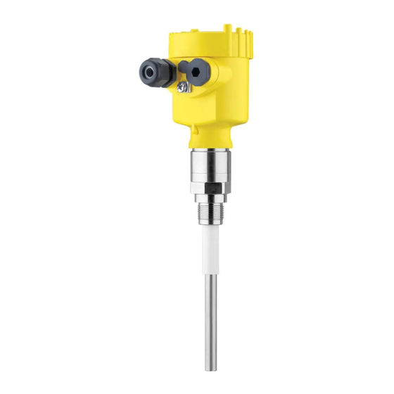
Only for instrument versions without SIL qualification Constituent parts The VEGACAP 62 consists of the components: • Process fitting with probe • Housing with electronics • Housing lid Fig. 1: VEGACAP 62, rod version with plastic housing Housing lid Housing with electronics 3 Process fitting VEGACAP 62 • Relay (DPDT) - Page 8 Alternatively, you can access the data via your smartphone: • Download the VEGA Tools app from the " Apple App Store" or the " Google Play Store" • Scan the DataMatrix code on the type label of the instrument or •...
-
Page 9: Principle Of Operation
3 Product description Principle of operation Application area VEGACAP 62 is a point level sensor for use in all areas of industry. The partly insulated probe is suitable for the measurement of bulk solids and liquids. The proven mechanical construction offers high functional safety. Functional principle Probe, measured product and vessel wall form an electrical capacitor. -
Page 10: Packaging, Transport And Storage
Protective cover The protective cover protects the sensor housing against soiling and intense heat from solar radiation. Flanges Screwed flanges are available in different versions according to the following standards: DIN 2501, EN 1092-1, BS 10, ASME B 16.5, JIS B 2210-1984, GOST 12821-80. VEGACAP 62 • Relay (DPDT) -
Page 11: Mounting
Use the recommended cables (see chapter " Connecting to power supply") and tighten the cable gland. You can give your instrument additional protection against moisture penetration by leading the connection cable downward in front of the cable gland. Rain and condensation water can thus drain off. This VEGACAP 62 • Relay (DPDT) - Page 12 Condensation If condensate forms on the vessel top, the run-off liquid can cause bridging and hence faulty switchings. For this reason, use a screening tube or a longer insulation. The length depends on the amount of condensate and the drain-off be- haviour of the product. VEGACAP 62 • Relay (DPDT)
-
Page 13: Mounting Instructions
Agitators and fluidization Due to the effects of agitators, equipment vibration or similar, the level switch can be subjected to strong lateral forces. For this reason, do not use an overly long electrode for VEGACAP 62, but check if you can mount a short level switch on the side of the vessel in horizontal position. Extreme vibration caused by the system, e.g. due to agitators or turbulence in the vessel from fluidisation, can cause the probe of VEGACAP 62 to vibrate in resonance. - Page 14 To achieve a very precise switching point, you can install VEGACAP 62 horizontally. However, if the switching point can have a tolerance of a few centimeters, we recommend mounting VEGACAP 62 approx. 20° inclined to the vessel bottom to avoid buildup. Install rod probes in such a way that the probe projects freely into the vessel. When the instrument is mounted in a tube or nozzle, buildup...
- Page 15 The probe must be mounted in a way that takes the arrangement of the filling and emptying apertures into account. To compensate measurement errors caused by the material cone in cylindrical vessels, the sensor must be mounted at a distance of d/6 from the vessel wall. Fig. 7: Filling and emptying centred VEGACAP 62 • Relay (DPDT)
- Page 16 4 Mounting Fig. 8: Filling in the centre, emptying laterally VEGACAP 62 Discharge opening Filling opening VEGACAP 62 • Relay (DPDT)
-
Page 17: Connecting To Power Supply
4. Insert the cable into the sensor through the cable entry 5. Lift the opening levers of the terminals with a screwdriver (see following illustration) 6. Insert the wire ends into the open terminals according to the wir- ing plan VEGACAP 62 • Relay (DPDT) -
Page 18: Wiring Plan, Single Chamber Housing
The electrical connection is finished. Fig. 9: Connection steps 5 and 6 Wiring plan, single chamber housing Housing overview Fig. 10: Material versions, single chamber housing Plastic (not with dust-Ex) Aluminium Stainless steel Filter element for air pressure compensation VEGACAP 62 • Relay (DPDT) - Page 19 DIL switch for mode adjustment Ground terminal Connection terminals Control lamp We recommend connecting VEGACAP 62 in such a way that the Wiring plan switching circuit is open when there is a level signal, line break or failure (safe state).
- Page 20 Inductive loads also result from the connection to a PLC input or output and/or in combination with long cables. It is imperative that you take measures to extinguish sparks to protect the relay contact (e.g. Z diode) or use an electronic version with transistor output. VEGACAP 62 • Relay (DPDT)
-
Page 21: Setup
Note: As a rule, always set the mode with the mode switch (3) before start- ing setup VEGACAP 62. The switching output will change if you set the mode switch (3) afterwards. This could possibly trigger other con- nected instruments or devices. - Page 22 In some cases the lowest range (range 1 = highest sensitivity) is not sufficient to adjust the full switch point. This would make another filling procedure necessary. For this reason we recommend setting and noting the empty switching point in all three meas. ranges. Set the meas. range se- VEGACAP 62 • Relay (DPDT)
- Page 23 1. Set mode switch (3) to mode min. detection) 2. Set meas. range selection switch (2) to range 1. 3. Lower the level to the requested min. level. 4. Turn the potentiometer (1) to 0, the control lamp (6) lights green. VEGACAP 62 • Relay (DPDT)
-
Page 24: Function Table
Mode of operation min. Dry run protection (6) (7) Relay energized Green Mode of operation min. Dry run protection (6) (7) Relay deenergized Failure of the supply volt- (min./max. mode) (6) (7) Relay deenergized Fault (6) (7) Relay deenergized flashes red VEGACAP 62 • Relay (DPDT) -
Page 25: Maintenance And Fault Rectification
24 hour service hotline Should these measures not be successful, please call in urgent cases the VEGA service hotline under the phone no. +49 1805 858550. The hotline is manned 7 days a week round-the-clock. Since we offer this service worldwide, the support is only available in the English language. The service is free, only standard call charges are incurred. - Page 26 Measuring probe Ground potential Depending on the reason for the fault and the measures taken, the Reaction after fault recti- fication steps described in chapter " Set up" may have to be carried out again. VEGACAP 62 • Relay (DPDT)
-
Page 27: Exchange Of The Electronics Module
9. Insert the electronics module carefully. Make sure that the plug is in the correct position. 10. Screw in and tighten the two holding screws with a screwdriver (Torx size T10 or Phillips 4) 11. Insert the wire ends into the open terminals according to the wir- ing plan VEGACAP 62 • Relay (DPDT) -
Page 28: Shortening Of The Probe
2. Mount the probe into the vessel. Make sure that the probe is uncovered. Fig. 17: Compensation key Measuring range selection switch (compensation key) Control lamp 3. Keep the measuring range selection switch (1) pushed until the control lamp (2) flashes green. 4. Hence the probe is compensated to the modified length. VEGACAP 62 • Relay (DPDT) -
Page 29: How To Proceed If A Repair Is Necessary
Clean the instrument and pack it damage-proof • Attach the completed form and, if need be, also a safety data sheet outside on the packaging • Please contact the agency serving you to get the address for the return shipment. You can find the agency on our home page www.vega.com. VEGACAP 62 • Relay (DPDT) -
Page 30: Dismount
Pass the instrument directly on to a specialised recycling company and do not use the municipal collecting points. If you have no way to dispose of the old instrument properly, please contact us concerning return and disposal. VEGACAP 62 • Relay (DPDT) -
Page 31: Supplement
½ NPT, ¾ NPT, 1 NPT, 1½ NPT Ʋ Flanges DIN from DN 20, ASME from 1" Weight Ʋ Instrument weight (depending on 0.8 … 4 kg (0.18 … 8.82 lbs) process fitting) Aluminium, stainless steel precision casting and Ex d housing VEGACAP 62 • Relay (DPDT) - Page 32 < 3 % of the adjusted measuring range electromagnetic fields acc. to EN 61326 Influence of the ambient temperature < 0.15 %/10 K of the adjusted measuring range Ambient conditions Ambient temperature on the housing -40 … +80 °C (-40 … +176 °F) Distance from the process fittings to the set switching point. Distance from the process fittings to the set switching point. VEGACAP 62 • Relay (DPDT)
- Page 33 0 … +1 bar/0 … 100 kPa (0 … 14.5 psig) Process temperature VEGACAP 62 of -50 … +150 °C (-58 … +302 °F) 316L Process temperature VEGACAP 62 of St -20 … +150 °C (-4 … +302 °F) C22.8 Process temperature (thread or flange -50 …...
-
Page 34: Dimensions
They are part of the delivery or can be downloaded by entering the serial number of your instrument into the search field under www.vega.com as well as in the general download area. Dimensions The following dimensional drawings represent only an extract of all possible versions. Detailed dimensional drawings can be downloaded at www.vega.com/downloads under " Drawings". VEGACAP 62 • Relay (DPDT) - Page 35 Stainless steel single chamber (precision casting) Aluminium - single chamber G ¾, G 1, G 1½ ø 16 mm (0.63") 12 mm (0.47") Fig. 20: VEGACAP 62, threaded version G1 (ISO 228 T1) Sensor length, see chapter "Technical data" VEGACAP 62 • Relay (DPDT)
- Page 36 ø 40 mm (1.58") Fig. 21: Temperature adapter ø 16 mm (0.63") ø 27 mm (1.06") Fig. 22: VEGACAP 62, screening tube, for example against strong condensation Length of the screening tube, see chapter "Technical data" VEGACAP 62 • Relay (DPDT)
- Page 37 9 Supplement ø 27 mm (1.06") Fig. 23: VEGACAP 62, concentric tube, for example with small dielectric constant or for linearization Concentric tube length, see chapter "Technical data" VEGACAP 62 • Relay (DPDT)
-
Page 38: Industrial Property Rights
Les lignes de produits VEGA sont globalement protégées par des droits de propriété intellec- tuelle. Pour plus d'informations, on pourra se référer au site www.vega.com. VEGA lineas de productos están protegidas por los derechos en el campo de la propiedad indus- trial. Para mayor información revise la pagina web www.vega.com. - Page 39 Notes VEGACAP 62 • Relay (DPDT)
- Page 40 Subject to change without prior notice © VEGA Grieshaber KG, Schiltach/Germany 2020 VEGA Grieshaber KG Phone +49 7836 50-0 Am Hohenstein 113...
Need help?
Do you have a question about the VEGACAP 62 and is the answer not in the manual?
Questions and answers