Danfoss Maneurop NTZ Series Selection & Application Manuallines
Reciprocating compressors
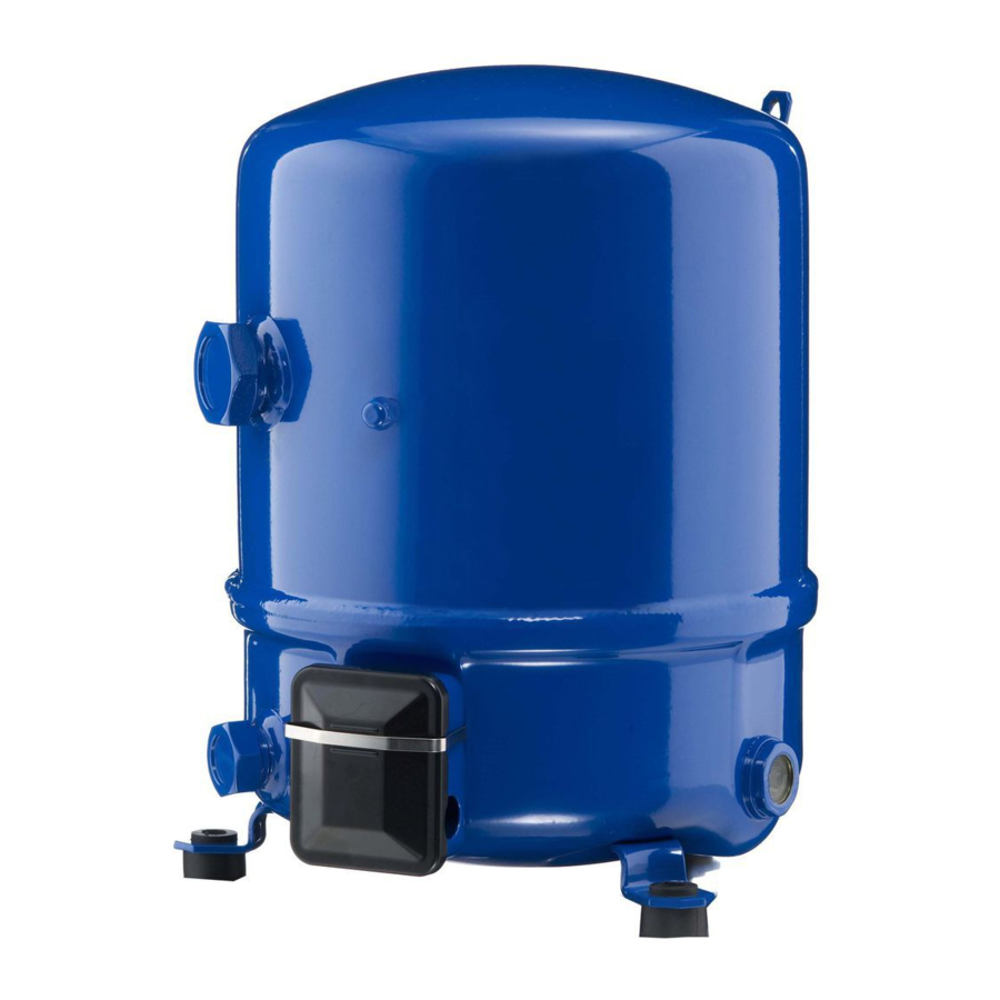
Hide thumbs
Also See for Maneurop NTZ Series:
- Application manuallines (34 pages) ,
- Application manuallines (24 pages)

Related Manuals for Danfoss Maneurop NTZ Series


Summary of Contents for Danfoss Maneurop NTZ Series
- Page 1 MAKING MODERN LIVING POSSIBLE Maneurop® reciprocating compressors R404A - R507A SELECTION & APPLICATION GUIDELINES...
-
Page 3: Table Of Contents
CONTENTS MANEUROP® RECIPROCATING COMPRESSORS ......................Features ....................................................Compressor reference ..........................................INTRODUCTION ................................................Code numbers ................................................Packaging .................................................... SPECIFICATIONS ................................................Technical specifi cations and nominal ratings ........................Approvals and certifi cates ....................................... Operating envelope ............................................. OUTLINE DRAWINGS ............................................1 cylinder ..................................................... 2 cylinders .................................................. -
Page 4: Maneurop® Reciprocating Compressors
MANEUROP® RECIPROCATING COMPRESSORS Features The Maneurop® NTZ series from A liquid injection system is not re- Danfoss Commercial Compressors quired. All components are of high is a range of hermetic reciprocating quality and precision to assure a long compressors for low evaporating tem- product life. -
Page 5: Introduction
The code numbers for NTZ compres- tables list the code numbers for NTZ (for ordering) sors are according to the standard compressors in single packs and Danfoss numbering system. Below industrial packs. Code no. NTZ compressors in single pack* Motor voltage code... -
Page 6: Specifications
8058 1.21 (*) Motor code 4 operating conditions: R404A, Evap. temp.: -35°C, Cond. temp.: 40°C, RGT: 20°C, SC: 0K For full NTZ data details and capacity tables refer to Online Datasheet Generator: www.danfoss.com/odsg Versions Available equipment version: connections, 3/8" fl are oil equalisation R1: Rotolock suction and discharge connection, threaded sight glass. -
Page 7: Outline Drawings
OUTLINE DRAWINGS 1 cylinder ø 224 Suction rotolock 1”1/4 Schrader 1/4” Discharge rotolock 1” Oil equalisation 3/8” PTC crankcase heater 33° 35° Threaded oil sight glass Silent block HM8-40 Suction 147 Discharge 142 17° Rotolock connections size Pipe sizing Rotolock valve Suction Discharge Suction... -
Page 8: Cylinders
OUTLINE DRAWINGS 2 cylinders ø 288 Suction rotolock Schrader 1"3/4 1/4" Discharge rotolock 1"1/4 Oil equalisation 3/8" crankcase heater Threaded oil sight glass Silent block Suction 179 HM8-40 Discharge 176 Rotolock connections size Pipe sizing Rotolock valve Suction Discharge Suction Discharge Suction Discharge... -
Page 9: Cylinders
OUTLINE DRAWINGS 4 cylinders ø 352 Suction rotolock 1"3/4 Discharge rotolock 1"1/4 Oil equalisation 3/8" (VE version only) Schrader 1/4" Threaded oil sight glass Mounting hole for PTC crankcase heater Silent block HM12-50 Rotolock connections size Pipe sizing Rotolock valve Suction Discharge Suction... -
Page 10: Electrical Connections And Wiring
ELECTRICAL CONNECTIONS AND WIRING Voltage application range Motor voltage code Nominal voltage Voltage application range 208-230 V / 1 / 60 Hz 187 – 253 V 200-230 V / 3 / 60 Hz 180 – 253 V 380-400 V / 3 / 50 Hz 340 –... -
Page 11: Nominal Capacitor Values And Relays
ELECTRICAL CONNECTIONS AND WIRING Nominal capacitor values 50 Hz PSC/CSR* CSR only Start and relays Start capacitors capacitors Models relay (A) μF (C) μF (B) μF NTZ048 3ARR3J4A4 NTZ068 PSC: Permanent Split Capacitor 60 Hz PSC/CSR* CSR only CSR: Capacitor Start Run Start Run capacitors: 440 volts Start... - Page 12 ELECTRICAL CONNECTIONS AND WIRING Single phase CSR wiring with trickle circuit Motor protector A & C Run capacitors Start capacitor Common Start winding (auxiliary) Run winding (main) Single phase CSR wiring without trickle circuit Motor protector A + C Run capacitors Start capacitor Common Start winding (auxiliary)
-
Page 13: Three Phase Electrical Characteristics
ELECTRICAL CONNECTIONS AND WIRING Three phase electrical characteristics Winding resistance (Locked Rotor Amp) (Maximum Continuous Current) (between phases +/- 7% at 25°C) Compressor model NTZ048 10.1 2.80 11.55 13.10 NTZ068 48.5 14.8 1.58 7.11 9.70 NTZ096 20.4 10.1 1.20 5.03 NTZ108 21.4 12.1... - Page 14 ELECTRICAL CONNECTIONS AND WIRING Wiring diagram with pump-down cycle Control device ..................... Optional short cycle timer (3 min) 5 pts 180 s ..Control relay ....................Liquid Solenoid valve LLSV ..............Compressor contactor ..............Safety lock out relay ................Pump-down control & L.P. switch ........
-
Page 15: Refrigerants And Lubricants
R404A and R507A are es- thermodynamic properties than pecially suitable for low and medium R404A and R507A. Especially their temperature applications. Danfoss larger temperature glide shall not be recommends the use of these refriger- neglected. Using these refrigerants the ants with NTZ compressors. -
Page 16: System Design Recommendations
For guidelines on manifolding ternating power supply. Danfoss does Maneurop® NTZ compressors, please not warrant the compressors for use refer to literature called "Parallel Appli- on mobile applications such as trucks, cation Guidelines". - Page 17 For servicing of existing installations refrigerating capacity and the system where acid formation is present the refrigerant charge. Danfoss DCL solid core fi lter driers Suction pressure control An MOP-type expansion valve or suc- When compressors are mounted onto tion pressure regulator (i.e. Danfoss...
-
Page 18: Operating Limits
SYSTEM DESIGN RECOMMENDATIONS Operating limits High pressure A high-pressure (HP) safety switch is ated with a manual reset device to required to shut down the compressor prevent cycling around the high pres- should the discharge pressure exceed sure limit. the values shown in the table below. If a discharge valve is used, the HP This switch can be set at lower values switch must be connected to the serv-... -
Page 19: Motor Protection
An accessory kit is value of 135°C when the compres- available from Danfoss which includes... -
Page 20: Liquid Refrigerant Control And Charge Limits
SYSTEM DESIGN RECOMMENDATIONS the thermostat, mounting bracket indicated below at no more than and insulation. The thermostat must 150 mm from the discharge connec- be attached to the discharge line as tion. Thermostat Discharge line Bracket Insulation Liquid refrigerant control Refrigeration compressors are basi- Liquid refrigerant will dilute the oil, and charge limits... - Page 21 As a general rule, Danfoss Commercial ing operation or after the defrost op- Compressors recommends to size the eration. This device also helps protect...
-
Page 22: Sound And Vibration Management
SOUND AND VIBRATION MANAGEMENT Sound Compressors in operation are one of a refrigeration system. Both phenom- the sources of sound and vibration in ena are closely related. Sound produced by a compressor is pressors are 100% suction gas cooled transmitted in every direction by the and require no external cooling they ambient air, the mounting feet, the can be insulated or enclosed in a sound... -
Page 23: Installation And Service
INSTALLATION AND SERVICE System cleanliness System contamination is one of the If fl ux is used, take every precaution main factors that aff ects equipment to prevent the leakage of fl ux into reliability and compressor service life. the piping. The use of fl ux core or Therefore it is important to take care fl ux coated braze wire or rod instead of the system cleanliness when as-... -
Page 24: System Pressure Test
INSTALLATION AND SERVICE Compressor connection New compressors have a protective sleeves or valves may be brazed to the to the system nitrogen holding charge. Only remove pipes when mounted on the compres- the suction and discharge plugs just sor. In this situation nitrogen or CO before connecting the compressor to must be purged through the compres- the installation, so as to prevent air... -
Page 25: Leak Detection
INSTALLATION AND SERVICE Leak detection Whenever possible the compressor oxygen, dry air or acetylene as these must be kept isolated from the sys- gasses can form an infl ammable mix- tem during leak detection by closing ture with the compressor oil. Never the suction and discharge valves Use use CFC or HCFC refrigerants for leak a mixture of nitrogen and the fi nal re-... - Page 26 Normally recommended. Always use Danfoss the quantity of oil added should be no 160Z lubricant for systems with NTZ more than 2% of the total refrigerant compressors and R404A or R507A.
- Page 28 And, we back technical solutions with business solution to help your company reduce costs, streamline processes and achieve your business goals. Danfoss A/S • www.danfoss.com FRCC.PC.002.A2.02 - Replace FRCC.PC.002.A1.02 May 2005 Produced by Danfoss CC- DSS - 02/2007...
Need help?
Do you have a question about the Maneurop NTZ Series and is the answer not in the manual?
Questions and answers