Advertisement
Quick Links
Y
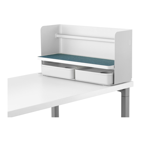
Parts Included:
A
Organizer
D
Slim Screen
F
Rail Mounted Shelf
Z
© 2016 Herman Miller, Inc. Zeeland, Michigan. Printed in the U.S.A.
Part no. 1BHH19 rev C.
Y, L, Canvas are among the trademarks of Herman Miller, Inc.
TM
Illustrations and specifi cations are based on the latest product information available at the time of publication.
The right is reserved to make changes in design and specifi cations at any time, without notice, and also to discontinue products.
Ubi
Work Tools Work Tools Installation and Disas-
™
sembly for Recycling Instructions
YT100./YT150.
B
YT500.
YT200.
E
Liner (2)
YT540.
YT300.
G
Surface Mounted Shelf
C
Liner
Surface Clamp
AN
Steel Screen
AP
H
Liner
YT510.
K
8-32 x 5/16 Truss Head
Machine Screw (4)
YT460.
YT250.
14-10 x 5/16 Torx Head
Sheet Metal Screw (6)
J
Back Drop
1
Advertisement

Subscribe to Our Youtube Channel
Related Manuals for HermanMiller Ubi Work Tools


Summary of Contents for HermanMiller Ubi Work Tools
- Page 1 Work Tools Work Tools Installation and Disas- ™ sembly for Recycling Instructions Parts Included: YT100./YT150. Liner Surface Clamp YT500. YT460. Organizer YT200. YT250. Steel Screen Liner (2) 14-10 x 5/16 Torx Head Slim Screen Sheet Metal Screw (6) YT540. YT300. Liner YT510.
- Page 2 YT330. YT320. Monitor Platform Liner Liner Shelf Freestanding Shelf YT530. YT500. YT400. YT410. YT410.S YT410.M YT410.P Nametag Document Clip YT440. YT430. Cord Cleat Rod Bookend © 2016 Herman Miller, Inc. Zeeland, Michigan. Printed in the U.S.A. Part no. 1BHH19 rev C. Y, L, Canvas are among the trademarks of Herman Miller, Inc.
- Page 3 YT420. Power Cord USB Hub coverter Puck Plate Double Face #6 x 1/4 Flat Head Thread #8 x 3/4 Pan Head 8-32 x 5/16 Truss Head Tape Forming Screw (2) Wood Screw (2) Machine Screw (2) YT450. YT550. Alcohol Wipe Liner Adhesive Tape Buttons (4) Magnetic Marker Board...
-
Page 4: Tools Needed
YT710. Shelf Shelf Liner Base Liner (YT715.) (YT565.) (YT560.) Bag Catch Tools Needed: 1/4” Socket #2 Phillips Bit 1/8” Drill Bit Ratchet Wrench Power Driver YT100./YT150. 1. Remove protective backing from tape on underside of liner (B). 2. Firmly press liner into position on shelf of organizer (A). 3. - Page 5 (Layout Studio Table Shown) Cutout Knob (Canvas Table Shown) Canvas Universal Cutout Knob 4. If using Surface Clamp (C): Insert top fl ange of clamp into cutout in base of organizer. Center clamp in cutout. Make sure inside surface of clamp mates up against edge of work surface.
- Page 6 YT200. End Cap Knob Screw Screw Sliding Plate Adjustment Bracket 1. Remove protective backing from tape on underside of fi ller (E). 2. Firmly press fi ller into position on Slim Screen (D). 3. Turn screen upside down. Clip 1 1/8” Surface 1”...
- Page 7 Sliding Plate 7. Pull out sliding plate. 8. Place screen at desired location. End Cap 1/16” Gap 9. Capture back of work surface with clip on adjusting bracket on sliding plate. While holding adjusting bracket in place, slide screen assembly toward front of work surface.
- Page 8 Screw Screw 11. Tighten 2 screws on underside of screen assembly. 12. Return screen assembly to work surface. Hook rear bracket over rear edge o f surface. Rotate front of screen down onto surface. Knob 13. Tighten knob against front edge of surface to secure screen assembly to work ...
- Page 9 YT250. Mark Holes Work Surface Mounting Bracket 1. Position Steel Screen (AN) under work surface. Make sure tabs on mounting brackets are tight against edge of work surface. 2. Mark Hole locations. Drill Holes 3. Drill 1/8” pilot holes. Be sure not to drill through work surface. 4.
- Page 10 YT300. 1. YT300.RNL: Remove protective backing from tape on bottom side of fi ller (H). 2. Align fi ller with shelf surface (F). Firmly press in place. 3. YT300.RBL, YT300.RBM, YT300.SBL, YT300.SBM: Slide brackets on backdrop assembly (J) under shelf surface. 4.
- Page 11 Press Down Latch Push In Hooks Rail Latch 6. Set lip on shelf stanchion onto rail and capturing hooks into groove in rail. 7 . Press down on lip. Push in latch to lock onto rail. 8. To reposition shelf, press latch from back side to unlock, lift up and out. ©...
- Page 12 Clamp Lever 1. YT300.SNL: Remove protective backing from tape on bottom side of fi ller (H). 2. Align fi ller with shelf surface (G). Firmly press in place. 3. YT300.SNL, YT300.SNM, YT300.SBL, YT300.SBM: Turn knob left to loosen clamp lever and position as shown. 4.
- Page 13 YT320. & YT330. 1. Remove protective backing from tape on underside of liner (M) or (O). 2. Firmly press liner into position on shelf (L) or (N). 3. Place platform on surface. It is important that platform set fl at on surface. If platform rocks, determind which corner is high, then twist platform slightly in opposite direction until it sets fl...
- Page 14 YT410. Shield Shield Insert 1. Remove shield from nametag (R) by grasping with both hands and pushing up with thumbs on face of shield at tab locations. 2. Remove insert, return when fi nished printing name or using customized insert. 3.
- Page 15 YT410.M 4. Place magnetic nametag onto metal backdrop on shelf. Let lip on top of nametag rest on top edge of backdrop. YT430. Cleat Knob Foot 1. Turn Knob while holding foot to open distance between foot and cleat. 2. Align foot with cleat. 3.
- Page 16 Foot 4. Set Cord Cleat onto work surface and up against back edge. 5. Turn knob until foot rotates to face out toward front of work surface. 6. Hold foot in place. Tighten knob. YT420. 1a. For mounting USB Power Module onto organizer, shelf or under work surface; ...
- Page 17 2. For mounting power module to top of work surface; remove protective backing from tape, feed cord behind back of work surface, fi rmly press in place. Mark Holes 2. For mounting power module under work surface; position module under work surface, mark hole locations.
- Page 18 Existing Screws 2. For mounting power module to Organizer; loosen (but not remove) existing screws under shelf with ratchet and 1/4” socket. 3. Slide module in place. 4. Tighten screws. 5. Capture cord in bottom of shelf. 6. Route cord out back corner of organizer. ...
- Page 19 2. For mounting power module to Shelf; position module under shelf, over screw holes. 3. Secure in place with 2 truss head machine screws (K). 4. Capture cord in bottom of shelf. 5. Route cord through top of post. 6. Pull excess cord through post. Capture cord under fl ange. 7.
- Page 20 YT440. 1. Press Rod Bookend (AA) onto rod on organizer or shelf back drop. 2. To move bookend, lift up slightly, slide to desired position. 3. To remove bookend, lift and rotate up. © 2016 Herman Miller, Inc. Zeeland, Michigan. Printed in the U.S.A. Part no.
- Page 21 YT450. Screen 1. Clean back of marker board (AB) and surface of screen with Alcohol Wipe (AC). 2. Attach to screen. Adjust as needed for desided position. YT550. 1. Remove 4 Adhesive Tape Buttons (AK) from protective backer. 2. Firmly press buttons to underside of liner (AJ) at each corner. 3.
- Page 22 YT700.C Knob 1. Turn knob to open clamp on Bag Hook (AD). 2. Place onto table edge. Make sure back of clamp is tight against edge of work surface. 3. Turn knob to tighten clamp. Knob © 2016 Herman Miller, Inc. Zeeland, Michigan. Printed in the U.S.A. Part no.
- Page 23 YT700.F Mark Holes 1. Position Fixed Bag Hook (AL) under work surface. 2. Mark screw hole locations onto underside of work surface. 3. Remove bag hook. Drill 4 holes. Be careful not to drill through work surface. 4. Return bag hook to position under work surface. 5.
- Page 24 YT710. 1. Remove protective backing from Base Liner (AG). 2. Position liner onto Bag Catch (AE). Make sure notches on sides of liner are frontward, allowing clearance for joint plates. Firmly press in place. 3. Remove protective backing from tape on underside of Shelf Liner (AH). 4.
- Page 25 Disassembly for Recycling: Materials Identifi cation and Segregation: Where possible, plastic components are marked with ASTM recycling codes. Use these codes to identify material type for recycling. Non marked components should be treated as mixed plastic. Ferrous metals can be identifi ed using a small magnet for recycling.
Need help?
Do you have a question about the Ubi Work Tools and is the answer not in the manual?
Questions and answers