Advertisement
Quick Links
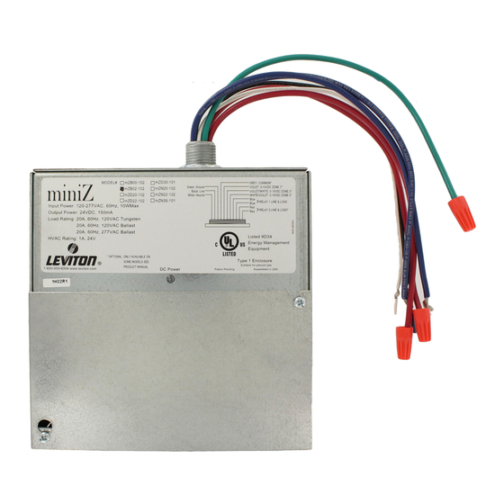
This user's guide applies to the following part numbers:
Model
Number
mZ b0 2-10 2
mZ d2 2-10 2
mZ n2 2-10 2
mZb0 2-C0 2
mZd2 2-C0 2
mZn2 2-C0 2
Features between models vary. As such, not all information in this manual
1.800.561.8187
Daylight Harvesting Made Simple.
Description
Basic Version, Two Room, 2 Relay, 120V or 277V
Dimming Version, Two Room, 2 Relay, 120V or 277V
Dimming Version, Dual Room, 2 Relay, 120V or 277V
Basic Version, Two Room, 2 Relay, 347V
Dimming Version, Two Room, 2 Relay, 347V
Dimming Version, Two Room, 2 Relay, 347V
applies to all models.
www.
0-10V
Outputs
0
2
2
0
2
2
information@itm.com
.com
Relay
Outputs
2
2
2
2
2
2
Advertisement

Related Manuals for Leviton miniZ Series


Summary of Contents for Leviton miniZ Series
- Page 1 Daylight Harvesting Made Simple. This user’s guide applies to the following part numbers: Model 0-10V Relay Description Outputs Outputs Number mZ b0 2-10 2 Basic Version, Two Room, 2 Relay, 120V or 277V mZ d2 2-10 2 Dimming Version, Two Room, 2 Relay, 120V or 277V mZ n2 2-10 2 Dimming Version, Dual Room, 2 Relay, 120V or 277V mZb0 2-C0 2...
- Page 2 TABLE OF CONTENTS …………………………………………..…….. 2 HYSICAL NSTALLATION ………………………………………..………. 4 ONNECT OLTAGE ……………………………………………..…. 6 ONNECT OLTAGE ……………………………………………..…. 8 ONNECT OLTAGE DIP S – B ………………. 10 ONFIGURATION WITCH ETTINGS LOCK DIP S – B ….…………… 12 ONFIGURATION WITCH ETTINGS LOCK DIP S –...
- Page 3 STEP 1 PHYSICAL INSTALLATION OUNTING EATURES The Power Pack is suitable for plenum use, indoor only, 0 - 40°C, 5 - 95% humidity without condensation. The supply circuit and load circuits of the miniZ Power Pack are pre-wired to the control board. Color coded lead wires are provided for quick connections in a junction box.
- Page 4 PHYSICAL INSTALLATION High Voltage Compartment This area cannot be accessed in the field. Nipple Lead wires exit the compartment through The fitting on the top of the miniZ Power Pack the top of the enclosure. There are leads attaches directly to a junction box or enclosure. supplied for field connections to circuits Two 0.2"...
- Page 5 STEP 2 CONNECT LINE VOLTAGE Relay 1 Line/Load Ratings: 20A at 120VAC Tungsten/Ballast 20A at 277VAC Ballast 15A at 347VAC (347V Models Only) Normally Open, Electrically held. Color Code: Blue – Line, 12 AWG Blue – Load, 12 AWG Control Power Circuit Voltage Rating: 120 –...
- Page 6 CONNECT LINE VOLTAGE Relay 2 Line/Load Ratings: 20A at 120VAC Tungsten/Ballast 20A at 277VAC Ballast 15A at 347VAC (347VModels Only) Normally Open, Electrically held. Color Code: Red – Line, 12 AWG Red – Load, 12 AWG Zone Common Color Code: Gray – 22 AWG Not available on Basic Model Zone 1 Analog Output 0 –...
- Page 7 STEP 3 CONNECT LOW VOLTAGE Load Shed Input Occupancy Sensor Disabled / Emergency Input Label: S Label: OCC D ISABLE MERGENCY This signal would originate from an energy Set by DIP Switch: Block 1 Number 1 management system and is a +24V input signal. When the input goes high (+24V) the Power Pack This is a +24V input signal.
- Page 8 CONNECT LOW VOLTAGE STEP 6 Photocell Input 1 Photocell Input 2 Label: P Label: P HOTO HOTO This set of terminal blocks is dedicated to the This set of terminal blocks is dedicated to the connection of Photocell number 1. The Photocell connection of Photocell number 2.
- Page 9 STEP 4 CONNECT LOW VOLTAGE Emergency / HVAC Label: R N/O, R HVAC A jumper between pins 1 and 2 will result in There is one Low Voltage relay output rated HVAC functionality. In this mode the relay will for 1A @ 24V which can be switched between change state when either room is occupied.
- Page 10 CONNECT LOW VOLTAGE STEP 6 Low Voltage Switch Inputs Label: S 1; O , +24V, P WITCH ILOT 2; O , +24V, P WITCH ILOT There are two low voltage switch inputs. Switch 1 provides control for Room 1 and Room 2 provides control for Room 2.
- Page 11 CONFIGURATION DIP SWITCH SETTINGS – BLOCK ONE STEP 5 Emergency / Occupancy Sensor Disable DIP Switch: Block 1 Switch 1 Label: E MERG ISABLE This configures the response to a signal (+24V) at the OCC Disable/Emergency input terminal. If the switch is in the off position (EMERG), the response to a connection to common will be to turn all relays on and raise all 0 –...
- Page 12 CONFIGURATION DIP SWITCH SETTINGS – BLOCK ONE STEP 6 Photocell Slow Response / Fast Response DIP Switch: Block 1 Switch 6 Label: PC S / PC F This setting determines the speed at which the system will respond to changes in light levels detected by the Photocell.
- Page 13 STEP 6 CONFIGURATION DIP SWITCH SETTINGS – BLOCK TWO 2 - DIP S LOCK WITCHES WITCHES SHOWN IN THE POSITION Off + Off = OFF Off + On = .5 Hr On + On = 2 Hr WITCH NPUT YPES Set by DIP Switches: Block 2 Number 3 and/or Number 6 Settings: ON = Analog, OFF = Switched There are several modes of switch inputs;...
- Page 14 CONFIGURATION DIP SWITCH SETTINGS – BLOCK TWO STEP 6 One Button Maintained Mode (Toggle Switch) Set by DIP Switch: Block 2 Number 1 and/or Number 4 = Off Block 2 Number 2 and/or Number 5 = On Block 2 Number 3 and/or Number 6 = Off Connections: In this mode, the On input is used to both turn on and turn off the zone.
- Page 15 STEP 6 CONFIGURATION DIP SWITCH SETTINGS – BLOCK TWO Special Function Leviton Switches (LV200, LV220, LV221, and LV240) Set by DIP Switch: Block 2 Number 1 & 2 or Number 4 & Settings: ON Connections: In this mode the switches should be wired so that the ON, OFF, PILOT, +24V, and COM wires are connected.
- Page 16 CONFIGURATION DIP SWITCH SETTINGS – BLOCK THREE STEP 7 DIP Switch Block 3 Photocell Maximum Foot Candle DIP Switch HOTOCELL Set by DIP Switch: Block 3 Number 1 to 8 Application – Open Loop Daylight Harvesting ONLY This 8 position DIP switch is used to set the maximum foot candle value of the photocell being used with the system.
- Page 17 STEP 8 CONFIGURATION TRIM POT SETTINGS AXIMUM INIMUM Adjust this trim pot to set the minimum level the Adjust this trim pot to set the upper limit for the 0 0 – 10VDC outputs will dim during daylight – 10VDC Ballast outputs. The full range of the harvesting mode operation.
- Page 18 CONFIGURATION TRIM POT SETTINGS STEP 6 LLF T SHED HOTOCELL Adjust this trim pot to determine the action taken Dimmed Model, Closed Loop when the L ) input is active. SHED Used to input a LLF for both rooms. The LLF is 20% when the trim pot is set at 0 and 0% when the Application trim pot is at 10.
- Page 19 STEP 9 NOTES: DAYLIGHTING CONFIGURATION Setup To setup your device in either open loop or closed loop mode, please reference Step 4, Settings, found on page 3 of this document. This section details with specific calibration and configuration of your miniZ device when in each of these modes. Open-Loop Operation Typical open-loop systems employ a photocell positioned towards the daylight source (window, skylight, etc).
- Page 20 NOTES: BURN IN & AUTO CAL FEATURES STEP 10 ALIBRATION IN F EATURE LOSED PERATION Set by DIP Switch: Block 1 Number 7 On Set by DIP Switch: Block 1 Number 5 On The Burn IN feature of the miniZ Power Pack provides an automatic initializing cycle for new The Auto Calibration feature of the miniZ Power fluorescent lamps.
- Page 21 Leviton warrants to the original consumer purchaser and not for the benefit of anyone else that this product at the time of its sale by Leviton is free of defects in materials and workmanship under normal and proper use for five years from the purchase date. Leviton’s only obligation is to correct such defects by repair or replacement, at its option, if within such five year period the product is returned prepaid, with proof of purchase date, and a description of the problem.This warranty excludes and there is disclaimed...
- Page 22 WITCH UNCTION EFAULT OSITION IN ALL MODELS MERG ISABLE MERG PARE OCAL NABLE OCAL OCAL OCAL PC S / PC F PC F LOSED LOSED EFAULT OSITIONS WITCH DIMMING & UNCTION BASIC NETWORK MODELS MODELS S1 – 1 B / 2 B ETUP FOR OPERATION S1 –...
- Page 23 TRIM POTS BASIC M DIMMING & NETWORK M ODEL ODELS LABEL UNCTION EFAULT ETTING UNCTION EFAULT ETTING Max output of 0 - 10V Outputs, 10 (100%) Range 6 - 10V. Minimum daylighting level, Range 0 - 4V. Left – Relay 1 sheds Center –...
Need help?
Do you have a question about the miniZ Series and is the answer not in the manual?
Questions and answers