Table of Contents
Advertisement
Quick Links
Instructions
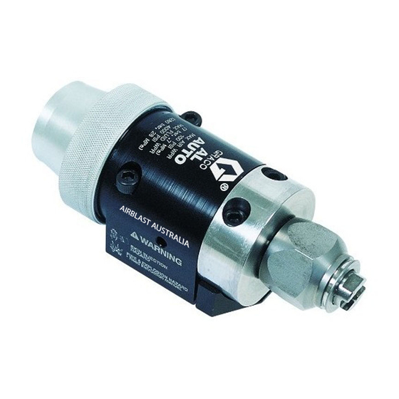
Automatic Airless
Spray Guns
Part 26C624
For use with spraying high-pressure protective coating materials.
5000 psi (35 MPa, 345 bar) Maximum Working Fluid Pressure
Part 288048
For airless spraying of paints and coatings.
5000 psi (35 MPa, 345 bar) Maximum Working Fluid Pressure
Part 288554
For sealant streaming applications.
5000 psi (35 MPa, 345 bar) Maximum Working Fluid Pressure
Part 26C625
For use with spraying high-pressure protective coating materials.
7250 psi (50 MPa, 499 bar) Maximum working Pressure
Mounting manifolds must be ordered separately. Refer to Parts section.
Important Safety Instructions
Read all warnings and instructions in this
manual before using the equipment.
Save these instructions.
Important Medical Information
Read the medical alert card provided with
the gun. It contains injection injury
treatment information for a doctor. Keep it
with you when operating the equipment.
311053L
Model 26C624
Models 288048 and 288554
Model 26C265
II 2 G Ex h IIB T6 Gb
EN
Advertisement
Table of Contents
Troubleshooting

Related Manuals for Graco 26C624


Summary of Contents for Graco 26C624
- Page 1 Instructions Automatic Airless 311053L Spray Guns Part 26C624 For use with spraying high-pressure protective coating materials. 5000 psi (35 MPa, 345 bar) Maximum Working Fluid Pressure Part 288048 For airless spraying of paints and coatings. 5000 psi (35 MPa, 345 bar) Maximum Working Fluid Pressure Part 288554 For sealant streaming applications.
-
Page 2: Table Of Contents
Daily Gun Care ......13 26C624 ....... 35 General System Maintenance . -
Page 3: Warnings
Warnings Warnings The following warnings are for the setup, use, grounding, maintenance, and repair of this equipment. The exclamation point symbol alerts you to a general warning and the hazard symbols refer to procedure-specific risks. When these symbols appear in the body of this manual or on warning labels, refer back to these Warnings. Product-specific hazard symbols and warnings not covered in this section may appear throughout the body of this manual where applicable. - Page 4 Warnings WARNING FIRE AND EXPLOSION HAZARD Flammable fumes, such as solvent and paint fumes, in work area can ignite or explode. Paint or solvent flowing through the equipment can cause static sparking. To help prevent fire and explosion: • Use equipment only in well-ventilated area. •...
-
Page 5: Installation
Installation Installation Ventilate Spray Booth Non-circulating System: 1. Apply anti-seize lubricant 222955 to the threads and mating faces of manifold (102), plug (109), and elbow (107), supplied unassembled. 2. Install an elbow (107) in one fluid port of the NOTE: Check and follow all National, State, and Local manifold (102), and a plug (109) in the other port. -
Page 6: Install Air Fittings
Installation Install Air Fittings Ground Pump Ground the pump by connecting a ground wire and 1. Install 1/4 in. tube fitting into the cylinder (CYL) air clamp between the fluid supply and a true earth ground port. as instructed in your separate pump instruction manual. 2. -
Page 7: Mount Gun
Installation Mount Gun Stationary Support Mount All Manifolds Reciprocating Arm Rod Mount To mount the gun on a stationary support (refer to F . 4. Manifolds 241161, 241162, and 26C622 and Mounting Hole Layout, page 37): To mount the gun on a reciprocating arm rod [0.5 in. (13 1. -
Page 8: Setup
Setup Setup Air Line and Accessory Fluid Line and Accessory Recommendations Recommendations 1. Install an air pressure regulator on the gun cylinder air supply line. A minimum of 70 psi (0.49 MPa, 4.9 bar) air pressure must be supplied to the cylinder for proper operation. - Page 9 Setup Manifolds 288219, 288220, and 26C622 Manifold 244930 6. In a circulating system, connect an electrically 7. This manifold is equipped with passages for conductive fluid hose to the gun fluid outlet (G). circulating water to maintain the temperature of the gun.
-
Page 10: Flush Spray Gun
Setup Flush Spray Gun RAC Tip 1. Perform Pressure Relief Procedure; see page 12. Before running any paint through the spray gun: 2. Snap gasket (9b) on fluid seal (9a). Use tool (A) to 1. Flush the gun with a solvent that is compatible with insert gasket and seal into housing (insert the the fluid to be sprayed, using the lowest possible seal-end in first). -
Page 11: Adjust Spray Pattern
Setup Adjust Spray Pattern Adjust a Streaming Tip Select a tip that will supply a stream at the required flow rate at the lowest pressure. Equipment surfaces and fluid that is heated can become very hot during operation. To avoid severe burns, wear gloves if the fluid temperature exceeds 110 °F (43 °C). -
Page 12: Operation
Operation Operation fully relieved after following the steps above, very Pressure Relief Procedure slowly loosen the hose end coupling and relieve pressure gradually, then loosen the coupling Follow the Pressure Relief Procedure completely. Now clear the tip or hose obstruction. whenever you see this symbol. -
Page 13: Daily Gun Care
Daily Gun Care Daily Gun Care NOTICE Methylene chloride with formic or propionic acid is not recommended as a flushing or cleaning solvent with this gun as it will damage aluminum and nylon components. NOTICE Solvent left in gun air passages could result in a poor quality paint finish. -
Page 14: General System Maintenance
Daily Gun Care General System Maintenance Clean Spray Tips and Clear Clogs • Perform Pressure Relief Procedure, page 12. • Clean the fluid and air line filters daily. RAC Tips • Check for any fluid leakage from the gun and fluid 1. -
Page 15: Daily Flushing Procedure
Daily Gun Care 2. Remove the spray tip. Clean the parts. Daily Flushing Procedure 3. Supply a compatible solvent to the gun fluid inlet. 4. Start the pump and operate it at its lowest pressure. 5. Trigger the gun into a grounded metal waste To avoid fire and explosion, always ground the entire container until all the material is removed from the system, including the gun and waste container. -
Page 16: Troubleshooting
Troubleshooting Troubleshooting NOTE: Check all possible remedies in the NOTE: Some improper patterns are caused by the troubleshooting charts before disassembling the gun. improper balance between air and fluid. Refer to Spray Pattern Troubleshooting, page 18. General Troubleshooting Problem Cause Solution Fluid leakage through venting Worn o-rings or packings on needle... - Page 17 Troubleshooting Problem Cause Solution Fluid needle will not trigger Loose or missing fluid needle stop Replace stop (17) or tighten setscrew (17) or setscrew (16). (16). Broken fluid needle (12). Replace fluid needle (12). Air leaking around piston (21). Replace o-ring (22) or piston assembly (21).
-
Page 18: Spray Pattern Troubleshooting
Troubleshooting Spray Pattern Troubleshooting Problem Cause Solution Fluttering spray. Insufficient fluid supply. Adjust fluid regulator or fill fluid supply tank. Air in paint supply line. Check, tighten siphon hose connections, bleed air from paint line. Spitting spray. Worn seat (10, 41) or needle (12) Inspect seat and needle for wear. -
Page 19: Service
(8). See F . 16, page 20. 12. Remove the large o-ring (22) from the piston and Models 26C624 and 26C625: Unscrew the XHD the smaller o-ring (23) from the piston shaft. RAC Tip Guard (7). Remove the two o-rings (25, 26) from each of the piston stems. - Page 20 Service 11† TI8117a 3† SERVICE NOTES: Models 288048 and 26C625 shown Seat gasket (11) must be replaced if seat (10) is removed or replaced to avoid fluid leakage Lubricate threads with anti-seize lubricant Lubricate with light-weight oil Do not lubricate Torque to 20-25 ft-lb (27-34 N•m) Apply semi-permanent anaerobic sealant Torque to 6.5-7.5 in-lb (0.73-0.85 N•m)
-
Page 21: Reassembly
(9) and gasket (8) in the tip retainer nut (7). the matching holes in the housing. Models 26C624 and 26C625: Make sure gasket NOTICE (9b) is snapped onto fluid seal (9a) and is properly Install a new gasket (11) whenever you remove the inserted into the housing. -
Page 22: Parts
Parts Parts Model 26C624 6† 5† 11† 12 (ref) SERVICE NOTES: Seat gasket (11) must be replaced if seat (10) is removed or replaced to avoid fluid leakage Lubricate threads with anti-seize lubricant Lubricate with light-weight oil Do not lubricate Torque to 20 - 25 ft-lb (27-34 N•m) - Page 23 Parts Parts List - 26C624 Ref. Part Description Qty. Ref. Part Description Qty. 19 114138 SPRING, compression - - - - - BODY 20 114139 SPRING, compression - - - - - HOUSING, fluid 240895 PISTON, assy 3† 288200 GASKET, fluid, acetal...
-
Page 24: Model 26C625
Parts Model 26C625 † SERVICE NOTES: Seat gasket (11) must be replaced if seat (10) is removed or replaced to avoid fluid leakage Lubricate threads with anti-seize lubricant Lubricate with light-weight oil Do not lubricate Torque to 20 - 25 ft-lb (27 - 34 N•m) Apply semi-permanent anaerobic sealant Torque to 2 - 4 in-lb (0.23 - 0.45 N•m) Tighten cap (18) until it bottoms out... - Page 25 Parts Parts List - 26C625 Ref. Part Description Qty. Ref. Part Description Qty. 19 18C161 SPRING, compression - - - - - BODY 20 114139 SPRING, compression - - - - - HOUSING, fluid 578002 PISTON, assy 3† 826267 GASKET, fluid, (pack of 10) 115066 PACKING, o-ring, 192687...
-
Page 26: Model 288048
Parts Model 288048 5† 11† 6† 3† 12 (ref) TI8090a SERVICE NOTES: Seat gasket (11) must be replaced if seat (10) is removed or replaced to avoid fluid leakage Lubricate threads with anti-seize lubricant Lubricate with light-weight oil Do not lubricate Torque to 20-25 ft-lb (27-34 N•m) Apply semi-permanent anaerobic sealant Torque to 6.5-7.5 in-lb (0.73-0.85 N•m) -
Page 27: Model 288554
Parts Model 288554 11† 3† Ref. only Ref. only 12 (ref) TI9523a SERVICE NOTES: Seat gasket (11) must be replaced if seat (41) is removed or replaced to avoid fluid leakage Lubricate threads with anti-seize lubricant Lubricate with light-weight oil Do not lubricate Torque to 20-25 ft-lb (27-34 N•m) Apply semi-permanent anaerobic sealant... - Page 28 Parts Parts List - 288048 and 288554 Ref. Part Description Qty. Ref. Part Description Qty. 19 SPRING, compression - - - - - BODY 114138 - - - - - HOUSING, fluid 120696 3† 288200 GASKET, fluid, acetal homopolymer, pack of 10 20...
- Page 29 Parts Part 241161 Part 26C622 North America Manifold (NPT fittings) Used on 26C625 Part 241162 Ref. Part Description Qty. International Manifold (JIC fittings) 301 18A468 MANIFOLD, air 302 18A933 MANIFOLD, fluid Ref. Part Description Qty. 303 120388 FITTING, tube, air linet; 1/4 in. 101 192441 MANIFOLD, air OD tube x 1/8 npt(m)
-
Page 30: Gg0 Series Tip Selection Charts
GG0 Series Tip Selection Charts GG0 Series Tip Selection Charts GG0 Series Spray Tips Maximum Pattern Width at 12 in. (300 mm) * Fluid Output oz/min (lpm) 10 to Orifice Size in. at 600 psi 2 to 2.5 4 to 4.5 6 to 6.5 8 to 8.5 10.5... -
Page 31: Xhd Rac Switch Tip Selection Charts
XHD RAC Switch Tip Selection Charts XHD RAC Switch Tip Selection Charts XHD RAC Switch Tips ORIFICE SIZE - INCHES (mm) 0.007 0.009 0.011 0.013 0.015 0.017 0.019 0.021 0.023 0.025 0.027 0.029 0.031 0.033 0.035 0.037 0.039 (51-102) (102-152) (152-203) 8-10 (203-254) -
Page 32: Sealer Application Tip And Air Cap Selection Charts
Sealer Application Tip and Air Cap Selection Charts Sealer Application Tip and Air Cap Selection Charts Shower Tip Number of Orifice Size in. (mm) Orifices Part C08224 0.021 (0.533) Streaming Tips Orifice Size Orifice Size in. (mm) in. (mm) Part Part 0.039 (0.991) 270037... -
Page 33: Accessories
Accessories Accessories Filter Kit Consists of just the filter element Filter 60 mesh, qty. 25 - 238564 Filter 60 mesh, qty. 3 - 238563 Gun Manifolds Filter 100 mesh, qty. 25 - 238562 Order separately; not included with gun. Filter 100 mesh, qty. 3 - 238561 (See Parts List - 288048 and 288554, page 28.) Part No. -
Page 34: Dimensions
Dimensions Dimensions 288048, 288554 2.0 in. (5.1 cm) 3.86 in. (9.8 cm) 5.23 in. (13.9 cm) 3.0 in. (7.6 cm) 1.375 in. (3.5 cm) 2.0 in. (51 cm) 2.245 in. (5.7 cm) 0.5 in. (1.3 cm) . 20 311053L... -
Page 35: 26C624
Dimensions 26C624 2.52 in. (6.4 cm) 2.0 in. (5.1 cm) 3.86 in. (9.8 cm) 6.51 in. (16.5 cm) 604 in. (1.5 cm) 3.24 in. (8.2 cm) 1.375 in. (3.5 cm) 3.0 in. (7.6 cm) 2.0 in. (5.1 cm) 0.5 in. -
Page 36: 26C625
Dimensions 26C625 2.52 in. (6.4 cm) 2.0 in. (5.0 cm) 3.86 in. (9.8 cm) 6.51 in. (16.5 cm) 604 in. (1.5 cm) 3.24 in. (8.2 cm) 1.375 in. (3.4 cm) 3.0 in. (7.6 cm) 2.0 in. (5.1 cm) 0.5 in. 2.83 in. -
Page 37: Mounting Hole Layout
Mounting Hole Layout Mounting Hole Layout 0.5 in. (1.3 cm) TI8116a 0.4 in. 0.805 in. (2.1 cm) Two M5 x 0.8 x 0.25 in. (10.1 mm) (6.3 mm) holes 1.750 in. 0.187 in. (4.8 mm) (4.5 cm) 1.375 in. (3.5 cm) Remove set screws when using bottom Two 0.128 diameter x... -
Page 38: End Of Product Life
End of Product Life End of Product Life At the end of a product’s useful life, recycle it in a responsible manner. California Proposition 65 CALIFORNIA RESIDENTS WARNING: Cancer and reproductive harm – www.P65warnings.ca.gov. 311053L... -
Page 39: Technical Data
1.17 lb 529 g Wetted Parts Stainless Steel, Carbide, Ultra High Molecular Weight Polyethylene, Acetal, PEEK, Chemically Resistant Fluoroelastomer, PTFE Spray Gun 26C624 Maximum working fluid pressure 5000 psi 36 MPa, 360 bar Minimum air cylinder actuation pressure at 4000 psi 70 psi 0.49 MPa, 4.9 bar... -
Page 40: Graco Standard Warranty
With the exception of any special, extended, or limited warranty published by Graco, Graco will, for a period of twelve months from the date of sale, repair or replace any part of the equipment determined by Graco to be defective.
Need help?
Do you have a question about the 26C624 and is the answer not in the manual?
Questions and answers